Mass Conservation and Flow Rate Measurements
Overview
Source: Ricardo Mejia-Alvarez and Hussam Hikmat Jabbar, Department of Mechanical Engineering, Michigan State University, East Lansing, MI
The purpose of this experiment is to demonstrate the calibration of a flow passage as a flowmeter using a control volume (CV) formulation [1, 2]. The CV analysis focuses on the macroscopic effect of flow on engineering systems, rather than the detailed description that could be achieved with a detailed differential analysis. These two techniques should be considered complementary approaches, as the CV analysis will give the engineer an initial basis on which route to pursue when designing a flow system. Broadly speaking, a CV analysis will give the engineer an idea of the dominant mass exchange in a system, and should ideally be the initial step to take before pursuing any detailed design or analysis via differential formulation.
The main principle behind the CV formulation for mass conservation is to replace the details of a flow system by a simplified volume enclosed in what is known as the control surface (CS). This concept is imaginary and can be defined freely to cleverly simplify the analysis. For instance, the CS should 'cut' inlet and outlet ports in a direction perpendicular to the dominant velocity. Then, the analysis would consist of finding the balance between the net mass flux through the CS and the rate of change of mass inside the CV. This technique will be demonstrated with the calibration of a smooth contraction as a flowmeter.
Procedure
1. Setting the facility
- Make sure that there is no flow in the facility.
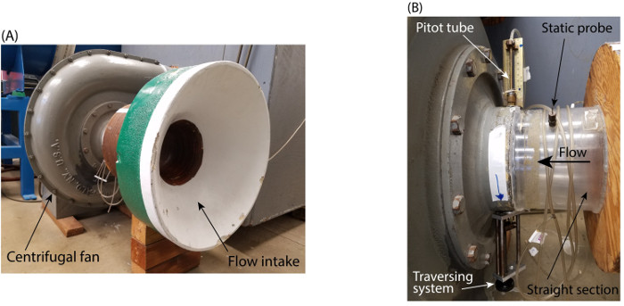
- Verify that the data acquisition system follows the schematic in Figure 1B.
- Connect the positive port of pressure transducer #1 (see Figure 1B for reference) to the traversing Pitot tube (
 ).
). - Connect the negative port of this same pressure transducer to the static probe of the intake passage (
Results
For a given restriction of the flow at the fan's discharge, Figure 3A shows the measurements of dynamic pressure ( ) at different radial locations inside the pipe after traversing with the Pitot tube. These values were used to determine the local velocity at those radial locations, and the results are shown in Figure 3B. After using the trapezoidal rule on these data to solve
Application and Summary
We demonstrated the application of control volume analysis of conservation of mass to calibrate a flow passage as a flow meter. To this end, we demonstrated the use of a Pitot-static system to determine the flow rate across the flow passage using integration over the velocity profile. Then, the concept of discharge coefficient was incorporated to account for the effect of boundary layer growth near the walls of the flow passage. Based on a set of velocity measurements for different flow rates, we developed a regression t
References
- White, F. M. Fluid Mechanics, 7th ed., McGraw-Hill, 2009.
- Munson, B.R., D.F. Young, T.H. Okiishi. Fundamentals of Fluid Mechanics. 5th ed., Wiley, 2006.
- Chapra, S.C. and R.P. Canale. Numerical methods for engineers. Vol. 2. New York: McGraw-Hill, 1998.
- Buckingham, E. Note on contraction coefficients of jets of gas. Journal of Research, 6:765-775, 1931.
- Lienhard V, J.H. and J.H. Lienhard IV. Velocity coefficients for free jets from sharp-edged orifices. ASME Journal of Fluids Engineering, 106:13-17, 1984.
Skip to...
Videos from this collection:

Now Playing
Mass Conservation and Flow Rate Measurements
Mechanical Engineering
22.6K Views

Buoyancy and Drag on Immersed Bodies
Mechanical Engineering
30.0K Views

Stability of Floating Vessels
Mechanical Engineering
22.6K Views

Propulsion and Thrust
Mechanical Engineering
21.7K Views

Piping Networks and Pressure Losses
Mechanical Engineering
58.1K Views

Quenching and Boiling
Mechanical Engineering
7.7K Views

Hydraulic Jumps
Mechanical Engineering
41.0K Views

Heat Exchanger Analysis
Mechanical Engineering
28.0K Views

Introduction to Refrigeration
Mechanical Engineering
24.7K Views

Hot Wire Anemometry
Mechanical Engineering
15.6K Views

Measuring Turbulent Flows
Mechanical Engineering
13.5K Views

Visualization of Flow Past a Bluff Body
Mechanical Engineering
11.9K Views

Jet Impinging on an Inclined Plate
Mechanical Engineering
10.7K Views

Conservation of Energy Approach to System Analysis
Mechanical Engineering
7.4K Views

Determination of Impingement Forces on a Flat Plate with the Control Volume Method
Mechanical Engineering
26.0K Views
Copyright © 2025 MyJoVE Corporation. All rights reserved
 ). Hence, the reading of this pressure transducer will be directly (
 ). Enter this value in Table 1.
 ). Hence, the reading of this transducer will be directly (
 ).
). ). Enter this value in Table 1.
 mm (here,
 mm).
mm).

 , as the abscissas (Figure 3).
 as the abscissas.