Sign In

Aerodynamic Performance of a Model Aircraft: The DC-6B

Overview

Source: Jose Roberto Moreto and Xiaofeng Liu, Department of Aerospace Engineering, San Diego State University, San Diego, CA

The low-speed wind tunnel is a valuable tool to study aircraft aerodynamic characteristics and evaluate aircraft performance and stability. Using a scale model of a DC-6B aircraft that has a removable tail and a 6-component external aerodynamic force balance, we can measure the lift coefficient (CL), drag coefficient (CD), pitching moment coefficient (CM), and yaw moment coefficient (CN) of the model airplane with and without its tail and evaluate the effect of the tail on aerodynamic efficiency, longitudinal stability and directional stability.

In this demonstration, airplane aerodynamic characteristics and flight performance and stability are analyzed using the aerodynamic force balance measurement method. This method is widely used in aerospace industries and research labs for aircraft and rocket development. Here, a model DC-6B airplane is analyzed at different flow conditions and configurations, and its behavior is analyzed when it is subjected to sudden changes.

Principles

To evaluate aerodynamic characteristics, it is important to determine how the aerodynamic coefficients change with respect to the airplane attitude, i.e., the angle of attack, yaw angle and roll angle, for a given flight condition. The aerodynamic force balance is a widely used method to directly measure the forces and moments experienced by a model. From the measured forces and moments, as well as the airflow temperature, static pressure and total pressure, the aerodynamic coefficients can be obtained for several angles of attack and yaw angles.

It is possible to obtain the aerodynamic characteristics of a full-scale object by testing a small-scale model, provided that the dynamic similarity condition is met and the appropriate corrections are applied. In the case of an incompressible steady flow, the relevant similarity parameter is the Reynolds number based on a proper reference length.

For a low speed airplane, like the DC-6B, the aerodynamic characteristics can be measured in a small, low-speed wind tunnel since it is possible to match the Reynolds number for the same flight conditions. Under these conditions, one can obtain the dependence of drag and lift on the angle of attack, α. This dependence on alpha can be used to evaluate the airplane performance.

Once the aerodynamic coefficients are measured for several conditions and configurations, for example using two different tail geometries, the stability derivatives (dCM/, dCN/), lift slope (dCL/), maximum lift coefficient, maximum lift-to-drag ratio, and other aerodynamic characteristics can be found. From these aerodynamic coefficients, the effect of modification or design choices on the airplane stability and performance can be determined.

The stability derivatives indicate whether the aircraft is stable or unstable. For example, if the angle of attack of the aircraft suddenly increases due to a gust of wind, the response of the aircraft characterizes its stability. If the angle of attack continues increasing indefinitely, the aircraft is said to be unstable. However, if the angle of attack returns to its initial value, the attitude before the gust, the aircraft is said to be stable. The same is true for the directional stability; if the tendency of the aircraft is to return to its initial yaw angle after a sudden change, the aircraft is said to be directionally stable.

In this demonstration, the aerodynamic force balance for force and moment measurements in a wind tunnel, will be introduced. To remove the contributions of the supporting struts and the model's weight, the balance will be tared to ensure the final results on aerodynamic force and moments are due to the aircraft only. Additionally, this demonstration illustrates the effect of a tail in a conventional airplane design and its importance in longitudinal and lateral aircraft stability.

Procedure

The DC-6B model set-up on the aerodynamic force balance is displayed below.


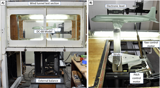
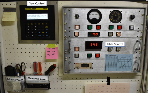
Figure 1. Mounted DC-6B model. A) DC-6B model inside low-speed wind tunnel test section with an external aerodynamic balance. B) DC-6B Model mounted on the balance by three articulated points. There is also a yaw angle control motor, pitch control motor and an electronic level to calibrate the pitch angle.


Figure 2. Low speed wind tunnel control panel. The pitch angle and the yaw angle can be electronically controlled from the panel during the tests with the wind tunnel running.

1. Calibration of set-up

  1. Lock the external balance on the wind tunnel control panel.
  2. Install the struts on the aerodynamic balance as illustrated in Figure 1. The struts are bolted to the balance.
  3. Set the yaw angle to zero by adjusting the knob on the yaw motor, and set the pitch angle to zero using the pitch motor. The pitch angle should be calibrated using an electronic level. The measurements are first made at different angles with only the struts in place, and no model airplane. This enables the effects of the struts from the airplane to be subtracted.
  4. Turn on the computer and external balance force acquisition system. It is necessary to turn on the system at least 30 min prior testing.
  5. Open the measurement control software.
  6. Record the room pressure and temperature. Make sure to correct the barometric pressure using the local temperature and local gravity.
  7. Check if the test section and wind tunnel are free from debris and loosen parts, then close the test section doors.
  8. Unlock the external balance and set the wind tunnel speed to zero.
  9. Turn on the wind tunnel and wind tunnel cooling system.
  10. Record the balance forces and moments.
  11. Set the dynamic pressure to 7 inches H2O, and record the balance forces and moments.
  12. Use the yaw control to set the yaw angle to 5°. Adjust the dynamic pressure to 7 inches H2O if necessary.
  13. Record the balance forces and moments. Change yaw angle to 10°. Adjust the dynamic pressure to 7 inches H2O if necessary.
  14. Record the balance forces and moments.
  15. Turn off the wind tunnel and lock the external balance.
  16. Install the DC-6B model with the tail on.
  17. Calibrate the angle of attack and pitch indicator. Calibrate the pitch angle prior to the test using an electronic level.
  18. Unlock the external balance.
  19. Set the angle of attack by pressing the nose up or down on the control panel Figure 2. Angles of attack for testing α = -6°, -4°, -2°, 0°, 2°, 4°, 6°, 8°, 10°.
  20. Record the balance forces and moments.
  21. Repeat steps 1.19 to 1.20, incrementally increasing the angle of attack until all the test points are complete.
  22. Return the angle of attack, α, to zero and set yaw angle. Yaw angles for testing β = 0°, 5°, 10°.
  23. Record the balance forces and moments.
  24. Repeat steps 1.22 to 1.23 incrementally increasing the yaw angle until all the test points are complete.
  25. Lock the external balance and remove the tail from the DC-6B model. Install the tail cone, and repeat steps 1.19 to 1.24.
  26. When all data has been collected, turn off the wind tunnel cooling system, lock the external balance, and turn off the wind tunnel.

2. Testing at non-zero wind speeds

  1. Check if the test section and wind tunnel are free from debris and loosen parts and then close the test section doors.
  2. Set pitch angle to zero.
  3. Unlock the external balance.
  4. Set the wind tunnel speed dial to zero and turn on the wind tunnel and wind cooling system.
  5. Record the balance forces and moments.
  6. Set dynamic pressure to 7 inches H2O.
  7. Set angle of attack, starting with α = -6°. Angles of attack for testing α = -6°, -4°, -2°, 0°, 2°, 4°, 6°, 8°, 10°.
  8. Adjust dynamic pressure to 7 inches H2O if necessary, and record the balance forces and moments.
  9. Repeat steps 2.7 - 2.8 incrementally increasing the angle of attack until all the test points are executed.
  10. Return the angle of attack to zero and set the yaw angle. The following yaw angles should be tested β = 0°, 5°, 10°.
  11. Adjust dynamic pressure to 7 inches H2O if necessary, and record the balance forces and moments.
  12. Repeat steps 2.10 - 2.11 incrementally increasing the yaw angle until all test points are executed.
  13. Slowly decrease the airspeed to zero, then lock the external balance.
  14. Remove the DC-6B model tail cone and install the complete tail.
  15. Repeat steps 2.7 to 2.12.
  16. When all data has been collected, turn off the wind tunnel cooling system, lock the external balance, and turn off the wind tunnel.
Results

In this demonstration, the performance and stability characteristics of a DC-6B model in two configurations were measured. In one configuration, a conventional airplane tail was attached to the model (tail-on), and in the second configuration, the tail was removed and replaced with a cone (tail-off). For each configuration, the variation of lift coefficient and drag coefficient with angle of attack was determined (Figure 3). The variation in pitch moment coefficient and yaw moment coefficient with respect to angle of attack and beta was also investigated (Figure 4).

The results show the aerodynamic effects of the tail. In Figure 3, although the tail increases the maximum lift and the drag, overall the tail decreases the aerodynamic performance. When the tail is off, the model is longitudinally and directionally unstable (Figure 4). Therefore, the airplane tail is necessary to achieve stability, even though it could result in reduced aircraft performance.


Figure 3. Performance evaluation curves for tail-on and tail-off configurations. A) Lift coefficient vs α; B) Drag coefficient vs α; C) Drag polar; and D) L/D vs α. Please click here to view a larger version of this figure.


Figure 4. Performance evaluation curves for tail on and tail off configurations. A) Pitch moment coefficient vs α; B) Yaw moment coefficient vs β. Please click here to view a larger version of this figure.

Application and Summary

Testing a small-scale model using an aerodynamic balance in a wind tunnel enables the determination of major aerodynamic characteristics of an aircraft. A 6-component balance measures three force components, lift, drag, and lateral forces, and three moment components, pitch, yaw, and roll moments.

When the dynamic similarity between the full-scale object and the model is achieved, for example the Reynolds number is the same for the case of incompressible steady flow, then the aerodynamic coefficients obtained using the small-scale model are applicable to the full-scale object and aerodynamic characteristics, such as performance and static stability, can be determined.

Force and moments measurements by an external balance in a wind tunnel have several applications. This method is widely used in the aerospace industry; however, it has been applied successfully in research and development in many areas, for example in naval engineering, automotive industries, and civil engineering.

There are several applications in naval engineering. For example, sail boats and race boats are significantly affected by aerodynamic forces, and their effect on the vessel needs to be considered to optimize performance. For low-speed ship design, aerodynamic forces should be considered to reduce fuel consumption and improve overall performance.

Another industry that benefits from wind tunnel testing is the automotive industry. Wind tunnel testing is used to determine the drag forces, lateral forces and moments experienced by a car. This is now a standard practice for the development of new cars since this technique leads to more competitive and efficient designs.

Wind tunnel testing for force measurements is not restricted to performance optimization. In the modern civil engineering industry, wind tunnel tests are used to increase safety. There are tall and slender skyscrapers which are subject to strong wind gusts. These wind gusts generate high loads that need to be accounted for in building design to avoid building collapse. This also applies to bridges, which must be tested in wind tunnels to ensure safety.

Materials List:

Name Company Catalog Number Comments
Equipment
Low-speed wind tunnel SDSU Closed return type with speeds in the range 0-180 mph
Test section size 45W-32H-67L inches
DC-6B full model SDSU Reference area = 93.81 in2
Mean Chord Length = 3.466 in
Span = 27.066 in
Aspect Ratio = 7.809
Moment Reference Z-Distance (in) = 0*
Moment Reference X-Distance (in) = 0*
External Aerodynamic Force Balance SDSU 6-component, load-cell, strain gauge type balance system has the following load limits.
Lift = 150 lb; Drag = 50 lb; Side Force 100 lb; Pitch 1000 lb-in; Roll 1000 lb-in; Yaw 1000 lb-in.
Digital Service Module Scanivalve DSM4000
Barometer
Manometer Meriam Instrument Co. 34FB8 Water manometer with 10” range.
Thermometer
Tags
Aerodynamic PerformanceModel AircraftDC 6BAttitude ControlPrincipal AxesYaw AxisPitch AxisRoll AxisLift CoefficientDrag CoefficientMoment CoefficientReference AreaDensityVelocityDynamic PressurePitching Moment Coefficient

Skip to...

0:01

Concepts

3:56

Calibration of Setup

8:26

Force Measurements at a Non-zero Windspeed

10:10

Results

Videos from this collection:

article

Now Playing

Aerodynamic Performance of a Model Aircraft: The DC-6B

Aeronautical Engineering

8.2K Views

article

Propeller Characterization: Variations in Pitch, Diameter, and Blade Number on Performance

Aeronautical Engineering

26.1K Views

article

Airfoil Behavior: Pressure Distribution over a Clark Y-14 Wing

Aeronautical Engineering

21.0K Views

article

Clark Y-14 Wing Performance: Deployment of High-lift Devices (Flaps and Slats)

Aeronautical Engineering

13.3K Views

article

Turbulence Sphere Method: Evaluating Wind Tunnel Flow Quality

Aeronautical Engineering

8.6K Views

article

Cross Cylindrical Flow: Measuring Pressure Distribution and Estimating Drag Coefficients

Aeronautical Engineering

16.1K Views

article

Nozzle Analysis: Variations in Mach Number and Pressure Along a Converging and a Converging-diverging Nozzle

Aeronautical Engineering

37.8K Views

article

Schlieren Imaging: A Technique to Visualize Supersonic Flow Features

Aeronautical Engineering

11.3K Views

article

Flow Visualization in a Water Tunnel: Observing the Leading-edge Vortex Over a Delta Wing

Aeronautical Engineering

8.0K Views

article

Surface Dye Flow Visualization: A Qualitative Method to Observe Streakline Patterns in Supersonic Flow

Aeronautical Engineering

4.8K Views

article

Pitot-static Tube: A Device to Measure Air Flow Speed

Aeronautical Engineering

48.6K Views

article

Constant Temperature Anemometry: A Tool to Study Turbulent Boundary Layer Flow

Aeronautical Engineering

7.2K Views

article

Pressure Transducer: Calibration Using a Pitot-static Tube

Aeronautical Engineering

8.5K Views

article

Real-time Flight Control: Embedded Sensor Calibration and Data Acquisition

Aeronautical Engineering

10.1K Views

article

Multicopter Aerodynamics: Characterizing Thrust on a Hexacopter

Aeronautical Engineering

9.1K Views

JoVE Logo

Privacy

Terms of Use

Policies

Research

Education

ABOUT JoVE

Copyright © 2025 MyJoVE Corporation. All rights reserved