Nozzle Analysis: Variations in Mach Number and Pressure Along a Converging and a Converging-diverging Nozzle
Source: Shreyas Narsipur, Mechanical and Aerospace Engineering, North Carolina State University, Raleigh, NC
A nozzle is a device that is commonly used to accelerate or decelerate flow by virtue of its varying cross-section. Nozzles are widely used in aerospace propulsion systems. In rockets, propellant that is ejected from the chamber is accelerated through a nozzle to create a reaction force that propels the system. In jet engines, a nozzle is used to transform energy from a high-pressure source into kinetic energy of the exhaust to produce thrust. The isentropic model along the nozzle is sufficient for a first-order analysis as the flow in a nozzle is very rapid (and thus adiabatic to a first approximation) with very little frictional loses (because the flow is nearly one-dimensional with a favorable pressure gradient, except if shock waves form and nozzles are relatively short).
In this experiment, two types of nozzles are mounted on a nozzle test rig, and a pressure flow is created using a compressed air source. The nozzles are run for different back-pressure settings to analyze the internal flow in the nozzles under varying flow conditions, identify the various flow regimes, and compare the data to theoretical predictions.
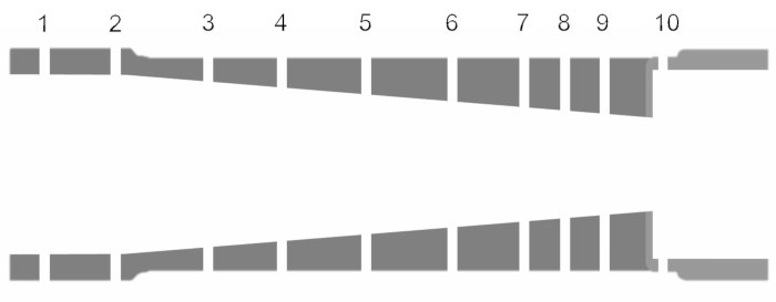
In this demonstration, a nozzle test rig was used, which consisted of a compressed air source that channels high-pressure air through the nozzles being tested, as shown in Figure 5. The flow pressure ranges from 0 - 120 psi and is controlled using a mechanical valve. While the pressures are measured using an external sensor, the mass flow rates in the nozzle are measured by a pair of rotameters placed right before the exhaust of the nozzle test rig.
.css-f1q1l5{display:-webkit-box;display:-webkit-flex;display:-ms-flexbox;display:flex;-webkit-align-items:flex-end;-webkit-box-align:flex-end;-ms-flex-align:flex-end;align-items:flex-end;background-image:linear-gradient(180deg, rgba(255, 255, 255, 0) 0%, rgba(255, 255, 255, 0.8) 40%, rgba(255, 255, 255, 1) 100%);width:100%;height:100%;position:absolute;bottom:0px;left:0px;font-size:var(--chakra-fontSizes-lg);color:#676B82;}
The following constants were used in the analysis: specific heat of dry air, γ: 1.4; reference nozzle area, Ai = 0.0491 in2, and standard atmospheric pressure, Patm = 14.1 psi. Figures 8 and 9 show the variation in pressure ratio and Mach number across the length of the nozzle (normalized based on total nozzle length) for various back-pressure settings for the converging and converging-diverging nozzles, respectively. The mass
Nozzles are commonly used in aircraft and rocket propulsion systems as they offer a simple and effective method to accelerate flow in restricted distances. In order to design nozzles to suit a given application, an understanding of the flow behavior and factors that affect said behavior for a range of flow conditions is essential for designing efficient propulsion systems. In this demonstration, the converging and converging-diverging nozzles - two of the most common nozzle types used in aerospace applications - were tes
Skip to...
Videos from this collection:

Now Playing
Nozzle Analysis: Variations in Mach Number and Pressure Along a Converging and a Converging-diverging Nozzle
Aeronautical Engineering
37.7K Views

Aerodynamic Performance of a Model Aircraft: The DC-6B
Aeronautical Engineering
8.1K Views

Propeller Characterization: Variations in Pitch, Diameter, and Blade Number on Performance
Aeronautical Engineering
26.0K Views

Airfoil Behavior: Pressure Distribution over a Clark Y-14 Wing
Aeronautical Engineering
20.8K Views

Clark Y-14 Wing Performance: Deployment of High-lift Devices (Flaps and Slats)
Aeronautical Engineering
13.2K Views

Turbulence Sphere Method: Evaluating Wind Tunnel Flow Quality
Aeronautical Engineering
8.6K Views

Cross Cylindrical Flow: Measuring Pressure Distribution and Estimating Drag Coefficients
Aeronautical Engineering
16.1K Views

Schlieren Imaging: A Technique to Visualize Supersonic Flow Features
Aeronautical Engineering
11.3K Views

Flow Visualization in a Water Tunnel: Observing the Leading-edge Vortex Over a Delta Wing
Aeronautical Engineering
7.9K Views

Surface Dye Flow Visualization: A Qualitative Method to Observe Streakline Patterns in Supersonic Flow
Aeronautical Engineering
4.8K Views

Pitot-static Tube: A Device to Measure Air Flow Speed
Aeronautical Engineering
48.5K Views

Constant Temperature Anemometry: A Tool to Study Turbulent Boundary Layer Flow
Aeronautical Engineering
7.2K Views

Pressure Transducer: Calibration Using a Pitot-static Tube
Aeronautical Engineering
8.4K Views

Real-time Flight Control: Embedded Sensor Calibration and Data Acquisition
Aeronautical Engineering
10.0K Views

Multicopter Aerodynamics: Characterizing Thrust on a Hexacopter
Aeronautical Engineering
9.0K Views
Copyright © 2025 MyJoVE Corporation. All rights reserved


