Method Article
インクリメントコアのサンプリングとデジタイズのための新しいワークフロー
要約
3Dプリントされたマウントを使用して、木製のマウントに開梱して接着する必要なく、現場でインクリメントコアを固定するプロトコルを紹介します。新しいGSCホルダーは、コアをコアミクロトームに配置して表面を切断し、直接デジタル画像キャプチャに転写することができます。
要約
ここでは、現場でインクリメントコアを取得し、それらを保管してラボに輸送することから、その後の樹木生態学的分析のためのさらなる分析のための年輪のデジタル化までの新しいワークフローを紹介します。この手順では、インクリメントコアに新しいサンプルキャリアを使用します。これらの新しいゲルトナー・シュナイダー・コア(GSC)ホルダーは、3次元(3D)モデリングソフトウェアを使用して設計され、最終的に3Dプリンターでプリントされます。これらのマウントを現場で最初から使用すると、コアミクロトームで直接コアを切断でき、新しい高解像度画像キャプチャシステムを使用して、さらに再配置することなく表面をデジタル化できます。したがって、これらは直接分析に使用できます。このシステムでは、コアやディスクから年輪をデジタル化したり、透過光を使用して長いマイクロセクション(最大40cm)から画像を撮影したりできます。この特徴は、コアミクロトームで切断されたマイクロセクションの擾乱の発生を特定するための年輪生態学的および地形学的アプリケーションにとって特に興味深いものです。
概要
クロスデート技術を適用して年輪を年代測定する原理は、1881年にオーストリアの森林科学者Arthur Freiherr von Seckendorff-Gudentによって初めて導入されました1。20世紀 前半に、この技術は「年輪年代学の父」アンドリュー・エリコット・ダグラスによって再発明され、彼はそれを考古学的遺跡や生きている樹木の年代測定に集中的に適用しました2。
今日、年輪生態学は、年輪年代学の一種の環境フレームとして機能する研究トピックであり、年輪と、時間の生態学的および環境的変化によって引き起こされるそれらの固有の成長変動の研究として定義されています3。年輪生態学研究では、安定同位体、後期木材密度、単一年輪内の細胞特性など、年輪幅の変動以外にも多くの特性を使用して、これらのデータを環境パラメータと相関させ、環境条件が樹木の成長に及ぼす影響を経時的に理解しています4。木材の解剖学的研究と年輪生態学的研究の継続的な統合を通じて、年輪生態学の研究は過去10年間で進化し、過去の気候条件を再構築する上でこれまで以上にバックボーンとなっています5,6,7,8。
サンプル調製と分析に関する技術開発、特に木材解剖学に関する技術開発は、過去10年間で強力であったが9,10,11,12,13,14、サンプリング技術の簡素化15に関しては、ほとんど実質的な進歩はなかった。例えば、音波技術16にもかかわらず、今日まで、木から年輪の特性を抽出するための信頼できる「非破壊的」な方法は存在しなかった。
そのため、年輪関連の研究はすべて、関心のある場所で採取された樹木や低木から採取した木製サンプルに依拠しています。樹木に焦点を当てる場合、標準的な手順は、幹15からコアをインクリメントすることです。
インクリメントコアラーを使用してコアを取ることは、しばしば「非破壊的」手法として表現されます17。ステムからディスクを取るのと比較すると、これは正しいです。それにもかかわらず、このサンプリング手法は、直径約1cmの茎に穴をあけ、その大部分は茎の髄を越えて到達する3。木はこの傷を自然に閉じることができますが、このプロセスは成長反応を引き起こし、創傷のすぐ近くの一般的な構造を変えるだけでなく、真菌性疾患18,19のために穴の周りの既存の木材の多かれ少なかれ激しい変色を引き起こします。ですから、「非破壊的」というよりは「低侵襲的」と呼ぶべきでしょう。
インクリメントコアを取る技術は、最近、機械式ドリルを使用する能力を通じて進化し、特に木材の解剖学的分析15において、より高品質のサンプルをもたらしました。この手順は、手動のコアリングと比較して、現場での時間を大幅に節約します。変わらなかったのは、木からの抽出からラベリング、輸送用の保管、およびさまざまな可能な分析技術のためのラボでのコアの準備まで、コアの取り扱い手順でした。
芯は、輸送中に芯が折れるのを防ぐために、プラスチックや紙製のストローなどの安定した容器に詰める必要があります。芯のラベリングは、柔らかい鉛筆を使用して芯に直接行うか、(より頻繁に)各ストローの外側で行います。プラスチック容器を使用する場合は、真菌の拡散を避けるために、短時間でコアを取り出す必要があります。そのため、コアをコンテナから再度取り出す必要があります。コアを安定させ、乾燥開始時にコアが曲がらないようにするには、コアをマウントに固定する必要があります。これは、その後のさらなる分析のための表面処理にも役立ちます。その際、ラベルをそれぞれのマウントに転写する必要もあります。標準的な手順は、木製の台紙にコアを接着するか、段ボールのリルにテープで固定することです。それらを木製の台紙に接着することは、最も頻繁に使用される技術です。この手順は、コアの安定化、研磨、または切断に最適ですが、潜在的な化学的分析、同位体分析、さらには木材の解剖学的分析に関していくつかの欠点があります。もう 1 つの欠点は、必要な時間にもかかわらず、各コアのラベルが新しいマウントにエラーが起こりやすいことです。
年輪年代学では、正確な年代測定の基盤としての年輪幅の測定は、すべての年輪生態学的研究のバックボーンです20。多くのラボでは、双眼鏡が取り付けられたLintab21などの測定テーブルを使用した手動測定にまだ依存していますが、フラットベッドスキャナーを使用してコア表面をデジタル化し、CooRecorder22やWinDENDRO23などのソフトウェアを使用してリング幅を測定する傾向があります。残念ながら、これらのスキャナー、たとえば広く使用されているEpson Expression 10000XLは、アーリーウッドまたはレイトウッドの気管として構造を明確に描写するのに十分な解像度を持っていません(図1)。このため、得られた画像は、双眼鏡24,25を使用して元のコアに戻ることなく正確なクロスデート手順に重要な、非常に狭いリングや密度の変動などの困難な構造を認識するのには適していない。
年輪科学10において、適切な画像解析を行うためには、高い画像解像度が必須の前提条件であることから、WSL(Skippy、https://www.wsl.ch/en/services-produkte/skippy/)では、デジタルカメラを用いてコア表面の年輪をデジタル化する新しい画像キャプチャシステムを開発しました。その結果、既存のフラットベッドスキャナーよりも高い解像度の画像が得られました。このシステムは、2007年に開発されたATRICSシステム26のアイデアに基づいています。最近では、スキッピーに匹敵するシンプルだが効率的な画像キャプチャシステムが、自己組み立てキット27として発表された。
年輪のデジタル化、つまり反射光画像キャプチャは、増分コアまたはディスクの高解像度画像を作成するための重要なステップであり、時間効率の高いデジタルベースの年輪幅測定をサポートします。WSLで開発されたシステムでは、透過光を使用して長いマイクロセクション(最大40cm)から画像を撮影することもできます。この追加機能は、例えば、マイクロセクションにおける反応木材の発生を特定するための年輪地形学的アプリケーションにとって興味深いものです。
この研究では、現場やラボでのコアの取り扱いプロセスを容易にするためのプロトコルを提示します。提示された新しい技術のベースは、再利用可能なマウントです。新しいGSCホルダー GärtnerSchneiderC鉱石(GSC)ホルダーは、3Dモデリングソフトウェアを使用して設計され、3Dプリンターで印刷されました。GSCホルダーは、現場で取り込んだコアを再梱包したりラベルを付け直したりすることなく、簡単に取り扱うことができます。また、コアの準備された表面をデジタル化するための効率的な新しいシステムも紹介します。このプロトコルは、現場でのコアの採取からサンプル調製、その後の分析のためにコア表面をデジタル化し、最終的にアーカイブに保存するまでの手順全体に及びます。
プロトコル
1. GSCホルダーの作成
- ホルダーの3Dモデルを、3Dプリンターに対応したスライサープログラムで開きます。3Dプリンターで読み込める印刷ファイル(この場合は「*.gcode」ファイル)を作成します。
注:3Dモデルは、任意の3Dモデリングソフトウェアを使用して設計できます。 - メモリカードまたはUSBスティックを使用してプリントファイルを3Dプリンターに転送し、3Dプリンターで印刷ファイルをアクティブにします。
- ホルダーが印刷されたらすぐに、ホルダーが室温(RT)まで冷えるまで待ちます。次に、ホルダーが貼り付けられているプレートをプリンターから取り外し、フォームが表面から離れるまでプレートを少し曲げます。
- ホルダーから余分な糸やアタッチメントをすべて取り外します。
注意: 一度に印刷するホルダーの数は、プリンターのサイズによって異なります。プレート寸法が36cm×36cmの3Dプリンターでは、長さ35cmのホルダーを1回で約30個プリントできます。30個のホルダーを印刷するのに必要な時間は、デバイスによって異なります。平均して、これは約8時間(夜間印刷)で完了する必要があります。
2. 現場でのインクリメントコアの抽出、安定化、輸送
- トルクブースターとインクリメントコアラーを装備したコードレスドリルを取り、コアリングの位置を選択し、コアラーをステムの成長軸に垂直に配置します。
注意: コードレスドリルを使用せずに、インクリメントコアラーを使用して手動で同じことを行うことができます。 - コアラーがステム直径の少なくとも半分に達するまでコアリングを開始します。上記のように、エクストラクター(コアラーと同じ長さ)をコアラーの横に保持して、深さを確認します。
- コードレスドリルを使用する場合は、ドリルを取り外し、ハンドルをコアラーに置き(インクリメントコアラーを手動で使用する場合はすでにそうです)、開いた面を上に向けてエクストラクターを取り、コアラーに完全に挿入します。
- インクリメントコアラーを後方に回す(1回転する)と、コアをステムから切り離します。コアを含むエクストラクターを取り出します。
- エクストラクターからコアを取り外します。コアをホルダーに配置するときは、コアのファイバー方向を確認して、ファイバーの直立した向きを確認してください。
注:ファイバーの方向は、コアの両端とコアの側面で確認できます。このためには、コアを光に当てて、側面が輝くまで回します。これは、こちら側では、放射状の細胞壁が縦方向に切断され、コアの他の部分とは異なる方法で光を反射するために発生します。 - ファイバー方向を直立させて、コアをホルダーの上に置きます。コアがホルダーに滑り込むまで、すべての指でコアの上部を押します。
- ホルダーの側面にある芯に柔らかい鉛筆でラベルを貼り、ガラスにも書き込めるようにします。
注意: 書き込みは、後で一般的なゴムで取り外すことができます。 - 芯のあるホルダーを輸送ボックスに入れ、カバーを閉じます。
3. ラボでマウントされたコアの準備
- オプション:マウントされたコアをパラフィンに埋め込むことで、マイクロセクショニングが可能になります。
- 真空ポンプ接続用のバルブが取り付けられた蓋付きのスチールボックスをホットプレートに置き、パラフィンを約2cmまで充填し、完全に溶けるまで待ちます。
- 取り付けられたコアをトランスポートボックスから取り出します。ホルダーをコアをそのまま流動パラフィンに入れ、蓋を閉めます。
- 真空ポンプを始動し、容器に一定の軽い真空を当てて、約2時間待ちます。ホルダーのオープン構造により、パラフィンは追加の障壁なしにコアを貫通できます。
- 真空ポンプを停止し、蓋を開けます。コアの入ったホルダーを取り出し、グリッドに置き、冷まします。
- 必要に応じて、ホルダーの側面から余分なパラフィンを取り除きます。
- コアサーフェスの準備
- 取り付けられたコアを輸送ボックスまたはパラフィンバスから取り出します。コア付きのホルダーをそのままコアミクロトームのサンプルホルダーに置きます。リングのレイトウッドがブレードを向くようにコアを向けてください。
- コアホルダーが完全に固定されるまで、サンプルホルダーのネジを締めます。
- コアがブレードにわずかに触れるまで、サンプルホルダーを持ち上げます。コアの全範囲にわたってブレードを引っ張って、上部の最初の部分を切り取ります。
- ナイフをコアの後ろに押し戻し、サンプルホルダーを数ミクロン持ち上げ、幅が少なくとも2〜3mmの平面が得られるまで手順を繰り返します。
- 意図したとおりに表面を切断したらすぐに、ミクロトームのサンプルホルダーからコアホルダーを取り外します。
注:コアミクロトームでコアを切断し、表面がきれいでまっすぐで、セルがほこりで満たされていないため、サンディングしないことをお勧めします。
4. コアサーフェスのデジタイズ
- ここでWSL-Skippyシステムが示されているように、プレーンコア面を持つコアホルダーを画像キャプチャシステムのテーブルに置きます。
- コアホルダーをテーブルまたはカメラの移動方向に合わせてください。
- コアホルダーをカメラの下に置き、最も外側のリングがカメラ対物レンズの下の view 中央になるようにします。
- コアの開始点の隣にスケールを置き、キャリブレーションのために画像を撮ります。
注:これは、多数のコアのイメージを連続して行う場合に1回だけ行う必要があります。 - ソフトウェアでコアの長さを定義し、画像キャプチャ プロセスを開始します。最後の画像が撮影されると、テーブルは開始位置に戻ります。
- サンプルをテーブルから取り出し、次のホルダーをカメラの下に置き、すべてのコアが撮影されるまでコアの長さを定義して前述の手順を繰り返します。
- PTGuiなどの(歪みのない)スティッチングソフトウェアを使用して、単一の画像をコア表面の1つの最終画像に結合します。
5. コアの保管
- 解析したコアをホルダーに取り、3Dプリンターでプリントしたポータブルストレージラックに入れます。
- ラックにラベルを付けて、外部からコアを識別します。
- ラックは、棚またはその他の使用可能なアーカイブに保管します。
結果
GSCホルダー
コアホルダーは(デフォルトとして)35cmの長さでプリントされており、これは使用する3Dプリンターの最大プリントサイズ(Original Prusa XL、ビルドボリューム36cm×36cm×36cm)にほぼ対応しています。より長いコアを使用する場合は、すべてのホルダーの両端にあるくぼみを介して小さな接続部品でホルダーを接続することにより、ホルダーを追加のホルダーで拡張できます(図2A)。
フィールドワークを行う場合、芯を直接ホルダーに保管する時間は、単に芯をストローなどの包装材に入れるのに匹敵します。コアをホルダーに押し込む前に、各コアのファイバー方向を尊重する必要がありますが(図2)、この追加時間はわずか数秒であり、レンズを使用してサポートできます。私たちの経験では、必要な余分な時間 (もしあれば) は、10 個のコアで合計すると約 1 分になります。この最小限の延長時間は、壊れたコアも指します。折れた芯を一つ一つ藁に詰めるのではなく、これらの芯を一つ一つホルダーに入れて押し込むだけです。
現場やラボへのコアの安全な輸送を保証するために、コアを含むホルダー用の特別な輸送ボックスを設計し、印刷しました(図3)。ホルダーは、ホルダーの両端のくぼみに正確に収まる小さな膨らみによって安定しているボックスに簡単に配置できます。その後、ボックスの側面の溝に押し込まれるカバーでボックスを閉じることができます。
新しいホルダーの真の利点は、実験室で明らかになります。ストロー(または他の容器)からコアを取り出し、手がかりを持って木製のマウントを準備し、マウントにコアを固定し、ラベルを新しいマウントに貼り付け、接着剤が乾燥して安定した状態でさらに処理できるようになるまで少なくとも数時間待つ代わりに、ホルダーのコアを直接(i)コアミクロトームに固定してプレーンな表面を切断するか、(ii)サンディングで直接サンディングすることができますそれ以上の準備プロセスを必要としない機械。ラベルを新しいマウントに転送する必要がないため、特に伝送エラーの可能性を回避できます。
ホルダーは任意のコア径に設計できるため、「標準」の5mmコアに必要であろうと、10mmまたは12mmコアに必要であろうと、同位体やその他の化学分析に必要かどうかは関係ありません。
同位体分析や化学分析に関連して、ホルダーの利点は、接着剤や固定媒体を必要とせずにコアが固定されることです。そのため、コアは汚染されておらず、より具体的な分析のためにホルダーから簡単に取り外すことができます。また、木材の解剖学的解析に関しては、ホルダーからコアを簡単に取り外すことができるため、マイクロセクションを準備するためのコアを簡単に取り扱うことができます。
オプションでホルダーに固定されたコアを埋め込むことができるため、細胞壁が薄い細胞は切断中に壊れやすいため、敏感な構造を安定させることができます。多くの場合、コアをパラフィンに埋め込んで安定化させることは、単にコーンスターチ溶液を追加するよりも効率的です。
また、後の検査や再解析のためにコアを保管する必要がある場合にも、別の利点があります。ホルダーは特別に設計されたラック(図4)に設置でき、輸送ボックス内の保管に匹敵する3Dプリンタを使用して印刷することもできます。コア付きのGSCホルダーは、そのままラックに収納でき、どこにでも収納できます。ラックの幅、つまり1つのラックに固定できるコアの数は、棚や保管室のスペースによって異なります。ラックモデルは、特定のニーズに合わせて適合させ、それに応じて印刷することができます。
コアまたはディスク表面のデジタイズ
WSLで開発された画像キャプチャシステム(図5)は、年輪のデジタル化(自動画像キャプチャ)を可能にし、インクリメントコアまたはディスクの高解像度画像を作成して、時間効率の良いデジタルベースの年輪幅測定をサポートします。このシステムは、ネジ付きロッドに固定されたプレートで構成され、サンプルを61MPカメラ(Sony Alpha 7R IV)の対物レンズ(Sony FE 90 mm f / 2.8 Macro)の下に0.1〜1cmの事前定義されたステップで移動させます。画像は、カメラのオートフォーカスシステムを使用して撮影され、焦点が合った単一の画像を保証します。カメラの解像度により、SilverFast解像度ターゲット(USAF 1951)を使用してテストされた6500dpiの各画像の実際の解像度が可能になります。これは、指定された解像度が4800dpiのフラットベッドスキャナーの公式解像度と比較すると、少し低く聞こえるかもしれません。しかし、Epson XLスキャナーで撮影した同じターゲットの画像を4800dpiの解像度でテストしたところ、結果の画像は実際の解像度が1825dpiしか示しませんでした(図6)。画像の高解像度により、単一細胞を鮮明に見ることができ、これにより、画像にキャプチャされたリング境界を明確に定義できます(図7)。使用するコアやディスクの表面が十分に準備されていれば、元のサンプルに戻って構造を再度確認する必要はありません。単一の画像をスティッチングした後、得られたコア画像は、好ましい分析ソフトウェアを使用して分析できます。
また、この画像キャプチャシステムでは、透過光を使用して、最大40cmの長さのマイクロセクションから画像を撮影することもできます。この特徴は、例えば、反応木材の発生や、全体の木のコアの微小な部分における他の特定の特徴を特定するための年輪地形学的なアプリケーションにとって興味深いものです(図8)。
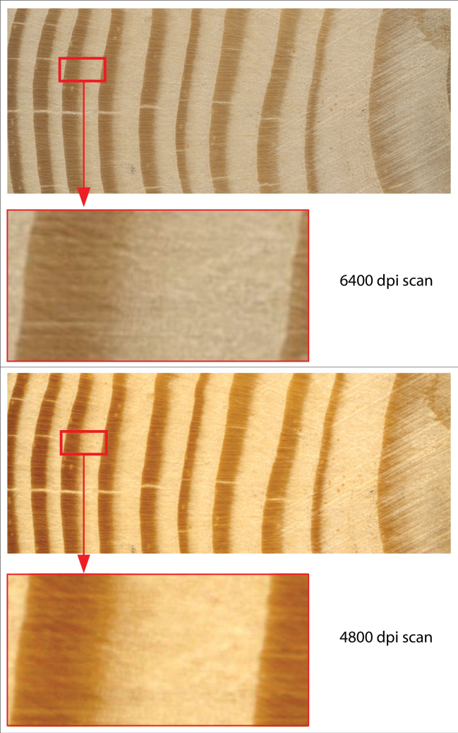
図1: Larix decidua ミルのスキャン画像。 フラットベッドスキャナーを使用してさまざまな解像度でスキャンされた年輪。 この図の拡大版を表示するには、ここをクリックしてください。
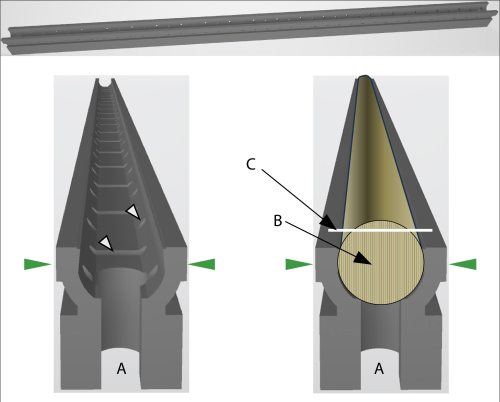
図2:GSCホルダーの概略図(A)ホルダーの両端の開口部により、2つのホルダーを小さなポールで接続して、長いコアを固定できます。緑色の矢印は、ホルダーをコアミクロトームに固定したときの圧力方向を示しています。左:白い矢印は、空気または液体(埋め込み用)の循環を可能にする開口部を示しています。右:芯を押し込んだGSCホルダー。(B)コアの繊維方向は直立している必要があります。(C)白い線はコアの切断面を示しています。この図の拡大版を表示するには、ここをクリックしてください。
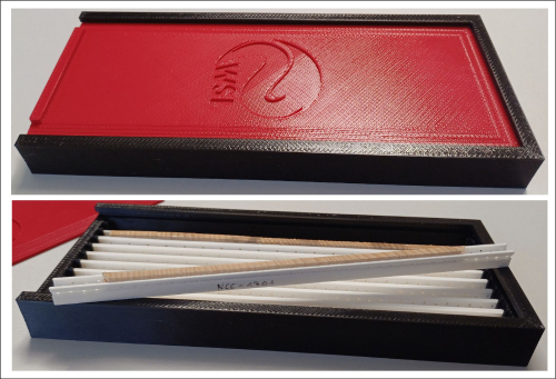
図3:GSCホルダーを保管し、コアを現場に保管および輸送するための輸送ボックス。この図の拡大版を表示するには、ここをクリックしてください。
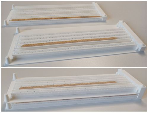
図4:アーカイブに最終的なストレージとしてGSCホルダーを配置するためのストレージフレーム。 フレームを積み重ねてスペースを節約できます。 この図の拡大版を表示するには、ここをクリックしてください。
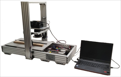
図5:WSLで開発された画像キャプチャシステム。この図の拡大版を表示するには、ここをクリックしてください。
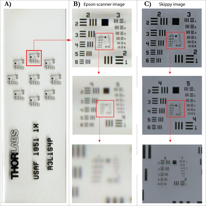
図6:フラットベッドスキャナーと画像キャプチャシステム間の画像解像度の比較(A)SilverFast解像度ターゲット(USAF 1951)。(B)指定された解像度4800dpi(補間)のフラットベッドスキャナーでスキャンされた画像と、以下のそれぞれのセクションの拡大。(C)画像キャプチャシステムで撮影した画像と、以下の各セクションの拡大。この図の拡大版を表示するには、ここをクリックしてください。
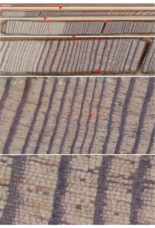
図7: Larix decidua Mill.インクリメントコアの合成画像(上の画像)と下のそれぞれのセクションの拡大。 合成物の単一画像は、画像キャプチャシステムで撮影されました。 この図の拡大版を表示するには、ここをクリックしてください。
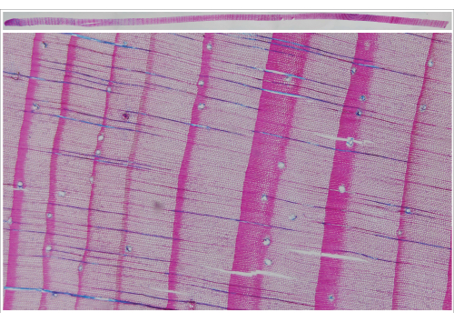
図8:インクリメントコア全体のマイクロセクション(Larix decidua Mill.)とそれぞれのセクション拡大の合成画像。 合成物の単一画像は、画像キャプチャシステム(透過光)で撮影されました。 この図の拡大版を表示するには、ここをクリックしてください。
ディスカッション
樹木の解剖学を樹木生態学的研究に含めることで、これらの研究は過去の環境条件の新しく詳細な分析に広く開かれました28,29,30。これらの新しい手法は、分析作業、つまり目的のデータを生成するために必要なラボ時間も強化しました。実験室での作業を最適化し、木材解剖学的技術9,12,13,15,30に関して実験室で必要な時間を短縮するための多くの試みがなされてきた。しかし、これらの研究のために行われたコアの取り扱い、準備、および保管の一般的な手順を容易にするための努力はほとんど行われていません。
3Dプリンティングは、この点で新たな可能性を提供します9。新しい3Dプリントされたコアホルダーは、この手順全体を簡素化し、時間を短縮し、より効率的にする最初の試みです。
プラスチック製ストロー31,32または同等の容器に保存されたコアは、コアの外側(およびすぐに内側)で真菌が発生するのを防ぐために取り出す必要がありますが、GSCホルダーに固定されたコアはそのままにしておくことができます。この点までは、紙製ストロー33に収納するのと同等である。
その利点は、(i)藁(または他の容器)から芯を取り外す、(ii)芯を木製の台紙に接着するか、ケーブルサポートとして他の物体に固定する、そして(iii)各芯に使用されるそれぞれのコードを転送するというエラーが発生しやすいプロセスを実行するとすぐに明らかになります。 不要になります。
GSCホルダーのオープン構造により、プラスチック容器に保管する場合のように、真菌の侵入のリスクなしにコアを保管することができます。上述したように、ホルダーは、構造を安定させるためにパラフィンに包埋することも可能にする。それにもかかわらず、この「単純な」埋め込みは、マイクロコア35に対して行われるように、サンプルをパラフィンブロックに埋め込むためにカセットを使用する一般的な埋め込み手順と比較することはできない。この単純な技術は、マイクロ切片36を切断する際にコーンスターチを塗布することにかなり匹敵する。これにより、細胞がより安定し、切断手順中に細胞が破損するのを防ぐことができますが、単にコーンスターチを追加するよりも時間がかかります。この形式の埋め込みでは、コア全体がブロックに埋め込まれているかのように安定することはありません。コアが壊れると、セクションも壊れます。GSCホルダーはコアミクロトーム37に収まるため、その後のデジタル化プロセスのための表面の準備には数分しかかかりません。
年輪をデジタル化するプロセスでは、青色強度測定38,39に頻繁に使用されるフラットベッドスキャナーの適用は、結果として得られる画像の品質がかなり低かったため、年輪構造のより詳細なビューに関しては満足のいくものではなかった。これらの画像では、針葉樹の一般的な(幅の広い)リングの境界が見えましたが、狭いリングや密度の変動さえも識別することはほぼ不可能でした。
X線CT40など、年輪を高解像度でデジタル化する魅力的な新しい試みがありますが、高解像度のデジタルカメラを使用することは、さらなる測定のために高品質の画像を生成するための最も効率的で費用対効果の高い方法です。
開示事項
著者らは、競合する金銭的利益がないことを宣言します。
謝辞
著者は、新しいホルダーを作成するという考えを支持してくれたJussi Grießinger教授に感謝したいと思います。
資料
| Name | Company | Catalog Number | Comments |
| Core-microtome | WSL | https://www.wsl.ch/en/services-produkte/microtomes/ | Microtome to cut micro sections from increment cores |
| Epson Expression 10000XL | EPSON | https://epson.com/Support/Scanners/Expression-Series/Epson-Expression-10000XL---Graphic-Arts/s/SPT_E10000XL-GA | flatbed scanner |
| GSC holder | WSL | in-house | 3D printed mount to fix cores for transport, preparation, analyses, and storage |
| Skippy image capturing system | WSL | https://www.wsl.ch/en/services-produkte/skippy/) | Image capturing system developed at WSL equiped with a 61 MP camera (Sony Alpha 7R IV and Sony FE 90mm f/2.8 Macro lens) |
参考文献
- Wimmer, R. Arthur Freiherr von Seckendorff-Gudent and the early history of tree-ring crossdating. Dendrochronologia. 19 (1), 153-158 (2001).
- McGraw, D. J. Andrew Ellicott Douglass and the giant sequoias in the founding of dendrochronology. Tree-Ring Res. 59 (1), 21-27 (2003).
- Schweingruber, F. H. . Tree Rings and Environment: Dendroecology. , (1996).
- Amoroso, M. M., Daniels, L. D., Baker, P. J., Camarero, J. J. . Dendroecology: Tree-Ring Analyses Applied to Ecological Studies (Vol.231). 231, (2017).
- Lopez-Saez, J., Corona, C., Von Arx, G., Fonti, P., Slamova, L., Stoffel, M. Tree-ring anatomy of Pinus cembra trees opens new avenues for climate reconstructions in the European Alps. Sci Total Environ. 855, 158605 (2023).
- Björklund, J., et al. Fennoscandian tree-ring anatomy shows a warmer modern than medieval climate. Nature. 620 (7972), 97-103 (2023).
- Camarero, J. J., Colangelo, M., Rodriguez-Gonzalez, P. M. Tree growth, wood anatomy and carbon and oxygen isotopes responses to drought in Mediterranean riparian forests. Forest Ecol Manag. 529, 120710 (2023).
- Huang, R., Xu, C., Grießinger, J., Feng, X., Zhu, H., Bräuning, A. Rising utilization of stable isotopes in tree rings for climate change and forest ecology. JForestry Res. 35, 13 (2024).
- Schneider, L., Gärtner, H. Additive manufacturing for lab applications in environmental sciences: pushing the boundaries of rapid prototyping. Dendrochronologia. 76, 126015 (2022).
- Björklund, J., et al. Scientific merits and analytical challenges of tree-ring densitometry. Rev Geophys. 57, 1224-1264 (2019).
- Katzenmaier, M., Garnot, V. S. F., Björklund, J., Schneider, L., Wegner, J. D., von Arx, G. Towards ROXAS AI: Deep learning for faster and more accurate conifer cell analysis. Dendrochronologia. 81, 126126 (2023).
- Gärtner, H., Lucchinetti, S., Schweingruber, F. H. A new sledge microtome to combine wood anatomy and tree-ring ecology. IAWA J. 36 (4), 452-459 (2015).
- Gärtner, H., et al. A technical perspective in modern tree-ring research - how to overcome dendroecological and wood anatomical challenges. J Vis Exp. 97 (e52337), (2015).
- Gärtner, H., Banzer, L., Schneider, L., Schweingruber, F. H., Bast, A. Preparing micro sections of entire (dry) conifer increment cores for wood anatomical time-series analyses. Dendrochronologia. 34, 19-23 (2015).
- Gärtner, H., Schneider, L., Lucchinetti, S., Cherubini, P. Advanced workflow for taking high-quality increment cores - new techniques and devices. J Vis Exp. (193), e64747 (2023).
- Wang, X. Acoustic measurements on trees and logs: a review and analysis. Wood Sci Technol. 47, 965-975 (2013).
- Steenkamp, C. J., Van Rooyen, M. W., Van Rooyen, N. A non-destructive sampling method for dendrochronology in hardwood species. South Afr For J. 186, 5-7 (1999).
- Toole, E. R., Gammage, J. L. Damage from increment borings in bottomland hardwoods. J For. 57, 909-911 (1959).
- Grissino-Mayer, H. D. A manual and tutorial for the proper use of an increment borer. Tree-Ring Res. 59 (2), 63-79 (2003).
- Griffin, D., et al. Gigapixel macro photography of tree rings. Tree-Ring Res. 77, 86-94 (2021).
- . LINTAB-Precision ring by ring Available from: https://rinntech.info/products/lintab/ (2003)
- . Regent Instruments Available from: https://regentinstruments.com (2024)
- De Micco, V., et al. Intra-annual density fluctuations in tree rings: How, when, where, and why. IAWA J. 37, 232-259 (2016).
- Edwards, J., et al. Intra-annual climate anomalies in northwestern North America following the 1783-1784 CE Laki eruption. J Geophys Res Atmos. 126, e2020JD033544 (2020).
- Levanič, T. ATRICS-A new system for image acquisition in dendrochronology. Tree-Ring Res. 63 (2), 117-122 (2007).
- García-Hidalgo, M., et al. CaptuRING: A do-it-yourself tool for wood sample digitization. Methods Ecol Evol. 13 (6), 1185-1191 (2022).
- Rodriguez, D. R. O., et al. Exploring wood anatomy, density and chemistry profiles to understand the tree-ring formation in Amazonian tree species. Dendrochronologia. 71, 125915 (2022).
- Gärtner, H., Farahat, E. Cambial activity of Moringa peregrina (Forssk.) Fiori in arid environments. Front Plant Sci. 12, 760002 (2021).
- Gärtner, H., Lucchinetti, S., Schweingruber, F. H. New perspectives for wood anatomical analysis in dendrosciences: the GSL1-microtome. Dendrochronologia. 32, 47-51 (2014).
- Maeglin, R. R. . Increment Cores: How to Collect, Handle, and Use Them (Vol. 25). , (1979).
- Agee, J. K., Huff, M. H. . The Care and Feeding of Increment Borers. , (1986).
- Phipps, R. L., , . . Collecting, Preparing, Crossdating, and Measuring Tree Increment Cores (No. 85-4148). , (1985).
- Cole, D. M. . Protection and Storing Increment Cores in Plastic Straws. 216, (1977).
- Rossi, S., Anfodillo, T., Menardi, R. Trephor: a new tool for sampling microcores from tree stems. IAWA J. 27 (1), 89-97 (2006).
- Schneider, L., Gärtner, H. The advantage of using a starch based non-Newtonian fluid to prepare micro sections. Dendrochronologia. 31, 175-178 (2013).
- Gärtner, H., Nievergelt, D. The core-microtome: A new tool for surface preparation on corse and time series analysis of varying cell parameters. Dendrochronologia. 28 (2), 85-92 (2010).
- McCarroll, D., Pettigrew, E., Luckman, A., Guibal, F., Edouard, J. L. Blue reflectance provides a surrogate for latewood density of high-latitude pine tree rings. Arct Antarct Alp Res. 34 (4), 450-453 (2002).
- Björklund, J., Seftigen, K., Kaczka, R. J., Rydval, M., Wilson, R. A standard definition and terminology for Blue Intensity from conifers. Dendrochronologia. 85, 126200 (2024).
- Van den Bulcke, J., et al. Advanced X-ray CT scanning can boost tree ring research for earth system sciences. Ann Bot. 124 (5), 837-847 (2019).
転載および許可
このJoVE論文のテキスト又は図を再利用するための許可を申請します
許可を申請さらに記事を探す
This article has been published
Video Coming Soon
Copyright © 2023 MyJoVE Corporation. All rights reserved