
JoVE 비디오를 활용하시려면 도서관을 통한 기관 구독이 필요합니다. 전체 비디오를 보시려면 로그인하거나 무료 트라이얼을 시작하세요.
Method Article
A Bending Test for Determining the Atterberg Plastic Limit in Soils
요약
The traditional standardized test for determining the plastic limit in soils is performed by hand, and the result varies depending on the operator. An alternative method based on bending measurements is presented in this study. This allows the plastic limit to be obtained with a clear and objective criterion.
초록
The thread rolling test is the most commonly used method to determine the plastic limit (PL) in soils. It has been widely criticized, because a considerable subjective judgment from the operator that carries out the test is involved during its performance, which may affect the final result significantly. Different alternative methods have been put forward, but they cannot compete with the standard rolling test in speed, simplicity and cost.
In an earlier study by the authors, a simple method with a simple device to determine the PL was presented (the "thread bending test" or simply "bending test"); this method allowed the PL to be obtained with minimal operator interference. In the present paper a version of the original bending test is shown. The experimental basis is the same as the original bending test: soil threads which are 3 mm in diameter and 52 mm long are bent until they start to crack, so that both the bending produced and its related moisture content are determined. However, this new version enables the calculation of PL from an equation, so it is not necessary to plot any curve or straight line to obtain this parameter and, in fact, the PL can be achieved with only one experimental point (but two experimental points are recommended).
The PL results obtained with this new version are very similar to those obtained through the original bending test and the standard rolling test by a highly experienced operator. Only in particular cases of high plasticity cohesive soils, there is a greater difference in the result. Despite this, the bending test works very well for all types of soil, both cohesive and very low plasticity soils, where the latter are the most difficult to test via the standard thread rolling method.
서문
Liquid Limit (LL) and Plastic Limit (PL) are the two most important soil consistency limits of those defined by Atterberg in 19111. LL marks the boundary between liquid and plastic states, and PL between plastic and semisolid states. LL is obtained around the world according to several standards through the Casagrande method2,3 or the penetration test4. Both methods are conducted mechanically by devices; thereby, minimal operator interference is involved. In the case of PL, the so called "thread rolling test" is the most popular and standardized method for its determination2,5. This test is based on rolling soil into 3 mm threads by hand until the operator considers the soil to be crumbling. For this reason it has been widely criticized because the skill and judgment of the operator play a critical role in the outcome of the test. Standard rolling test is importantly affected by many uncontrolled factors, such as the pressure applied, the contact geometry, the friction, the speed of rolling, the size of the sample and the type of soil6,7. The American Society for Testing and Materials (ASTM) developed the ASTM D 4318 standard which includes a simple device in order to minimize the operator interference2,8, however significant differences have been reported in some soils when comparing the manual rolling test against the test performed by the ASTM D4318 device9.
PL is a very important parameter for geotechnical purposes, since Plasticity Index (PI) is obtained from it (PI = LL - PL); PI is used to classify the soil in accordance with the Plasticity Chart shown in ASTM D 248710, based on the research of Casagrande11,12. Errors in the PL affect negatively this classification13, and for this reason, a new test for PL determination is required.
Pfefferkorn test, cone penetrometer, capillary rheometer, torque rheometer or stress-strain tests are some examples of alternative methods for measuring soil plasticity14, but these are not adequate to obtain the PL. With the special instance of fall cone tests, a large number of researchers have attempted to define a new methodology for PL determination using different penetrometer designs15-20, but without reaching any real agreement. Furthermore, all of it is based on the assumption that the shear strength at the PL is 100 times that at the LL21, which is not true22.
Barnes23,24 developed an apparatus that emulated the rolling conditions of soil cylinders in an attempt to lay down a clear criterion for PL determination. Nevertheless, some shortcomings are identified with this approach, such as its complexity, test duration and mainly the questionable means of calculating the PL25. The success of the standard rolling test lies in its simplicity, quick performance and low cost, so no alternative method will be able to replace it, unless it meets these three requirements and other ones, such as high accuracy and low operator interference.
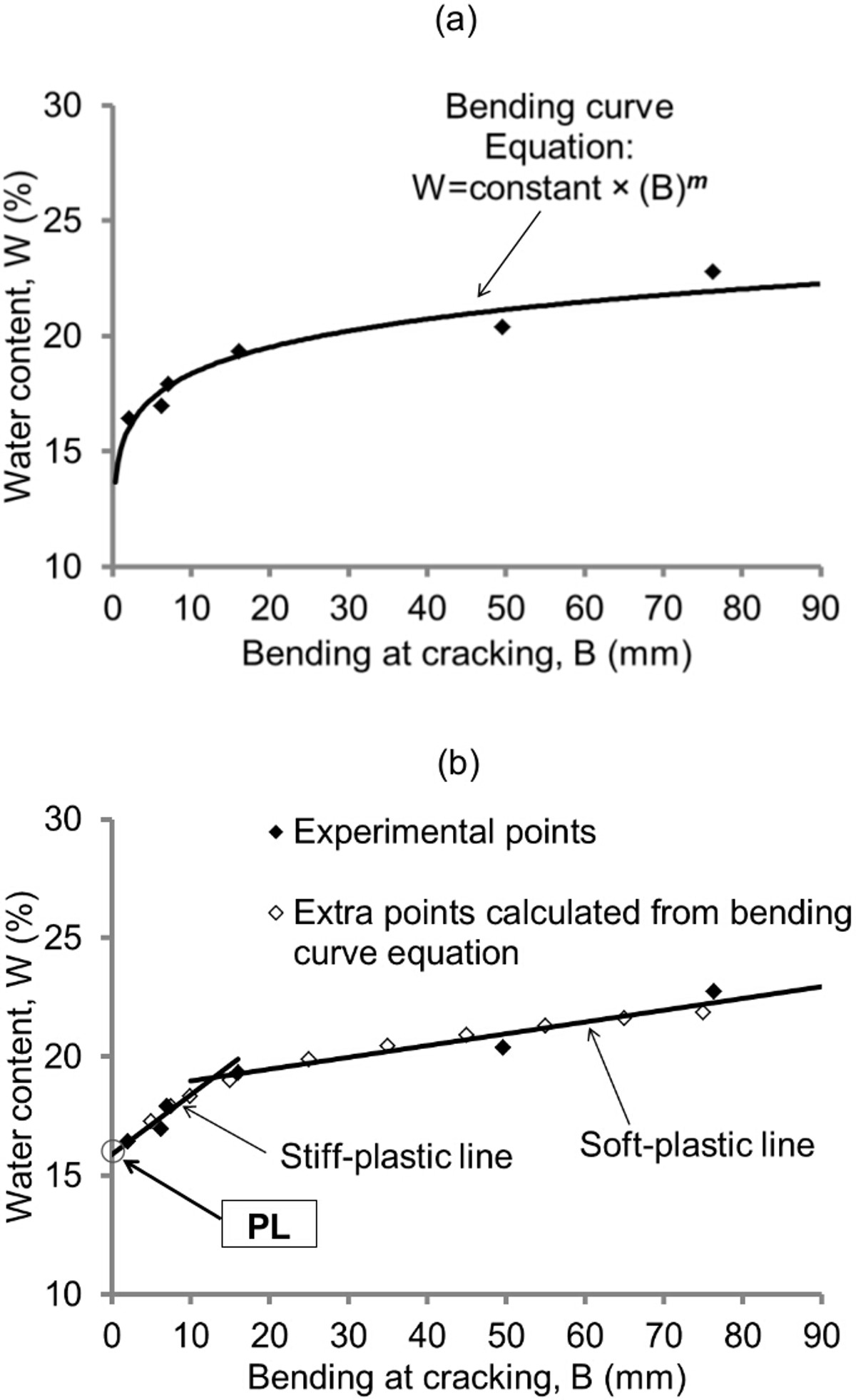
In a previous study by the authors, a new PL approach was proposed25: the original thread bending test (or simply bending test) allowed the PL to be obtained from a graph in which it was represented the relationship between water content and bending deformations. The authors obtained and plotted several experimental points for each soil (the protocol followed to get these points was the same as that indicated in the present paper), so that the correlation of the points could be defined in two ways without compromising in any way the correct definition of the point path: as a parabolic curve, named the bending curve (Figure 1A), and as two intersecting straight lines with different slope, named the stiff-plastic line and the soft-plastic line. The stiff-plastic line is the steepest one, and PL was calculated from it as the moisture percentage corresponding to the cutoff point of this with the y-axis (Figure 1B). In this cutoff point the bending produced is zero, which is in accordance with the concept of plastic limit, i.e., PL is the moisture content at which the soil is not capable of withstanding deformations below this threshold (semisolid state) but it does bear them above it (plastic state). Although in the original study, the PL could not be obtained directly by the bending curve (this does not intersect the y-axis), this line was very useful because considering that the bending curve and the intersecting lines follow very similar paths, the bending curve equation obtained from the experimental data was used to obtain extra points to, firstly, correct any deviation, and, secondly, to carry out the test with just a few points as shown in Figure 1B.

Figure 1. Graphical representation of the B-W points in a tested soil by the original bending test. (A) The correlation of the points is represented as a parabolic curve, named the bending curve whose equation is included. (B) The correlation of the points is defined by two intersecting lines and other extra points are added (they were calculated from the bending curve equation). B values are obtained as B=52.0-D (where D is the average distance measured between the tips at the time of cracking in mm) and the PL is calculated as the water content corresponding to the cutoff point of the stiff-plastic line with the y-axis. This figure has been modified from Moreno-Maroto & Alonso-Azcárate25. Please click here to view a larger version of this figure.
All the results were in excellent agreement with those achieved through the traditional thread rolling method by a highly experienced operator. However, the original bending test remained slower than the standardized thread rolling test. In an attempt to further economize test time, a one-point version was put forward. It was based on the average bending slope (m) obtained in the 24 tested soils, which was 0.108 (m is the slope of the bending curve when it is represented in double logarithmic scale; m appears on the bending curve equation in Figure 1A). By means of an equation where this factor was included, both the stiff-plastic and soft-plastic lines were graphically drawn, and thus the PL was estimated. These results were also highly correlated with both the multi-point bending test and the standard rolling test. In spite of this one-point version being even faster than the traditional test, the PL calculation was more complex because plotting was necessary. For this reason, on the basis of statistical criteria a new equation for PL calculation has been developed in this study, so that plotting is not required and results can be achieved with only one point, whereas the experimental protocol is the same as the original bending test. This new version meets the necessary requirements to replace the outdated thread rolling method.
프로토콜
1. Collect, Dry and Sieve the Test Sample
- Collect a soil sample in the field (use a shovel or a trowel) and store it in a polyethylene bag.
Note: The volume of the sample varies depending on the type of soil: in fine soils (clays and silts) between 100 and 1,000 g is generally sufficient, but in sandy soils and those containing gravel and pebbles, large amounts may be required, from a few to several kg. - Reduce the sample by quartering in the laboratory if this is too voluminous (use a soil splitter if necessary).
- Place the sample on a tray and dry the soil at a temperature not exceeding 60 °C.
Note: Both oven-drying and air-drying are valid. Even the drying step may be ignored in very fine soils if they contain suitable natural moisture for the test (water content above the plastic limit without actually being sticky). - Disaggregate the soil manually by a mortar. Be careful not to break sand particles, so it is better to use a rubber covered pestle.
- Pass the sample through a 0.40 mm (or a 0.425 mm) sieve. Keep only the fractions of under 0.40 mm or 0.425 mm (remove the soil fraction retained by the sieve).
2. Prepare Two Wet Soil Balls
- Add distilled water with a wash-bottle to approximately 20-40 g of soil on a nonabsorbent smooth glass plate and knead with a metal spatula until a homogeneous soil-water mixture is obtained.
- Shape a soil ball by hand from the soil-water mixture which is between 3 and 5 cm in diameter approximately (it is preferable to wear latex gloves).
- Repeat steps 2.1 and 2.2 for the same soil sample to obtain another ball with different water content.
- Add more or less water to the soil in the step 2.1 to get this different water content, or simply shape a larger soil ball in the step 2.2 than that indicated in that step (for example one of 6-7 cm in diameter), take a portion of this and dry it slightly by hand or add water to this to get a soil ball of different moisture content.
Note: Regarding the steps 2.1 to 2.3, in cohesive soils (mainly clayey soils), the amount of added water should provide a consistency at which the soil could be rolled without sticking to the hands. This is elaborated further in the Discussion.
- Add more or less water to the soil in the step 2.1 to get this different water content, or simply shape a larger soil ball in the step 2.2 than that indicated in that step (for example one of 6-7 cm in diameter), take a portion of this and dry it slightly by hand or add water to this to get a soil ball of different moisture content.
- Wrap each soil ball with cling film and put them inside an airtight bag for 24 hr under hermetic conditions.
3. Carry Out the Bending Test
- Weigh an empty container and record the weight to a precision of at least 0.01 g.
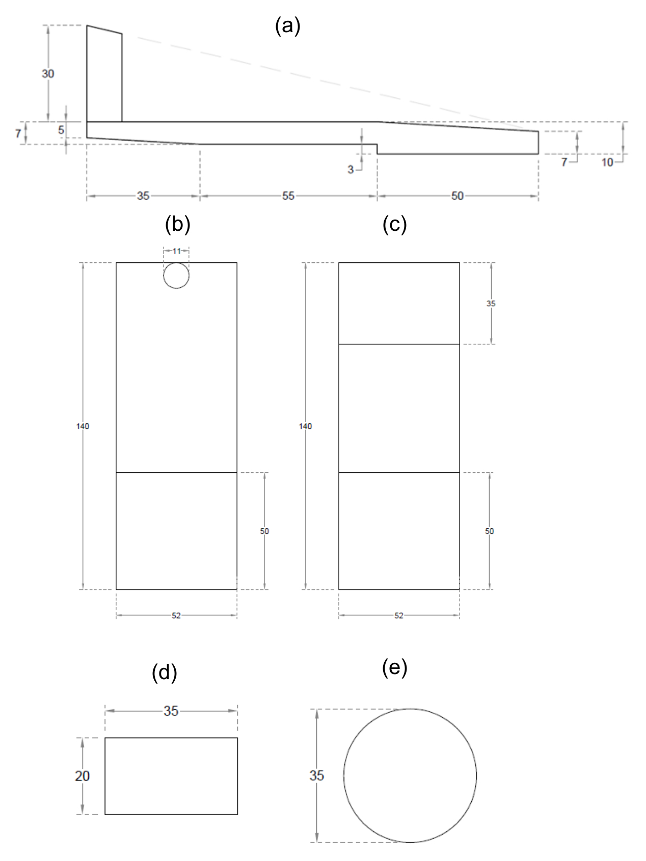
- After the tempering period, take one of the soil balls and flatten it by hand on the nonabsorbent smooth glass plate (use latex gloves to prevent loss of moisture) until the thickness is slightly higher than 3 mm. At this point, complete the flattening with the thread molder (Figure 2A,B,C) in order to obtain a thickness of exactly 3 mm.
Note: The thread molder is designed in such a way that there is a space of exactly 3 mm between the part which shapes the soil thread and the glass plate (Figure 2A).

Figure 2. Drawings and dimensions in mm of the thread molder and the steel pushers. (A) Side view, (B) top view, and (C) bottom view of the thread molder; (D) front view and (E) top view of the steel pushers. This figure has been modified from Moreno-Maroto & Alonso-Azcárate25. Please click here to view a larger version of this figure.
- Cut the jagged edges of the flattened soil mass with a spatula (the cut must be straight).
- Cut with a spatula a soil strip that is at least 52 mm long and a square section of approximately 3 × 3 mm.
- Shape a cylindrical soil thread of exactly 3 mm in diameter and 52 mm long.
- Roll and round the 3 × 3 mm section soil strip with the thread molder: move the thread molder successively backwards and forwards by hand until the exact moment at which the initially square section of the soil thread becomes round, so now it must be 3 mm in diameter.
- If the initial soil strip is difficult to roll with the thread molder (e.g., in low cohesive soils or even in plastic soils in water contents close to the PL), at the beginning, round the square section by hand very carefully (use gloves). Just after, roll the soil thread with the thread molder as described in the step 3.5.1 until an exactly 3mm in diameter soil thread is obtained.
- Place the soil thread and the front side of the thread molder close together. Use the width of the thread molder as a template and cut the tips of the soil thread with a metal spatula in order to obtain a soil cylinder of exactly 52 mm in length.
Note: The thread molder measures 52 mm wide as shown in Figure 2 B,C.
- Roll and round the 3 × 3 mm section soil strip with the thread molder: move the thread molder successively backwards and forwards by hand until the exact moment at which the initially square section of the soil thread becomes round, so now it must be 3 mm in diameter.
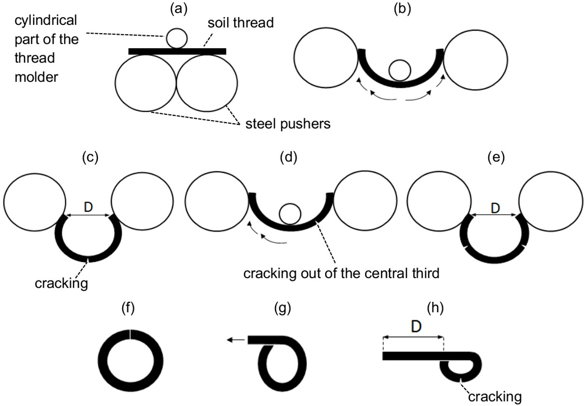
- Bend the soil thread until the point of cracking (Figure 3).
- Turn the thread molder upside down, so that now it is supported by its cylindrical piece and the device rear. Put the cylindrical piece of the thread molder in contact with the central part of the 3 mm in diameter × 52 mm long soil thread.
- Place the steel pushers (Figure 2D,E) in contact with the center of the soil thread (Figure 3A), so that the soil thread is located between the two steel pushers (these work as mobile supporting points) and the cylindrical part of the thread molder (this works as a fixed supporting point).
- Move carefully the steel pushers from the center to the tips of the soil thread (Figure 3B) in an approximately circular path. Repeat this motion until the point of cracking (Figure 3C); at this point, stop bending.
- If the crack appears out of the central third of the soil thread (Figure 3D), i.e., near one of the thread tips, keep bending around the other tip until another crack appears (Figure 3D,E). This way, two cracks are obtained along the soil thread.
- Right afterwards, remove the thread molder and measure the distance between the tips (D) of the thread with a caliper and record it to a precision of 0.1 mm. Take this measurement from the central part of the tips (Figure 3C,E).
- Put the soil thread into the container whose weight was previously recorded (step 3.1) and cover it to prevent moisture loss.
- If bending deformations are so large that even the thread tips come into contact, i.e., D=0 mm (Figure 3F), remove the pushers and thread molder and bend the soil thread by hand until the point of cracking as is shown schematically in Figure 3G. Measure the distance between the thread tips as shown in Figure 3H and record it with a negative sign. Finally, repeat step 3.6.4.1.

Figure 3. Schematic drawing where bending and tips distance measurement techniques are detailed. (A) Initial position of the steel pushers, the soil thread and the cylindrical part of the thread molder on the glass plate. (B) Usual bending technique by means of an approximately circular path from the center to the tips which is carried out very carefully (see the arrows path). (C) Usual tip distance measurement technique of a thread that has cracked in its central part. (D) Soil thread that has cracked out its central third and bending technique to be followed around the other tip (that indicated by the arrows). (E) Usual tip distance measurement technique of a thread that has cracked out of its central third. (F) Soil thread in which tips come into contact and can form a closed ring. (G) Bending technique to be conducted when the soil thread is able to bend beyond a closed ring and (H) tip distance measurement technique for this last case. This figure has been modified from Moreno-Maroto & Alonso-Azcárate25. Please click here to view a larger version of this figure.
- Shape other soil threads from the same flattened soil mass according to steps 3.4, 3.5.1, 3.5.1.1. Do not cut their tips. Finally, put them into the container and cover it (step 3.6.4.1).
Note: The role of these threads is simply to obtain enough material to correctly determine the moisture content. If the contact surfaces (the glass plate and the thread molder) were dirty after shaping a thread, clean them with a damp cloth and dry them with a piece of paper quickly. - Repeat steps 3.4 through 3.6.4.2 for at least another soil thread. Shape these threads with a certain alternation with respect to those obtained in the step 3.7. If the second measurement of tip distance (D) is the same or quite similar to that obtained in the first soil thread, do not bend more threads. If not, shape and bend at least one further soil thread.
Note: The term "a certain alternation" means that it is recommended that the bent threads are not shaped one after the other, i.e., they should not be taken from the same area of the flattened soil mass in order to obtain representative measurements of the whole soil mass. Thus, some of those soil threads that are not cut and bent (step 3.7) should be shaped between the bent ones. If there was an inhomogeneous moisture distribution in the flattened soil mass (which is unlikely), it would be corrected this way. - Weigh the container with the soil threads to a precision of at least 0.01 g. Shape and add more threads according to steps 3.4, 3.5.1, 3.5.1.1 if the weight of the soil threads is less than 5 g, until this weight is exceeded (a weight between 5 and 7 g is suitable).
- Repeat steps 3.1 through 3.9 for the other soil ball (the ball shaped in step 2.3).
- In the case of very low plasticity soils, omit step 3.10 if the plasticity of the soil is too low to carry out the test properly for two balls with different water content (so that only a soil ball would be tested).
4. Determine the Moisture Content (W) of the Soil
- Place the two containers (corresponding to the two soil balls tested) with their respective soil threads in an oven at 105 ± 5 °C for a minimum of 18 hr (if the step 3.10.1 is applied, there is only one container with soil to dry). After this period, leave the containers with the dry soil in a desiccator and when they are cool, record their weights to a precision of at least 0.01 g.
- Place the containers with the dry soil again into the oven at 105 ± 5 °C for a minimum of 6 hr. Then allow them to cool and record their weights again as indicated in the step 4.1. If the weight is constant, i.e., if this weight is essentially the same as the obtained in the step 4.1, the soil is completely dry, therefore use this data to calculate the moisture content (W) in the step 5.2.
- If the weight is different, repeat step 4.2 as many times as necessary until the weight of the container with the dry soil is constant.
5. Calculate the Bending at Cracking (B) and the Moisture Content (W)
- Calculate the bending at cracking (B) in mm as follows:
B=52.0-D
where 52.0 refers to the length in mm of the soil thread, and D is the average distance measured between the tips at the time of cracking in mm:
D=(D1+D2…+Dn)/n
where n is at least 2 (see step 3.8) - Calculate the moisture content (W) in percentage as follows:
W= (M1-M2)/(M2-M3)×100
where:
M1 is the weight of the container with the wet soil (see step 3.9)
M2 is the weight of the container with the dry soil (see step 4.2)
M3 is the weight of the container (see step 3.1)
6. Calculate the Plastic Limit (PL)
- Calculate the plastic limit of the first soil ball as follows:
PL1 = W × (B/2.135)-0.108
where 2.135 refers to the average B on the bending curve at which PL was obtained in 24 soils according to the original bending test, whereas -0.108 refers to the average bending slope (m) of the bending curve of these 24 soils (Table 1 and Figure 4). - Repeat step 6.1 for the second soil ball and obtain PL2.
- Calculate the PL as the average of PL1 and PL2
PL = (PL1 + PL2)/2
Note: If more than two experimental points had been obtained, the PL is also the average of the PL results, i.e., PL=(PL1+PL2…+PLn)/n. - Omit Steps 6.2 and 6.3 if only one experimental point has been obtained (see step 3.10.1), therefore in this case:
PL = PL1
Note: It is important to highlight that in the present study the PL calculated through the step 6 has been named PLnb in order to differentiate it from the PL results achieved with the original bending test and the standard thread rolling test, which have been named PLob and PLst respectively.
결과
The PL equation shown in the step 6.1 of the protocol was achieved through a statistical study of the 24 soils tested in a previous study of the authors25 (Table 1). The objective was to know the most probable bending slope (the term m in the bending curve equation, which appears in Figure 1A) and the average value of B on the bending curve at which PL was obtained according to the original bending test (the original test was conducted...
토론
The Atterberg plastic limit1 is a very important parameter in soils, mainly because it is widely used for geotechnical purposes10,11,12. The standard thread rolling test for PL determination has been widely criticized because it is highly dependent on the skill and judgment of the operator who is conducting the test and consequently new approaches to obtain the PL are claimed6,7,9,13,15-20, 23-25. However the simplicity, low cost and quick performance of the standard PL test give it an ad...
공개
The authors have nothing to disclose.
감사의 말
This research has been partially funded by a grant (Beca de Investigaciòn Ambiental) from the Servicio de Medio Ambiente de la Diputaciòn Provincial de Toledo (gran number 133/10) and the research project PEII-2014-025-P of the Junta de Comunidades de Castilla-La Mancha.
자료
| Name | Company | Catalog Number | Comments |
| Shovel | Any | NA | It is preferable a round point metal shovel so that it can penetrate easily in the soil. |
| Trowel | Any | NA | It should be easy to handle both in field and laboratory, so approximately 500 g of soil should be the maximum of soil that could pick up. |
| Polyethylene bags | Any | NA | The size of the bags depends on the collected soil volume. If we were interested in preserving the natural moisture, use sealing tape to close the bag. |
| Soil splitter | PROETISA | S0012 | It is not mandatory, because the quartering can be performed with the shovel, but in case of using it: it must be big enough to split several kg of sample in the cases of soils with large amounts of gravel or pebbles. |
| Oven | SELECTA | 2001254 | The oven must be able to maintain constant temperature and should have some sort of slot or outlet opening to facilitate the release of water vapor. |
| Lab trays | Any | NA | Metal trays are preferred over plastic because the first ones tolerate the oven temperatures better than the second ones. |
| Mortar and pestle | MECACISA | V112-02 | A ceramic mortar is valid. It is recommended to use a rubber covered pestle because if the pestle was of other different materials (like metal or a ceramic), it could break the sand particles. |
| 0.40 mm sieve (or 0.425 mm sieve) | FILTRA | 0,400 (or 0,425) | Make sure that the sieve mesh is in perfect conditions of use (it should not be neither broken or worn). |
| Brush | Any | NA | It is useful for passing the soil during the sieving. |
| Wash-bottle | Any | NA | It should have an approximate capacity of one litre and it should be easy to control the amount of water that it releases. |
| Distilled water | Any | NA | Distilled water can be purchased or obtained by filtering from tap water (in this last case, a filtering system is necessary). |
| Nonabsorbent smooth glass plate | Any | NA | The plate should have a minimum area of approximately 30 × 30 cm. |
| Metal spatula | Any | NA | The metal blade of the spatula must be flexible. Dry it with a paper after water-cleaning to prevent rusting. |
| Latex gloves | Any | NA | Latex, vinyl, nitrile or other impermeable materials are valid. They should be thin enough to sense the soil with the hands. |
| Cling film | Any | NA | Normal cling film is valid. |
| Airtight bags | Any | NA | Remove the air before closing them. |
| Thread molder | Any | NA | It is a tool designed in this experiment (drawings with dimmensions are included in this paper). |
| Steel pushers | Any | NA | It is a tool designed in this experiment (drawings with dimmensions are included in this paper). |
| Damp cloth | Any | NA | A normal damph cloth is valid. |
| Roll of paper | Any | NA | Normall rolls of paper used to dry hands are valid. |
| Caliper | Any | NA | It must have an accuracy of at least 0.1 mm. |
| Paper and pen | Any | NA | Paper and pen are used to write the results. |
| Containers with covers | Any | NA | Small cylindrical glass containers are valid. If they do not have covers, watch glasses can be used as covers. Covers are useful to avoid the loss of water during the test and also to prevent the dry soil absorbs moisture from the air after oven drying. |
| Precision or analytical balance | BOECO | BPS 52 PLUS | It must have an accuracy of at least 0.01 g. |
| Protective gloves | Any | NA | Protective gloves are used to catch the metal trays from the oven. |
| Tongs | Any | NA | Tongs are used to catch the hot containers from the oven. |
| Desiccator | MECACISA | A036-01 | A normal glass desiccator with silica gel is valid to prevent the dry soil absorbs moisture from the air after oven drying. |
참고문헌
- Atterberg, A. Über die physikalische Bodenuntersuchung und über die Plastizität der Tone. Internationale Mitteilungen für Bodenkunde. 1, 10-43 (1911).
- . . ASTM Standard ASTM D 4318. Standard Test Methods for Liquid Limit, Plastic Limit, and Plasticity Index of Soils. , (2005).
- . . UNE 103-103-94. Determinaciòn del lìmite lìquido de un suelo por el método del aparato de Casagrande. , (1994).
- . . BS 1377-2. Methods of test for soils for civil engineering purposes-Part 2: Classification tests. , (1990).
- . . UNE 103-104-93. Determinaciòn del lìmite plástico de un suelo. , (1993).
- Whyte, I. L. Soil plasticity and strength: a new approach using extrusion. Ground Eng. 15 (1), 16-24 (1982).
- Temyingyong, A., Chantawaragul, K., Sudasna-na-Ayudthya, P. Statistical Analysis of Influenced Factors Affecting the Plastic Limit of Soils. Kasetsart J. (Nat. Sci.). 36, 98-102 (2002).
- Bobrowski, L. J., Griekspoor, D. M. Determination of the Plastic Limit of a Soil by Means of a Rolling Device. Geotech. Test. J., GTJODJ. 15 (3), 284-287 (1992).
- Rashid, A. S. A., Kassim, K. A., Katimon, A., Noor, N. M. Determination of Plastic Limit of soil using modified methods. MJCE. 20 (2), 295-305 (2008).
- . . ASTM Standard ASTM D 248. Standard Practice for Classification of Soils for Engineering Purposes (Unified Soil Classification System). , (2000).
- Casagrande, A. Research on the Atterberg limits of soils. Public Roads. 13 (8), 121-136 (1932).
- Casagrande, A. Classification and Identification of Soils. Transactions, ASCE. 113, 901-991 (1948).
- Sokurov, V. V., Ermolaeva, N., Matroshilina, T. V. Plastic limit of clayey soils and its subjetive determination. Soil Mech. Found. Eng. 48 (2), 52-57 (2011).
- Andrade, F. A., Al-Qureshi, H. A., Hotza, D. Measuring the plasticity of clays: A review. Appl. Clay Sci. 51, 1-7 (2011).
- Harison, J. A. Using the BS cone penetrometer for the determination of the plastic limits of soils. Géotechnique. 38 (3), 433-438 (1988).
- Feng, T. W. Fall-cone penetration and water content relationship of clays. Géotechnique. 50 (2), 181-187 (2000).
- Feng, T. W. Using a small ring and a fall-cone to determinate the plastic limit. ASCE, J. Geotech. Geoenviron. Eng. 130 (6), 630-635 (2004).
- Lee, L. T., Freeman, R. B. Dual-weight fall cone method for simultaneous liquid and plastic determination. ASCE, J. Geotech. Geoenviron. Eng. 135 (1), 158-161 (2009).
- Sivakumar, V., Glynn, D., Cairns, P., Black, J. A. A new method of measuring plastic limit of fine materials. Géotechnique. 59 (10), 813-823 (2009).
- Sivakumar, V., O'Kelly, B. C., Henderson, L., Moorhead, C., Chow, S. H. Measuring the plastic limit of fine soils: an experimental study. P. I. Civil Eng. - Geotec. 168 (GE-1), 53-64 (2015).
- Wroth, C. P., Wood, D. M. The correlation of index properties with some basic engineering properties of soils. Can. Geotech. J. 15 (2), 137-145 (1978).
- Haigh, S. K., Vardanega, P. J., Bolton, M. D. The plastic limit of clays. Géotechnique. 63 (6), 435-440 (2013).
- Barnes, G. E. An apparatus for the plastic limit and workability of soils. P. I. Civil Eng. - Geotec. 162 (3), 175-185 (2009).
- Barnes, G. E. An apparatus for the determination of the workability and plastic limit of clays. Appl. Clay Sci. 80-81, 281-290 (2013).
- Moreno-Maroto, J. M., Alonso-Azcárate, J. An accurate, quick and simple method to determine the plastic limit and consistency changes in all types of clay and soil: The thread bending test. Appl. Clay Sci. 114, 497-508 (2015).
- Bain, J. A. A plasticity chart as an aid to the identification and assessment of industrial clays. Clay Miner. 9 (1), 1-17 (1971).
재인쇄 및 허가
JoVE'article의 텍스트 или 그림을 다시 사용하시려면 허가 살펴보기
허가 살펴보기This article has been published
Video Coming Soon
Copyright © 2025 MyJoVE Corporation. 판권 소유