
Aby wyświetlić tę treść, wymagana jest subskrypcja JoVE. Zaloguj się lub rozpocznij bezpłatny okres próbny.
Method Article
Glass-Based Devices to Generate Drops and Emulsions
W tym Artykule
Podsumowanie
Here, a protocol to manufacture glass-based microfluidic devices used for generating highly monodisperse emulsions with controlled drop size is presented.
Streszczenie
In this manuscript, three different step-by-step protocols to generate highly monodisperse emulsion drops using glass-based microfluidics are described. The first device is built for the generation of simple drops driven by gravity. The second device is designed to generate emulsion drops in a coflowing scheme. The third device is an extension of the coflowing device with the addition of a third liquid that acts as an electric ground, allowing the formation of electrified drops that subsequently discharge. In this setup, two of the three liquids have an appreciable electrical conductivity. The third liquid mediates between these two and is a dielectric. A voltage difference applied between the two conducting liquids creates an electric field that couples with hydrodynamic stresses of the coflowing liquids, affecting the jet and drop formation process. The addition of the electric field provides a path to generate smaller drops than in simple coflow devices and for generating particles and fibers with a wide range of sizes.
Wprowadzenie
Controlled generation of drops in the micron and nanoscale with a narrow size distribution is a challenging task. These drops are of interest for the engineering of soft materials with many applications in science and technology1,2,3,4,5,6.
The most common devices for the high production rate of drops are mixers7 and ultrasound emulsificators8. These methods are simple and low cost, but they typically result in polydisperse drops with a wide range of sizes. Hence, additional steps are required to produce monodisperse samples. Microfluidic devices can be designed differently to provide an efficient way to drop formation. Additionally, the usually low flow rates involved (i.e., low Reynolds number) allow for great control over the fluid flow.
While microfluidic devices are commonly made using lithographic techniques with poly(dimethyl) siloxane (PDMS), this manuscript focuses on glass-based capillary devices. PDMS devices are usually chosen for their ability to design complex channel patterns and because of their scalability. Glass devices, on the contrary, are rigid and have greater solvent resistance than their PDMS counterparts. Additionally, glass can be modified to change its wettability, which allows controlling the generation of complex emulsions. Being able to independently treat the nozzle and channel walls enables the formation of drops in a controlled and reproducible manner, while assuring the stability of the resultant emulsions if the drops were to touch the walls9; otherwise the drops may coalesce and accumulate at the wall. Another difference between these two types of devices is that in glass-based devices, the flow is three-dimensional, while it is planar in conventional PDMS devices. This fact minimizes the drop contact with the channel walls so that the influence of contact lines can be neglected10, thereby protecting the stability of multiple emulsion drops.

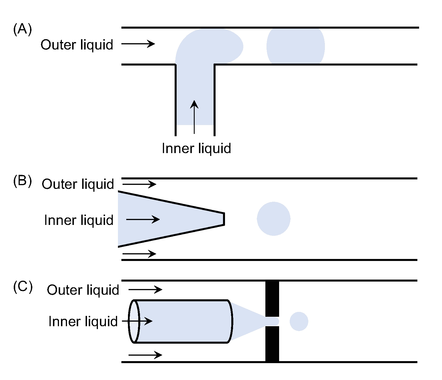
Figure 1: Different microfluidic device configurations. Sketches of (A) a T-junction, (B) a coflowing device, and (C) a flow-focusing device. Please click here to view a larger version of this figure.
There are three main geometries used, namely T-junction11, flow focusing12,13, and coflow14. In the T-junction geometry, the dispersed phase contained in the channel perpendicularly intersects the main channel which houses the continuous phase. The shear stress exerted by the continuous phase breaks the incoming dispersed liquid resulting in drops. The generated drops are limited in lower size by the dimensions of the main channel11. In the flow-focusing geometry, the two fluids are forced through a small orifice that is located in front of the injection tube. The result is the formation of a jet, which is much smaller than the injection tube12,13. Finally, the coflow geometry has a configuration characterized by the coaxial flow of two immiscible fluids14. In general, dripping and jetting can be observed depending on the operating conditions. The dripping regime occurs at low flow rates and the resulting droplets are very monodisperse and have a diameter proportional to the tip size. The drawback is its low production frequency. The jetting regime occurs at higher flow rates as compared to the dripping regime. In this case, the drop diameter is directly proportional to the diameter of the jet which can be much smaller than the diameter of the tip under the right conditions.
An alternative to these hydrodynamic approaches relies on the additional use of electric forces. Electrospray is a well-known and widely used technique for generating droplets. It is based on the principle that a liquid with a finite electrical conductivity will deform in the presence of a strong electric field. The liquid will eventually adopt a conical shape resulting from the balance between electric and surface tension stresses15. The process starts with the electric field inducing an electric current in the liquid that causes charges to accumulate at the surface. The presence of the electric field results in an electric force on these charges, which drags the liquid along, elongating the meniscus in the direction of the field. Under different conditions, the meniscus can either shed the charged drops or may emit one or several jets which then break into drops15. Although these electrically assisted microfluidic methods naturally allow the generation of small drops, they suffer from a lack of a steady-state operation that compromises the emulsion monodispersity. The resultant charged drops tend to discharge on the confining walls and/or anywhere in the device where the electric potential is lower than the imposed external voltage. Thus, the electrified meniscus becomes unstable, ultimately emitting drops in a chaotic way and causing their uncontrolled production and loss of monodispersity.
In electro-coflow, the electrical and hydrodynamic stresses are coupled in a coflow microfluidic device16 similar to the one used for generating double emulsions12. Two main features allow electro-coflow to be successful in reaching a steady-state emission regime: (i) the dispersed phase is ejected into another coflowing viscous liquid, and (ii) the use of a liquid counter-electrode or ground. Having a flowing outer liquid has proven to change the geometric properties of the drop emission process17. The liquid counter-electrode allows the discharge and extraction of the resultant drops, assuring the steady-state generation of drops. In addition, by exploiting the balance of electrical and hydrodynamic forces, the resultant drop sizes can potentially vary within a wider range than the sizes that can be covered by any of the previously mentioned techniques.
This detailed video protocol is intended to help new practitioners in the use and fabrication of glass-based microfluidics.
Protokół
1. Making simple drops
- For making simple drops, use a glass base made with a microscope slide (76.2 mm x 25.4 mm) to build the device. This allows for easy transportation and visualization of the liquids through the glass.
- Use a round glass capillary for the tip. For this protocol, use 1 mm diameter round capillaries (readily available in a wide range of sizes).
- To make a tip with the desired diameter, pull the capillary using a micropipette pulling machine until two half capillaries with a very small tip (~ 1 µm) are obtained.
- Use a microforge to cut the tip to the desired diameter (2-80 µm). For larger diameters (> 80 µm), use a ceramic tile if the microforge does not cut those sizes.
NOTE: Depending on the desired liquid, the glass will need to be treated, so that the liquid does not climb along the outside of the tip.
- For water-based liquids, make the exterior of the tip hydrophobic. For oil-based liquids, when the exterior of the tip is in contact with water, make the exterior of the tip hydrophilic. See step 2.3 for glass treatment.
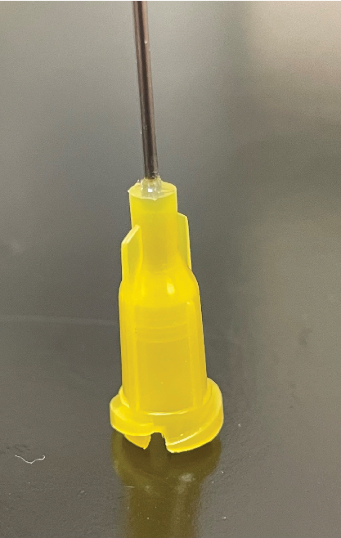
- Use a syringe needle (20 G) to facilitate introducing the liquid into the capillary. Carve a hole - of the size of the outer diameter of the capillary - at the base of the needle using a razor blade or a scalpel.
- Rinse the needle with water to remove any dust and fibers from cutting. Air-dry them.
- To assemble, glue the round capillary to the microscope slide using quick dry epoxy. Place the tip of the capillary 1-2 cm outside the end of the microscope slide. Use just a dab of epoxy at the center of the capillary. In this way, it will not interfere with the field of vision or with the syringe needle.
- Glue the syringe needle in such a way that the end of the capillary sits at the center of the needle. First, put a small amount of almost hardened epoxy around the rim at the bottom of the needle. Place the needle such that the end of the capillary is at the center of its base.
- After a few minutes, put a second layer of fresh epoxy, covering the base of the needle, avoiding the hole. Finally, cover the hole with almost hardened epoxy to prevent the epoxy from flowing inside the needles. Follow epoxy manufacturer's guidelines for hardening and curing times.
- Attach a piece of tubing (I.D. x O.D. 0.86 mm x 1.32 mm) to the needle. Clean the tube before you attach it. Flush deionized water manually using a syringe to remove any residues produced when the tubing was cut.
NOTE: The tubing material should be compatible with the liquid being used in the experiments. The tubing should be long enough to be able to connect the device and the pumping system. - For testing the device, pump deionized water through the needle and observe if there are any leaks. Use a syringe and its corresponding needle to manually pump the water. In case a leak is found, thoroughly dry the device. Apply epoxy and wait for at least 1 h before testing again.
- For generating drops, using a clamp, place the device in a vertical position so the tip is facing down like in a kitchen faucet. Use a syringe pump or a pressure-driven setup to pump the liquid into the device.
- Collect drops by placing the tip inside a beaker or a vial with a liquid with the appropriate amount of surfactant. For example, for 10cSt silicone oil as inner liquid, use a continuous phase of 16 mM sodium dodecyl sulfate (SDS) in water.
- For oil drops in water, in order to increase the stability of the drops, add a layer of viscous oil on top of the collection bath before making the emulsion. For water drops in oil, use a non-ionic surfactant in the oil to stabilize the drops.

Figure 2: Carved needle. Needle with a hole carved in its base to fit a round capillary. Please click here to view a larger version of this figure.

Figure 3: Device for generating simple drops. Schematic of a device for generating simple drops. Please click here to view a larger version of this figure.

Figure 4: Collecting simple drops. (A) Sketch of how to collect drops in a beaker. (B) Top view of a beaker where 10cSt silicone oil drops were collected in 16 mM SDS in water solution, produced with a 580 µm tip. The drop size is (3.29 ± 0.08) mm. (C) Top view of a beaker where 10cSt Silicone oil drops were collected in 16 mM SDS in water solution , produced with an 86 µm tip. The drop size is (1.75 ± 0.04) mm Please click here to view a larger version of this figure.
2. Making emulsion drops using a coflowing scheme
NOTE: The device is built similar to the device described in step 1.
- Build the device on a glass base made with a microscope slide (76.2 mm x 25.4 mm). This allows for easy transportation and visualization of the liquids through the glass.
- Use a capillary with square section (square capillary) for the outer liquid (continuous phase of the emulsion) with a length of about 5 cm. For this protocol, use 1 mm diameter round capillaries (readily available in a wide range of sizes).
- For glass treatment, depending on the chosen inner liquid (dispersed phase), make the inner side of the square capillary hydrophobic or hydrophilic. The treatment will help avoid having drops stuck in the glass and interfering with the formation of new drops.
- For making glass hydrophobic, clean the capillaries by putting them into a vial with acetone in the ultrasound bath for 10-15 min. Rinse them with acetone or ethanol (never water). Dry them.
- Prepare a clean and dry (bone dry) vial containing a 10 mL toluene (or hexane) + 20 µL of trimethoxy(octyl)silane solution. Keep the capillaries in the solution for 2 h. Rinse the capillaries with the same solvent used for the solution.
- Rinse again with acetone. Dry with air. Bake them in the oven for 30 min at about 70 °C.
NOTE: This process is difficult to implement for the device tips without breaking them. - To treat the device tips, dip them in the solution of toluene and trimethoxy(octyl)silane solution for a few seconds. Remove any excess solution. Allow to air dry.
- For making glass hydrophilic, repeat the same steps (2.3.1-2.3.4) as in the hydrophobic case but with a solution of 10 mL of acetone + 20 µL of 2-[methoxy(polyethyleneoxy)6-9propyl] trimethoxysilane.
- Use a round glass capillary for the tip. Match the outer diameter of the capillary to the inner size of the square capillary. This ensures both capillaries are coaxially aligned. Ensure that the length of the round capillary is several centimeters longer than the square capillary.
- Depending on the dispersed liquid, treat the glass, so the liquid does not climb along the outside of the tip.
- Assemble by gluing the square capillary to the microscope slide using quick dry epoxy. Place the tip of the capillary 1-2 cm outside the end of the microscope slide (see Figure 6A).
- Use a dab of epoxy at the center of the capillary, so that it does not interfere in the field of view or with the syringe needle. Wait until it cures completely. Note that even for quick dry epoxy, the manufacturer recommends 24 h for the material to completely cure.
- Introduce the round capillary into the square one such that the end stays a few centimeters outside the end of the square capillary.
- Place the other end (outside of the microscope slide) inside the square capillary at a distance that approximately coincides with the end of the square capillary (see Figure 6B).
- Glue the capillary using a dab of epoxy at mid-distance between the end of the capillary and the beginning of the square one. Wait until it cures completely.
- Make the following modifications in the two needles required to introduce the liquid.
- To house the capillary in the base of the needle, carve a hole in the base of the round cap which is of the size of the outer diameter of the capillary (see Figure 2). To fit the other needle at the end of the square capillary, carve round and square holes at the base of the needle to accommodate the joint.
- Ensure that both holes are aligned so that the round and square capillaries can be fitted inside the needle. Rinse the needles with water to remove any dust and fibers from cutting. Air-dry them. Glue the needles and follow the protocol already described in 1.5.2 (see Figure 6C).
- Connect the tubing (check diameter and compatible material) to each of the needles. Rinse the tubing after cutting them so any debris and fibers are removed. Manually, use a syringe and a needle to pump the water. Test the device for leaks as described below.
- Close one of the needles by bending a piece of tubing and using a binder clip to effectively close it from fluid flow. Pump deionized water through the other needle. If no leaks are observed, pump through the other needle.
- If a leak is found, thoroughly dry the device, apply epoxy, and wait for at least 1 h before testing again.
- For generating drops, as described in step 1.8, use one of the two ways to drive the liquids: fixing their flow rates using syringe pumps, or fixing their pressure using pressurized canisters.

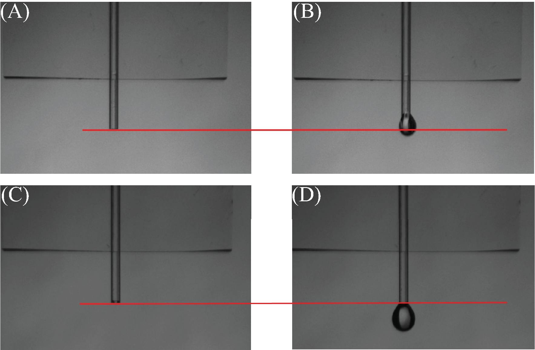
Figure 5: Effects of the hydrophobic treatment. (A) and (C) Capillary without any liquid inside. The red line indicates the end of the capillary. (B) Untreated capillary. The liquid is wetting the capillary as it has climbed above the red line. (D) Treated capillary with water. Water does not wet the capillary in this case. Liquid stays below the red line. Please click here to view a larger version of this figure.

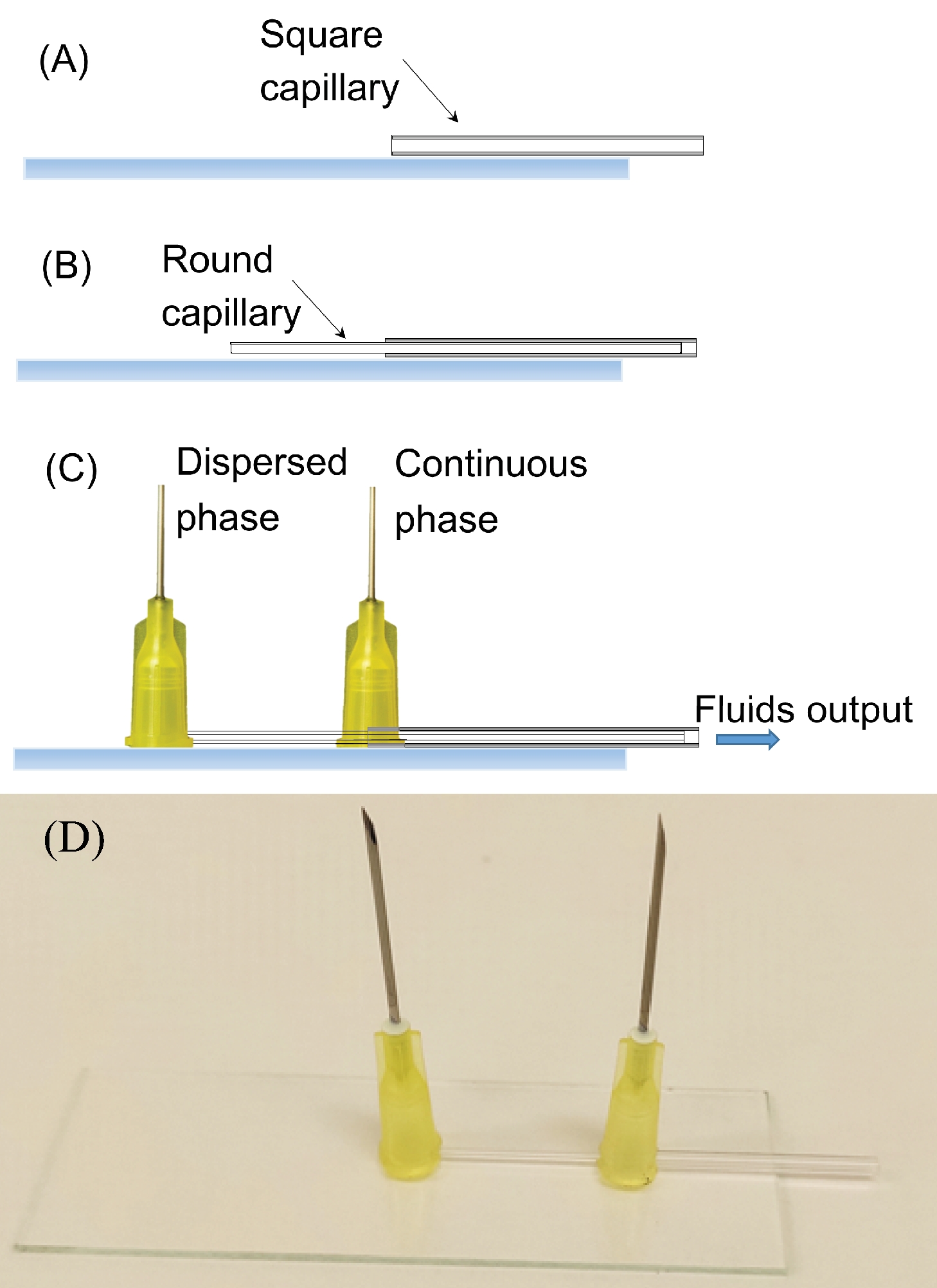
Figure 6: Coflowing device. (A) Position the square capillary on the microscope slide. (B) Position the round capillary inside the square one. (C) The complete device with the syringe needles. (D) Photograph of the complete device. Please click here to view a larger version of this figure.
3. Making an electro-coflow device
- To build the microfluidic device use a glass base made with microscope slides (76.2 mm x 25.4 mm). Owing to their length, too long to fit on a single standard microscope slide, use 1 ½ or two microscope slides.
- Cut two small pieces of a slide (about 1 cm) to keep the slides together as shown in Figure 7A. Use epoxy to glue the glass. Wait until it cures.
- Align two capillaries coaxially. To avoid the extra cost of aligning two round capillaries of different diameters, use a square capillary with an inner side that matches the outer diameter of the round capillary. For electro-coflow experiments, use a 2 mm side capillary.
NOTE: The 2 mm side capillary makes the electro-coflow experiments work better as the tip-ground distance is smaller (or similar) than the distance between the tip and the wall of the square capillary. When using the 1 mm side capillary, the capillary wall is closer than the ground and the liquid often tends to discharge there, leading to non-reproducible results.- Use a diamond scribe or other available tool to cut the square capillary to a length of about 4 cm. Rinse it with water to remove any glass particles. Allow to air dry. Make it hydrophobic if the dispersed phase is a water-based liquid, otherwise, hydrophilic.
- Pull a round capillary with a pipette pulling machine until you obtain two half capillaries with a small tip.
- Use a microforge to cut the tip of one of the half capillaries to the desired diameter (20-80 µm). For larger diameters, you may use a ceramic tile. For water in oil emulsions, make the outside of the tip hydrophobic.
- Use the other half capillary as a collector capillary. To do so, cut the pulled tip so the original flat ends are recovered.
- Cut the two round capillaries to be around 4-5 cm long (keep them shorter than the slide). Clean them to remove any residue generated during the cutting process. Flush them with deionized water using a syringe. Air dry them.
- Glue the square capillary to the slides (see Figure 7B). Do not center it relative to the slides; the joint of the slides should not be in the viewing region. Put a dab (to prevent spreading) of almost cured epoxy on the ends.
- Place the tip and the collector capillaries inside the square capillary. Place both ends - tip and one end of the collector - on the same slide, to avoid the joint between slides (see Figure 7C). The distance between the tip and the collector is around 2 mm. Use a microscope to measure this distance.
NOTE: This distance will depend on the technique you are using to pump the liquids. The final goal is to have a distance of about 1 mm between the tip and the liquid counter-electrode. - Once the capillaries are at the right distance, glue them to the slide using a dab of epoxy. Be careful not to cover the region of interest with epoxy, as it would make the visualization in the microscope difficult.
- To fabricate connections to the open ends of the capillaries, position needles covering these ends. Four needles per device are required.
- Use a razor blade or a scalpel to cut the base of the needles so that they fit over the capillaries. Make a round hole at the base of the needle to fit a needle at the end of the round capillaries.
- To fit it at the end of the square capillary, make round and square holes at the base of the needle to accommodate this joint. Be sure both holes are aligned so that round and square capillaries can be fitted inside the needle.
- Rinse the needles with water to remove any dust and fibers from cutting. Air dry them.
- Glue the needles. Follow the steps in 1.5.2. Allow the epoxy to cure overnight before testing the device for leaks.
- To test the device for leaks, follow the steps outlined below.
- Close two of the needles by using a bent piece of tubing held by a binder clip. Pump deionized water through one of the needles and use the last one as an exit. Use a syringe and its corresponding needle to manually pump water into the device.
- If no leaks are observed, pump through the next needle. Repeat the process until the water is through all four needles. In case a leak is found, thoroughly dry the device, apply epoxy, and wait for at least 1 h before testing again.
- Fill the device as described below and remove air bubbles as they may introduce undesirable oscillations in the system. To remove bubbles, use two half-filled syringes with deionized water. Push and pull the syringes to guide the air trapped inside the needles and capillaries out of the device.
- Prepare syringes with the liquids to be used in the experiment. Remove any bubbles from the syringes as described above. Connect a piece of tubing to the syringe needle and fill it with the liquid removing all the air.
- To connect the tubing to the device, remove the tubing used for testing from one of the device needles and pump water using one of the connected water syringes, so that the needle is dripping water.
- At the same time, make the tubing drip with the desired liquid. Because both ends are dripping, when connected, no air is introduced. Repeat this process with the other two syringes, so the only free needle in the device is the exit.
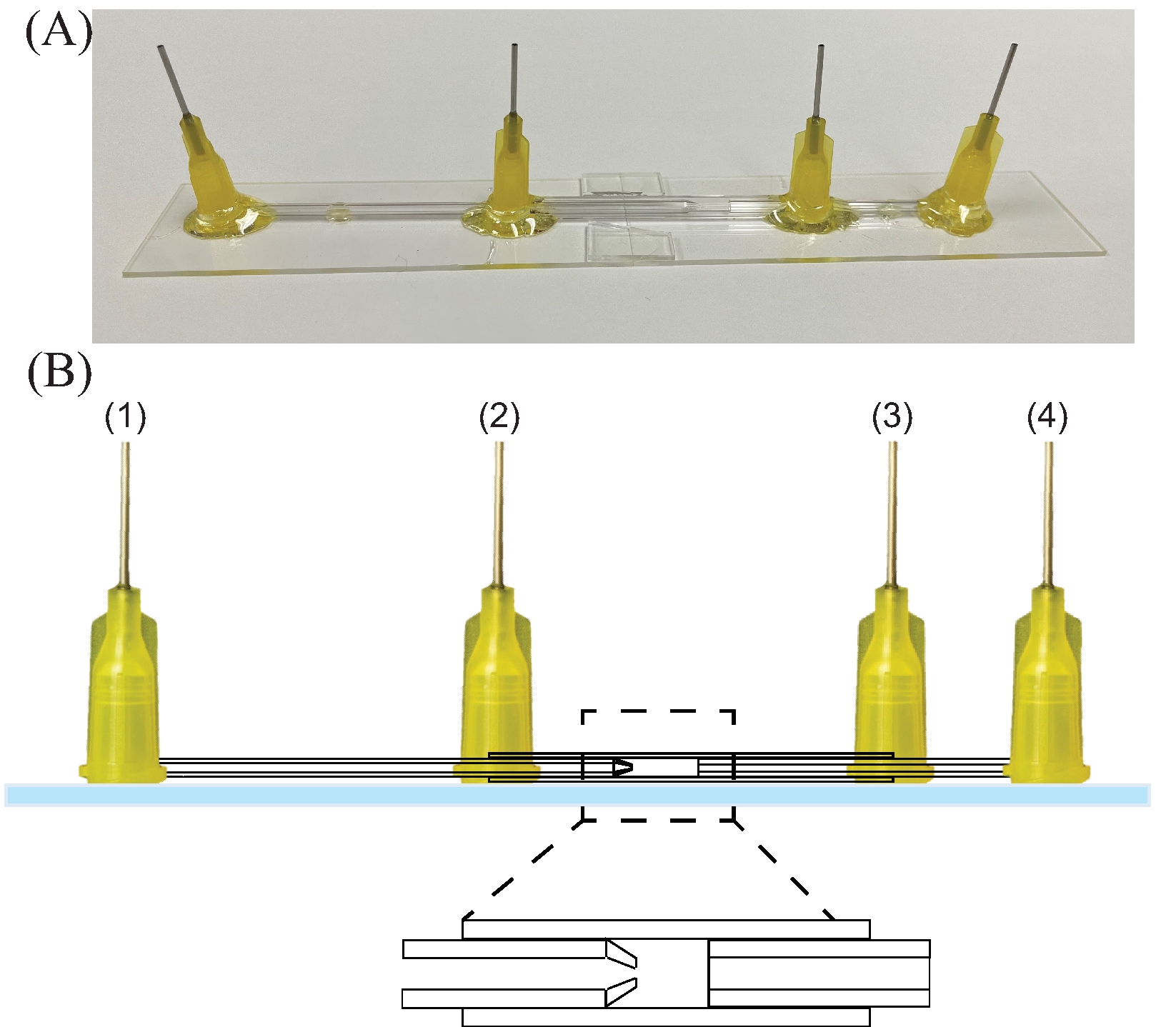
- Connect the inner liquid (dispersed phase) syringe to needle 1, the outer liquid (continuous phase) to needle 2, and the collector liquid (counter-electrode) to needle 4. Needle 3 is the exit (see Figure 8).
- Connect the power supply to the needles feeding the inner and collector liquids (needles 1 and 4 in Figure 8) to set a potential difference between the tip and collector liquid.
NOTE: Because the needle is metallic, and in contact with these conducting liquids, they act as liquid wires setting the potential difference between the tip and the collector meniscus. For the mentioned device dimensions, the potential difference will range between 0 and 2.5 kV. - Pump the liquids using one of the two possible ways, depending on the laboratory equipment: use high-pressure syringe pumps that will fix the flow rate of the liquids or use pressure canisters that will fix the pressure of the liquids.
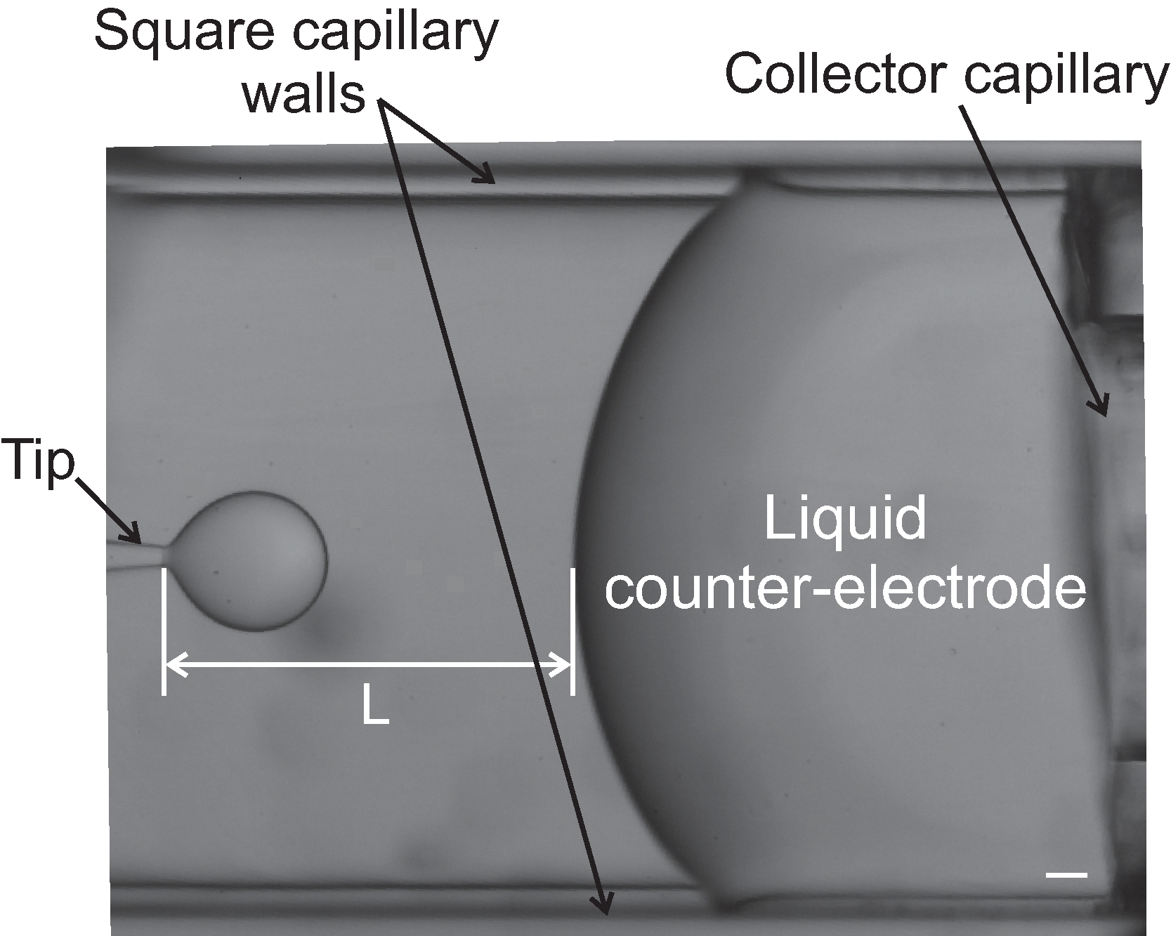
- Once one of these methods is chosen, fix the outer and inner flow rates to the desired values and adjust the flow rate (or pressure) of the liquid collector to keep the distance, L, constant (see Figure 9).

Figure 7: How to position the capillaries on an electro-coflow device step by step. (A) Building the glass base for the device joining two microscope slides. The colored parts are the cut pieces of glass that after being glued, hold together the two microscope slides. (B) The optimal position of the square capillary on two assembled microscope slides. (C) Positioning of the round capillaries for electro-coflow experiments. Please click here to view a larger version of this figure.

Figure 8: Electro-coflow device. (A) Photograph of an electro-coflow device. (B) Sketch of an electro-coflow device. The numbers indicate the input for (1) the inner liquid, (2) the outer liquid, (3) the exit of the device, and (4) the liquid collector/ground. Please click here to view a larger version of this figure.

Figure 9: Picture of the tip and liquid counter-electrode during an electro-coflow experiment. The tip-collector distance, L, is marked. The scale bar corresponds to 100 µm. Microscope magnification is 4x. Please click here to view a larger version of this figure.
4. Cleaning procedures
- Keep the capillaries and microscope slides in acetone to remove all dust and oil. Any oil particle or dust could clog the micron-size tips. Check the tips for clogs after each step during the fabrication with a 4x to 20x magnification microscope for tip sizes between 10 to 100 µm.
- Pump deionized water through the tubing before use. Use a syringe and a needle and manually pump the water to prevent any undesirable particle from traveling from inside of the tube into the device and clogging the tip.
Wyniki
In this manuscript, three different devices have been designed to generate drops. We have generated drops with a size of (3.29 ± 0.08) mm (Figure 4B) and (1.75 ± 0.04) mm (Figure 4C) using the device described in step 1. The emulsion drops can be generated using the coflow and the electro-coflow devices. For the latter, we show dripping in Figure 9, while cone-jet and whipping modes are shown in
Dyskusje
The protocol to fabricate three different glass-based devices has been described above. In the case of the device to generate simple drops, the flow rate and liquid properties are crucial to generate drops in a controlled manner. Drops will form at the tip in the dripping regime, or at the end of the jet in the jetting regime. The transition from dripping to jetting is parametrized by the dimensionless Weber number, We23. This number represents the ratio between inertial and surface tension forces...
Ujawnienia
The authors have nothing to disclose.
Podziękowania
We are thankful to the ACS PRF (grant 60302-UR9), Agrobio S.L. (contract #311325), and MCIN/AEI/10.13039/501100011033/FEDER, UE (grant No. PID2021-122369NB-I00).
Materiały
| Name | Company | Catalog Number | Comments |
| 2-[methoxy(polyethyleneoxy)6-9propyl] trimethoxysilane. | Gelest | SIM6492.7 | |
| Ceramic tile | Sutter | CTS | |
| Ethylene glycol | Fisher | BP230 | These can be found at other companies like Sigma-Aldrich |
| Hexane | Sigma- Aldrich | 34859 | Available in other vendors |
| ITW Polymers Adhesives Devcon 5 Minute Epoxy Adhesive 25 mL Dev-Tube | Ellsworth adhesives | 470740 | |
| Microforge | Narishige | MF 830 | |
| Micropipette puller | Sutter | P97 | |
| Microscope slides | Fisher | 12-544-1 | Available in other vendors |
| Needle 20 Gauge, .0255" ID, .0355" OD, 1/2" Long | McMaster | 75165A677 | |
| SDS | Sigma-aldrich | 428015 | Surfactant |
| Silicone oil | Clearco | PSF-10cSt | The catalog number correspond to the 10cSt viscosity oil. Different viscosity oils can be found at this company |
| Span 80 | Fisher | S0060500G | non-ionic surfactant |
| Square glass capillary 2mm ID (borosillicate 300 or 600 mm long) | VitroCom | S 102 | |
| Standard Glass Capillaries, 6 in., 2 / 1.12 OD/ID | World Precision instruments | 1B200-6 | These can be found at other companies like Sutter or Vitrocom |
| Syringe pump | Chemyx | FUSION 100-X | This model has a good quality/price ratio |
| Syringes (it will depend on the compatibility with the liquids) | Fisher | Catalog number will depend on the size | |
| Trimethoxy(octyl)silane | Sigma- Aldrich | 376221 | Available in other vendors |
| Tubing ( it will depend on the compatibility with the liquids) | Scientific commodities | BB3165-PE/5 | This reference is for polyethylene micro tubing. The size fits the needle size listed here |
Odniesienia
- Basaran, O. A. Small-scale free surface flows with break-up: drop formation and emerging applications. American Institute of Chemical Engineers. 48 (9), 1842-1848 (2004).
- Squires, T. M., Quake, S. R. Microfluidics: Fluid physics at the nanoliter scale. Reviews of Modern Physics. 77 (3), 977-1026 (2005).
- Stone, H. A., Stroock, A. D., Adjari, A. Engineering Flows in Small Devices: Microfluidics Toward a Lab-on-a-Chip. Annual Review of Fluid Mechanics. 36 (1), 381-411 (2004).
- Gunther, A., Jensen, K. F. Multiphase microfluidics: from flow characteristics to chemical and materials synthesis. Lab on a Chip. 6, 1487-1503 (2006).
- Barrero, A., Loscertales, I. G. Micro- and Nanoparticles via Capillary Flows. Annual Review of Fluid Mechanics. 39, 89-106 (2007).
- Clift, R., Grace, J. R., Weber, M. E. . Bubbles, Drops, and Particles. , (2005).
- Othmer, K. . Encyclopedia of Chemical Technology. 4th edition. 9, (1994).
- Kentish, S., et al. The use of ultrasonics for nanoemulsion preparation. Innovative Food Science & Emerging Technologies. 9 (2), 170-175 (2008).
- Kumar, A., Li, S., Cheng, C. M., Lee, D. Flow-induced phase inversion of emulsions in tapered microchannels. Lab on a Chip. 16 (21), 4173-4180 (2016).
- Atencia, J., Beebe, D. J. Controlled microfluidic interfaces. Nature. 437, 648-655 (2005).
- Garstecki, P., Fuerstman, M. J., Stone, H. A., Whitesides, G. M. Formation of droplets and bubbles in a microfluidic T-junctions scaling and mechanism of break-up. Lab on a Chip. 6 (3), 437-446 (2006).
- Utada, A. S., et al. Monodisperse Double Emulsions Generated from a Microcapillary Device. Science. 308 (5721), 537-541 (2005).
- Gañan-Calvo, A. M. Generation of Steady Liquid Microthreads and Micron-Sized Monodisperse Sprays in Gas Streams. Physical Review Letters. 80 (2), 285-288 (1998).
- Shah, R. K., et al. Designer emulsions using microfluidics. Materials Today. 11 (4), 18-27 (2008).
- Taylor, G. I. Disintegration of water drops in an electric field. Proceedings of the Royal Society A, Mathematical, Physical and Engineering Sciences. 280 (1382), (1964).
- Gundabala, V. R., Vilanova, N., Fernández-Nieves, A. Current-voltage characteristic of electrospray processes in microfluidics. Physical Review Letters. 105 (15), 154503 (2010).
- Guerrero, J., Rivero, J., Gundabala, V. R., Perez-Saborid, M., Fernández-Nieves, A. Whipping of electrified liquid jets. Proceedings of the National Academy of Sciences of the United States of America. 111 (38), 13763-13767 (2014).
- Vilanova, N., Gundabala, V. R., Fernandez-Nieves, A. Drop size control in electro-coflow. Applied Physics Letters. 99 (2), 021910 (2011).
- Cloupeau, M., Prunet-Foch, B. Electrostatic spraying of liquids: Main functioning modes. Journal of Electrostatics. 25 (2), 165-184 (1990).
- Jaworek, A., Krupa, A. Main modes of electrohydrodynamic spraying of liquids. Third International Conference on Multiphase Flow ICMF. , (1998).
- Juraschek, R., Röllgen, F. W. Pulsation phenomena during electrospray ionization. International Journal of Mass Spectrometry. 177 (1), 1-15 (1998).
- Guerrero, J., et al. Emission modes in electro co-flow. Physics of Fluids. 31 (8), 082009 (2019).
- Utada, A. S., Fernández-Nieves, A., Stone, H. A., Weitz, D. A. Dripping to jetting transitions in coflowing liquid streams. Physical Review Letters. 99 (9), 094502 (2007).
- Castro-Hernández, E., Gundabala, V., Fernández-Nieves, A., Gordillo, J. M. Scaling the drop size in coflow experiments. New Journal of Physics. 11, 075021 (2009).
- Godfray, H. C. J., et al. Food Security: the challenge of feeding 9 billion people. Science. 327 (5967), 812-818 (2010).
- Labbé, R., Gagnier, D., Kostic, A., Shipp, L. The function of supplemental foods for improved crop establishment of generalist predators Orius insidiosus and Dicyphus hesperus. Scientific Reports. 8 (1), 17790 (2018).
- Pilkington, L. J., Messelink, G., van Lenteren, J. C., Le Mottee, K. 34;Protected Biological Control" - Biological pest management in the greenhouse industry. Biological Control. 52 (3), 216-220 (2010).
- Benson, C. M., Labbe, R. M. Exploring the Role of Supplemental Foods for Improved Greenhouse Biological Control. Annals of the Entomological Society of America. 114 (3), 302-321 (2021).
- Temiz, U., Öztürk, E. Encapsulation methods and use in animal nutrition. Selcuk Journal of Agricultural and Food Sciences. 32 (3), 624-631 (2018).
- Messelink, G. J., et al. Approaches to conserving natural enemy populations in greenhouse crops: current methods and future prospects. BioControl. 59, 377-393 (2014).
- Muñoz-Cárdenas, K., et al. Generalist red velvet mite predator (Balaustium sp.) performs better on a mixed diet. Experimental & Applied Acarology. 62 (1), 19-32 (2014).
- van Lenteren, J. C., Bolckmans, K., Köhl, J., Ravensberg, W. J., Urbaneja, A. Biological control using invertebrates and microorganisms: plenty of new opportunities. BioControl. 63, 39-59 (2018).
- Urbaneja-Bernat, P., Alonso, M., Tena, A., Bolckmans, K., Urbaneja, A. Sugar as nutritional supplement for the zoophytophagous predator Nesidiocoris tenuis. BioControl. 58 (1), 57-64 (2013).
- Vila, E., Cabello, T., Guevara-Gonzalez, R., Torres-Pacheco, I. Biosystems Engineering Applied to Greenhouse Pest Control. Biosystems Engineering: Biofactories for Food Production in the Century XXI. , (2014).
- Riudavets, J., Moerman, E., Vila, E., LodovicaGullino, M., Albajes, R. C., Nicot, P. Implementation of Integrated Pest and Disease Management in Greenhouses: From Research to the Consumer. Integrated Pest and Disease Management in Greenhouse Crops. Plant Pathology in the 21st Century. , (2020).
- Cohen, A. C. . Insect diets: Science and technology. Second edition. , (2015).
- Sullivan, M. T., Stone, H. A. The role of feedback in microfluidic flow-focusing devices. Philosophical Transactions of the Royal Society A: Mathematical, Physical, and Engineering Sciences. 366 (1873), 2131-2143 (2008).
- Shang, L., Cheng, Y., Zhao, Y. Emerging droplet microfluidics. Chemical Reviews. 117 (12), 7964-8040 (2017).
- Christopher, G. F., Anna, S. L. Microfluidic methods for generating continuous droplet streams. Journal of Physics D: Applied Physics. 40 (19), 319 (2007).
- Nunes, J. K., Tsai, S. S., Wan, J., Stone, H. A. Dripping and jetting in microfluidic multiphase flows applied to particle and fiber synthesis. Journal of Physics D: Applied Physics. 46 (11), 114002 (2013).
Przedruki i uprawnienia
Zapytaj o uprawnienia na użycie tekstu lub obrazów z tego artykułu JoVE
Zapytaj o uprawnieniaThis article has been published
Video Coming Soon
Copyright © 2025 MyJoVE Corporation. Wszelkie prawa zastrzeżone