
A subscription to JoVE is required to view this content. Sign in or start your free trial.
Method Article
Low-Cost Electroencephalographic Recording System Combined with a Millimeter-Sized Coil to Transcranially Stimulate the Mouse Brain In Vivo
In This Article
Summary
A low-cost electroencephalographic recording system combined with a millimeter-sized coil is proposed to drive transcranial magnetic stimulation of the mouse brain in vivo. Using conventional screw electrodes with a custom-made, flexible, multielectrode array substrate, multi-site recording can be carried out from the mouse brain in response to transcranial magnetic stimulation.
Abstract
A low-cost electroencephalographic (EEG) recording system is proposed here to drive transcranial magnetic stimulation (TMS) of the mouse brain in vivo, utilizing a millimeter-sized coil. Using conventional screw electrodes combined with a custom-made, flexible, multielectrode array substrate, multi-site recording can be carried out from the mouse brain. In addition, we explain how a millimeter-sized coil is produced using low-cost equipment usually found in laboratories. Practical procedures for fabricating the flexible multielectrode array substrate and the surgical implantation technique for screw electrodes are also presented, which are necessary to produce low-noise EEG signals. Although the methodology is useful for recording from the brain of any small animal, the present report focuses on electrode implementation in an anesthetized mouse skull. Furthermore, this method can be easily extended to an awake small animal that is connected with tethered cables via a common adapter and fixed with a TMS device to the head during recording.The present version of the EEG-TMS system, which can include a maximum of 32 EEG channels (a device with 16 channels is presented as an example with fewer channels) and one TMS channel device, is described. Additionally, typical results obtained by the application of the EEG-TMS system to anesthetized mice are briefly reported.
Introduction
Transcranial magnetic stimulation (TMS) is a promising tool for human brain science, clinical application, and animal model research because of its non-/low invasiveness. During the early stage of TMS applications, measurement of the cortical effect in response to single- and paired-pulse TMS in humans and animals was restricted to the motor cortex; easily measurable output was limited to motor evoked potentials and induced myoelectric potentials involving the motor cortex1,2. To expand the brain regions that can be measured by TMS modulation, electroencephalographic (EEG) recording was integrated with single- and paired-pulse TMS as a useful method to directly examine the excitability, connectivity, and spatiotemporal dynamics of areas throughout the whole brain3,4,5. Thus, the simultaneous application of TMS and EEG recording (TMS-EEG) to the brain has been used to probe various superficial cortical brain areas of humans and animals to investigate intracortical neural circuits (see Tremblay et al.6). Moreover, TMS-EEG systems can be used to examine additional cortical spatiotemporal characteristics, including the propagation of signals to other cortical areas and the generation of oscillatory activity7,8.
However, the mechanism of action of TMS in the brain remains speculative because of the non-invasiveness of TMS, which limits our knowledge of how the brain functions during TMS applications. Therefore, invasive translational studies in animals ranging from rodents to humans are of crucial importance to understand the mechanism of the effects of TMS on neural circuits and their activity. In particular, for combined TMS-EEG experiments in animals, a simultaneous stimulation and measurement system has not been intensively developed for small animals. Therefore, experimentalists are required to construct such a system by trial and error according to their specific experimental requirements. In addition, mouse models are useful among other in vivo animal species models because many transgenic and strain-isolated mice strains are available as biological resources. Thus, a convenient method to build a TMS-EEG-combined measurement system for mice would be desirable for many neuroscience researchers.
This study proposes a TMS-EEG-combined method that can be applied for simultaneous stimulation and recording of the mouse brain, which is the main type of transgenic animal used in research, and that can easily be constructed in typical neuroscience laboratories. First, a low-cost EEG recording system is described using conventional screw electrodes and a flexible substrate to reproducibly assign an electrode-array position in each experiment. Second, a magnetic stimulation system is constructed using a millimeter-sized coil, which can easily be custom-made in typical laboratories. Third, the TMS-EEG-combined system records neural activity in response to sound and magnetic stimulation. The method presented in this study can reveal the mechanisms that generate specific disorders in small animals, and the results obtained in the animal models can be translated to understand the corresponding human disorders.
Protocol
In the present study, all animal experiments were performed following the National Institutes of Health Guide for the Care and Use of Laboratory Animals and with approval from the Institutional Animal Care and Use Committee of Hokkaido University. C57BL/6J mice, two male and three female, 8 to 10 weeks old, were used for the present study. This is a terminal procedure. The animals were obtained from a commercial source (see Table of Materials).
1. Flexible two-dimensional array design and construction
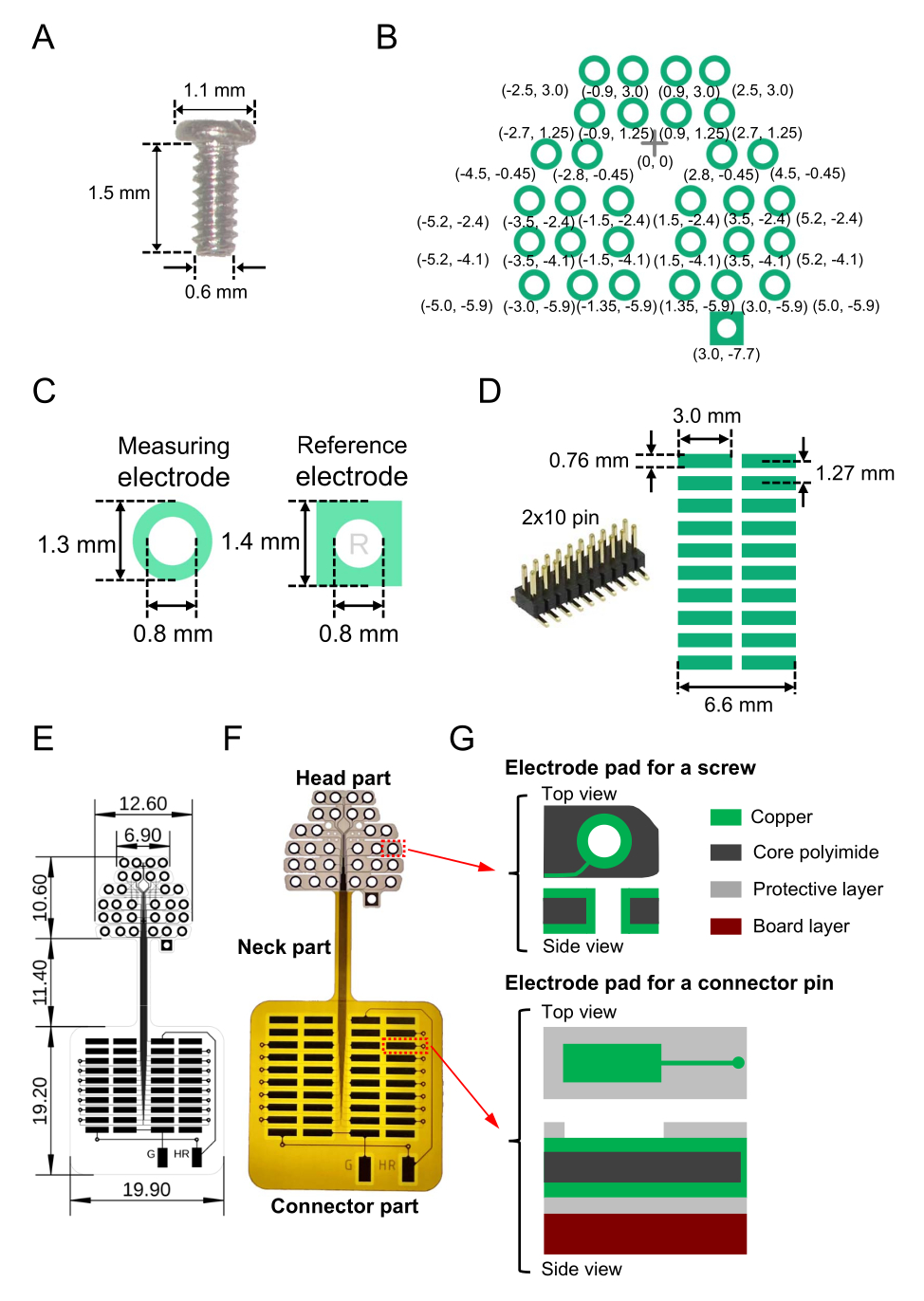
- Prepare the required number of miniature screw electrodes (stainless, SUS XM7; see Table of Materials) with the following structural properties for use as EEG recording and reference electrodes: nominal diameter, neck length, and head diameter of 0.6 mm, 1.5 mm, and 1.1 mm, respectively (Figure 1A).
NOTE: In the present study, 16 miniature screw electrodes were used. - Prepare a blueprint of a printed circuit diagram on a flexible substrate following the steps below.
- Create a two-dimensional (2D) electrode pad pattern on a flexible substrate (whole size, 41.2 mm × 19.9 mm; see Table of Materials) for the screw electrodes to be read out. Design the 2D electrode arrangement. Figure 1B shows the specific arrangements used in this study and the relative coordinates from a baseline point (cross marked at the origin [0, 0]).
NOTE: In the present study, to record neural activity in the auditory cortex within the temporal lobes, electrode placement in the lateral-to-medial (horizontal) direction was longer than that in the rostral-to-caudal (vertical) direction (Figure 1B). - Ensure that for the EEG recording electrodes, each copper pad (see Table of Materials) on the flexible substrate has a ring shape with an outer diameter of 1.3 mm and an inner diameter of 0.8 mm (Figure 1C, left). Make a small hole (0.8 mm diameter) in the center for each screw electrode to pass through the substrate. For the reference electrodes, each copper pad should have a square shape with a side length of 1.4 mm; similarly, make a small hole (0.8 mm diameter) in the center for each screw to pass through the square pad on the substrate (Figure 1C, right).
- Next, to solder a surface-mount connector (Figure 1D, left), design readout pads (2D array) leading to the connector (Figure 1D, right). For example, use a connector with 2 × 10 pins and a 1.27 mm pitch between adjacent pins (Figure 1D, right).
- Wire the screw electrode pads and connector pads using both the surface and back layer with a line width of 0.03 mm and line interval of 0.03 mm (thin lines in Figure 1E).
- Furthermore, to connect the reference and ground channels to the amplifier, connect the electrode pads for the reference and ground electrodes to the isolated part at the outside of the flexible 2D array (two vertical rectangles indicated by "G" and "HR" at the bottom of Figure 1E). After determining the reference and ground channels, remember to solder the electrode pads to the corresponding connectors (see step 2.1).
- Properly design an exposed area that is not covered with a protection layer (polyimide layer). Expose the connector pads in the surface layer while exposing the screw electrode pads in both the surface and back layers. The whole electrode design, sizes, and fabricated flexible 2D array are illustrated in Figure 1E, and the image of a fabricated substrate is shown in Figure 1F.
- In the top electrode part (head part) of the flexible 2D array, ensure that the three-layered structure from top to bottom is composed of the following (total thickness of 49.0 µm): a top copper layer (12.0 µm thickness), a middle layer of core polyimide (25.0 µm), and a bottom copper layer (12.0 µm) (Figure 1G, top).
- Etch the copper layers on the top and bottom surface of the substrate, for example, using wet etching and the standard fabrication technique9.
- In the bottom square pad part (connector part) of the flexible 2D array, ensure that the six-layered structure is composed of three layers, including a top copper layer (12.0 µm thickness), a middle core polyimide layer (25.0 µm), and a bottom copper layer (12.0 µm), which are sandwiched by protective polyimide layers, including top and bottom (both 12.5 µm) layers. Attach a 2 mm polyimide board from the bottom as reinforcing material (Figure 1G, bottom).
NOTE: To maintain flexibility, the reinforcing polyimide board is not mounted to the neck part of the flexible 2D array between the head and connector part. - Similarly, in the connector part, etch the copper and protective polyimide layers on the top using wet etching and the standard fabrication technique.
NOTE: The total weight of the fabricated, flexible, 2D array device, including the connector, is 0.84 g. After designing a layout for a flexible 2D array, the substrates from a commercial manufacturer (see Table of Materials) are sometimes recommended for convenience.
- Create a two-dimensional (2D) electrode pad pattern on a flexible substrate (whole size, 41.2 mm × 19.9 mm; see Table of Materials) for the screw electrodes to be read out. Design the 2D electrode arrangement. Figure 1B shows the specific arrangements used in this study and the relative coordinates from a baseline point (cross marked at the origin [0, 0]).

Figure 1: Component parts of the flexible two-dimensional (2D) array for electroencephalographic (EEG) recording and the fabricated device including the array. (A) The miniature screw electrode that is embedded in the mouse skull. (B) The designed electrode pads for measuring brain activity (green circles) and the reference channel (square on the bottom right). The relative coordinates of the electrode pads from a reference point (cross mark) at the origin (0, 0) are shown; the size in millimeters is illustrated in parentheses. The center coordinates of the electrode pads are symmetrical with respect to the vertical axis passing through the cross mark. (C) The electrode pads and drill holes for a recording electrode (left) and a reference electrode (right) are illustrated. (D) A surface-mount connector (2 × 10 pins) used for the flexible 2D array (left) and the pattern and size of the designed pads on the substrate (right). (E) Designed blueprint with the size of each part in millimeters. (F) Image of a fabricated substrate indicated by the blueprint in E. (G) The layer structure of the flexible 2D array (head and connector parts). The top and side views of the screw electrode pads (top) and readout pads (bottom) are illustrated. The head and the connector parts are composed of a three-layered structure (top) and a six-layered structure (bottom), respectively. Additionally, the neck part is composed of a five-layered structure; a protective polyimide layer is mounted on the top and back surface, and the reinforcing polyimide board is not mounted on the neck part. Please click here to view a larger version of this figure.
2. Adaptor construction and channel mapping
- Perform adaptor construction following the steps below.
- Spread soldering flux on the 2 × 10 pin, surface-mount connector (Figure 1D, left) and the connector pads of the 2D array (Figure 1D, right) (see Table of Materials) on the flexible substrate.
- Solder the 2 × 10 pin, surface-mount connector to the connector pads. In particular, confirm the connection between the two pads on the lower part of the 2D array and the two connector pins used as reference and ground channels (Figure 2A).
- Connect each of the two pads to individual lead wires to feed baseline signals to an external point (e.g., a ground point connected to the ground channel of the measurement system; Figure 2A).
NOTE: In this study, however, one of the circular electrode pads with screw electrodes was used as a reference electrode instead of a square electrode in the connector part. - After soldering, cover the soldering points using epoxy resin (see Table of Materials) to protect the exposed points and prevent short circuits.
- Pin the connector cable and head amplifier following the steps below.
- Prepare an insulation-displacement connector (IDC) with 2 × 10 pins and a 1.27 mm pitch (Figure 2B, top left) and a flat 20 pin ribbon cable (see Table of Materials) with a 0.635 mm pitch (Figure 2B, bottom left). Cut the flat ribbon cable to the required length (e.g., 40 cm).
- Crimp the IDC and one end of the flat ribbon cable using an IDC crimping tool (Figure 2B, top right) (see Table of Materials).
- Separate each line of the other end of the cable up to approximately 15 mm from the tip end using a cutter. Strip the insulation 3 mm from the tip end.
- Connect the crimped IDC to the flat ribbon cable and the 2 × 10 pin connector soldered to the flexible substrate (Figure 2C).
- Confirm the correspondence between the recording electrode and the separated line of the cable. Ensure that each line used does not produce an incorrect connection error.
- Solder the exposed copper wires of the individual lines corresponding to the output of each electrode to the 20 pin connector (1.25 mm pitch) of the measurement system, including the main amplifier (Figure 2B, bottom right).
- After soldering, confirm conduction between the screw electrode pads and the connector pins using a testing equipment (e.g., an LCR meter; see Table of Materials).
- Cover the soldering points using epoxy resin and shielding tape to protect them from damage and prevent contact with other signal lines.
- Using epoxy resin, adhere a thin stainless-steel rod (diameter: 1.1-1.2 mm; length: 100 mm) to the back side of the connector part of the 2D array on the flexible substrate.
NOTE: This stainless-steel rod can be grasped by a micromanipulator holder during experiments (Figure 2C). - Finally, confirm the mapping between the screw electrodes and signal output channels (Figure 2D).

Figure 2: Constructing the adaptor for a two-dimensional (2D) electrode array on the flexible substrate and recording channel mapping. (A) In the connector part, the reference and ground channels are connected to the bottom electrode pads with lead wires. If the reference and ground channels are determined in advance, the channels should be connected to the corresponding bottom electrode pads during the design phase. In such cases, soldering lead wires to the channels and electrode pads is unnecessary. (B) Insulation-displacement connectors (top left) are crimped to one end of the flat cable (bottom left) to link the measurement amplifier connector (top right). All lines that correspond to the channels to be used are soldered to the green connectors (bottom right). In this case, because each green connector connected to the head amplifier is assigned for an eight-channel measurement, at least two connectors are needed to record 16-channel brain activity signals.The soldered points are covered with epoxy resin and shielding tape to prevent contact with other signal lines. (C) The connector and fabricated cable are placed on the surface of the flexible 2D array substrate. The thin stainless-steel rod is attached to the back side of the flexible substrate. (D) The spatial locations of recording channels on the mouse brain surface and the channel maps for each point for the measurement system are shown. In this case, there are 16 recording channels with screw electrodes (red circles), although the total number of possible recording sites is 32. The other 16 non-recording channels are also shown as green circles on the brain surface. In the mapping plot, "G" and "R" indicate the channels designed for ground and reference electrodes, respectively. Please click here to view a larger version of this figure.
3. Animal surgery
- Prepare the sterile surgical environment.
- Wear protective equipment, such as latex gloves, during the whole experimental procedure involving animals.
- Sterilize the stereotaxic apparatus and surgical instruments (see Table of Materials).
- After sterilizing the surgical instruments, wash them using sterile saline.
- Anesthetize the animals.
- Measure the weight of the mouse before surgery. Administer atropine sulfate (0.04 mg/kg; see Table of Materials) via intraperitoneal injection.
- Anesthetize the mouse via an intraperitoneal injection of a mixture of medetomidine (0.3 mg/kg), midazolam (4.0 mg/kg), and butorphanol (5.0 mg/kg).
- Confirm the anesthetic depth by the level of response via pinching the toe.
NOTE: The anesthesia will wear off after approximately 40 min. If the mouse responds to a toe pinch, administer the same dose of the anesthetic mixture via an intraperitoneal injection.
- Pre-prepare for the electrode implantation surgery.
- Cut the mouse whiskers to prevent haptic sensation.
- Lubricate both eyes with an ophthalmic ointment to prevent drying. Close the eyelids to obstruct the sense of sight and maintain closure by adhering the upper and lower eyelids with mending tape.
- Shave the hair on the head of the mouse with electric clippers. Insert a thermometer into the rectum and maintain the body temperature at 37 °C using a heating pad.
- Administer lidocaine hydrochloride as a topical local anesthetic to the part of the mouse scalp that will be incised.
- Incise the mouse scalp using a scalpel or surgical scissors in a rostral-to-caudal direction (area size: 7 × 10 mm2).
- Pinch the scalp near the incised part with tweezers and lift. Remove the visible membrane on the skull using a scalpel or surgical scissors. Do not break the blood vessels around the eyes during the operation.
- Grasp the skin near both centers of the incision line of the scalp with forceps and widen the incised part to widely expose the top of the skull.
- Confirm the complete removal of all membranes on the surface of the skull and the tissue around lambda with surgical scissors.
- Wet the skull surface with physiological saline to enhance the visibility of the brain surface under the skull and locate the transverse sinus.
NOTE: When implanting screw electrodes into the skull, remember not to embed them above and into the transverse sinus.
4. Electrode implantation
- Attach the stainless-steel rod mounted to the 2D electrode array on the back side of the flexible substrate to a micromanipulator. Place the flexible substrate on the skull.
- Adjust the location of channels (Chs) 3 and 14 (Figure 2D) on the array to fit within the inferior colliculus.
NOTE: The inferior colliculus is located along the transverse sinus. We recommend confirming the location of the inferior colliculus using a mouse brain atlas in advance. - Draw small circles at the locations of Chs 3, 8, 9, and 14 (Figure 2D) on the skull with a permanent marker to use as targeting landmarks.
- Dry the skull surface to enhance adherence to the dental cement and to electrically isolate the 2D electrode array on the flexible substrate from the mouse skull.
- Apply dental cement (approximately 1 mm thickness; see Table of Materials) to the skull surface. After applying the dental cement, wait approximately 30 min for it to cure.
- Align the flexible substrate according to the small circular marks on the surface of the skull.
- Align the tip of a dental drill to each electrode pad hole on the flexible substrate. Drill carefully into the skull through each of the electrode pad holes.
- Screw each of the miniature screw electrodes through the drilled holes in the skull using a dedicated screwdriver for miniature screws.
- Crimp the head of the screw electrode and the electrode pad tightly. Finally, measure the conductance between each screw electrode and the connector with testing equipment (e.g., an LCR meter) to confirm electrical conductivity.
5. Small coil design and construction
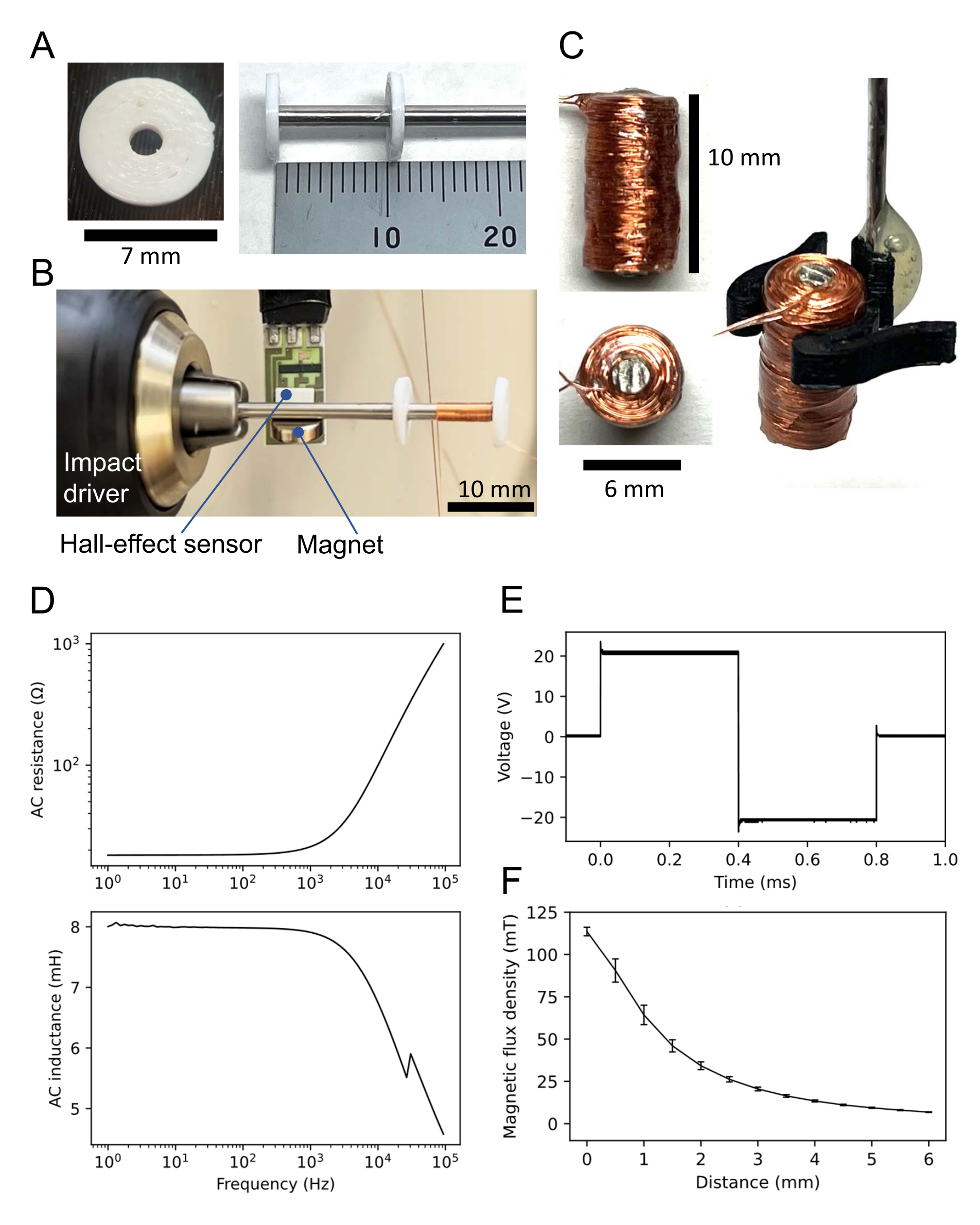
- Design a donut-shaped disk (see Supplementary Coding File 1) with a hole in the center (inner diameter: 2 mm; outer diameter: 7 mm; thickness: 1 mm) using computer-aided design (CAD) software (see Table of Materials).
- Using a 3D printer, print two disks (Figure 3A, left) made of non-heat-resistant material (e.g., poly-lactic acid filament); non-heat-resistant material is not always necessary (see below).
- Trim a permalloy-45 rod (diameter: 2 mm; see Table of Materials) to form a short shaft (length: 60 mm).
- Insert the shaft into each hole of the two 3D-printed disks (Figure 3A, right). Place one disk at the end of the shaft and the other 11 mm from the end, resulting in a 10 mm distance between the two disks. Adhere the disks with instant glue (see Table of Materials).
- Attach the end of the shaft without a disk to an impact driver (Figure 3B). Attach a small magnet to the permalloy-45 shaft. Place a hall-effect sensor near the magnet 5 mm from the shaft. Connect the hall-effect sensor to a data acquisition (DAQ; see Table of Materials) system.
- To count the number of turns, prepare a computer program (see Table of Materials) that analyzes output signals from the hall-effect sensor through the DAQ system.
- Connect a thin copper wire (diameter: 0.16 mm) to the shaft and adhere to the top end of the wire with instant glue.
- Using the impact driver, wind the copper wire for 1,000 turns between the two disks. Although the rotation speed is arbitrary, approximately 5 rotations per second is typically used. Then, adhere to the wound wire with instant glue.
- Detach the two disks from the shaft. If the disks are adhered strongly to the shaft, melt the disks using a heat gun.
- Cover the coil with epoxy resin to insulate and secure the surface. Then, cut off the unwound shaft portion as excess.
- Ensure that the obtained coil has height of 10 mm and a diameter of 6 mm (Figure 3B, left). For coil manipulation, either construct a coil holder (Figure 3C, right) or adhere a stainless-steel rod to the coil (not shown here).
- Measure the resistance and inductance of the coil using an LCR meter (see Table of Materials). For example, the coil used here had a direct current (DC) resistance of 18.3 Ω and an inductance of 7.9 mH at 1 kHz alternating current (AC) input. The AC properties (resistance and inductance) are shown in Figure 3D.
- Use a function generator to apply a bipolar square wave to the coil. The typical amplitude of the input voltage is 20 V through a bipolar power supply with a 10x gain, following a 2 V generator output. The resulting waveform is a bipolar square wave with an approximate amplitude of 20 V (i.e., a peak-to-peak voltage of 40 V) (Figure 3E).
- Measure the magnetic flux density using the hall-effect sensor and the DAQ system. In this case, for example, the magnetic flux density (B) of the coil was 113.6 ±2.5 mT (mean ± SEM) when the coil bottom was in contact with the hall-effect sensor (Figure 3F).

Figure 3: Small coil for magnetic stimulation. (A) Three-dimensional (3D)-printed disk (left). Two identical disks are adhered to the permalloy-45 shaft; one is at the end of the shaft, and the other is 10 mm away (right). (B) Setup for winding the coil. The 60 mm shaft with the two disks is attached to an impact driver. A hall-effect sensor is placed near the small magnet attached to the shaft. The copper wire is wound between the two disks. (C) Constructed coil. The coil is 10 mm in height, 6 mm in diameter, and has 1,000 turns of copper wire. The right side of the figure shows the coil manipulated by a 3D-printed coil holder. (D) AC properties of the coil recorded by an LCR meter: (top) resistance versus frequency of sinusoidal input; (bottom) inductance versus input frequency. A typical coil has a resistance and inductance of 21.6 and 7.9 mH, respectively, at 1 kHz of AC input. (E) Biphasic rectangular waveform used as the coil input recorded by an oscilloscope. (F) Relationship between magnetic flux density and the distance between a constructed coil and the hall-effect sensor. The magnetic flux density was recorded by five different hall-effect sensors, once for each sensor. The average of five measurements is plotted, and error bars represent the standard errors of the mean. Please click here to view a larger version of this figure.
6. Signal recording system and procedure
- Connect the flexible 2D array to the recording system (see Table of Materials) with the flat ribbon cable.
- Attach the stainless-steel rod mounted on the coil to a micromanipulator (see Table of Materials).
- Place the coil above bregma and adjust the position in the caudal direction to locate the focal point above the inferior colliculus. The focal point of the emitting electric field is the midline of the wound area on the bottom surface of the coil (i.e., 1 mm from the edge to the center).
- Prepare a stimulation system consisting of a bipolar power supply and a function generator (see Table of Materials) and connect the coil to the system.
- Connect a cable between the input terminal of the function generator and the output terminal of the DAQ system to apply trigger signals to the function generator from the DAQ system. Prepare an appropriate computer program for trigger signals to initiate stimuli. Additionally, connect the DAQ system to the recording system to save the stimulation times as timestamps.
- Start the acquisition process for the recording system.
NOTE: If the recording system is picking up noise, find the source of the noise and reduce it. - Test the magnetic stimulation by triggering the stimulation system.
NOTE: If the noise produced by the magnetic stimulation saturates the measurement range, adjust the range properly. Additionally, confirm that the recording system saves the stimulation timestamps properly. - Start recording the response data and begin stimulation sessions. Stop the recording when each stimulation session is complete. Save all recorded data for subsequent analysis.
NOTE: To perform all experimental conditions with five different magnetic intensities, for example, the total time required for all sessions was about 75 min. The endpoint was usually determined after all the recording sessions were over. However, when the animals showed clinical signs including coughing, labored breathing, and gasping, the experimental session was immediately terminated. For euthanasia, decapitation was performed using sharp, clean scissors while animals were under anesthesia.
7. Data analysis
- Filter the wideband (raw) signal using a low-pass filter with a cut-off frequency of 200 Hz.
- Collect filtered waveforms during a time window around each stimulation timestamp. Average the waveforms to obtain the event-related potential (ERP) waveforms (Figure 4 and Figure 5).
Results
Sample EEG data recorded in anesthetized C57BL/6J mice with the flexible substrate combined with the screw electrodes are presented below.
As a typical example, the average EEG waveforms generated in response to sound stimulation (8 kHz tone-burst, 80 dB sound pressure level [SPL]) are shown for 60 trials with identical stimuli (Figure 4A). A schematic of recording channel mapping is also presented in the middle of Figure 4A. The resp...
Discussion
This study addresses a multi-site EEG recording system combined with a magnetic stimulation system designed for small animals, including mice. The constructed system is low-cost and easily constructed in physiological laboratories, and can extend their existing measurement setups. The surgical procedure necessary to obtain data from the mouse recording system is profoundly simple if such laboratories have previous experience with standard electrophysiological experiments.
One advantage of usin...
Disclosures
The authors have nothing to disclose.
Acknowledgements
This work was supported by the Murata Science Foundation, the Suzuken Memorial Foundation, the Nakatani Foundation for Advancement of Measuring Technologies in Biomedical Engineering, and a Grant-in-Aid for Exploratory Research (grant number 21K19755, Japan) and for Scientific Research (B) (grant number 23H03416, Japan) to T.T.
Materials
| Name | Company | Catalog Number | Comments |
| 3D printer | Zhejiang Flashforge 3D Technology Co., Ltd | FFD-101 | The printer used for 3D-printing the donut-shaped disks |
| ATROPINE SULFATE 0.5 mg | NIPRO ES PHARMA CO., LTD. | - | Atropine sulfate |
| Bipolar amplifier | NF Corp. | KIT61380 | For amplifying waveforms for coil input |
| Butorphanol | Meiji Seika Pharma Co., Ltd., Tokyo, Japan | - | For anathesis of animals |
| Commercial manufacturer of flexible 2D array | p-ban.com Corp. | - | URL: https://www.p-ban.com/ |
| Computer prograom to analyze output signals | Natinal Instruments | NI-DAQ and NI-DAQmx Python | To analyze output signals from the hall-effect sensor |
| Connector | Harwin Inc. | G125-FV12005L0P | For connector to conect to the measuring system |
| Copper pad | p-ban.com Corp. | copper | Copper pad on each substrate |
| Copper wire | Kyowa Harmonet Ltd. | P644432 | The windings of the coil |
| DAQ board | National Instruments Corp. | USB-6343 | For measuring the magnitic flux density of the coil |
| Dental cement | SHOFU INC. | Quick Resin | Self-Curing Orthodontic Resin |
| ECoG electrode | NeuroNexus Inc. | HC32 | For reference to design of the flexible 2D array |
| Epoxy resin | Konishi Co. Ltd. | #16123 | For coil construction |
| Ethyl Carbamate | FUJIFILM Wako Pure Chemical Corp. | 050-05821 | For urethan anesthesia |
| Flat ribbon cable | Oki Electric Cable Co., Ltd. | FLEX-B2(20)-7/0.1 20028 5m | For cable to connect between surface-mount connector and measuring sysytem |
| flexible substrate | p-ban.com Corp. | polyimide | Baseplate of flexible substrate |
| Function generator | NF Corp. | WF1947 | For generating waveforms for coil input |
| Hall-effect sensor | Honeywell International Inc. | SS94A2D | For measuring the magnitic flux density of the coil |
| IDC crimping tool | Pro'sKit Industries Co. | 6PK-214 | To crimp the IDC and one end of the flat ribbon cable; Flat cable connector crimping tool |
| Instant glue | Konishi Co. Ltd. | #04612 | For coil construction |
| Insulation-displacement connector (IDC ) | Uxcell Japan | B07GDDG3XG | 2 × 10 pins and a 1.27 mm pitch |
| LCR meter | NF Corp. | ZM2376 | For measuring the AC properties of the coil |
| Manipulator | NARISHIGE Group. | SM-15L | For manipulating the coil |
| Medetomidine | Kobayashi Kako, Fukui, Japan | - | For anathesis of animals |
| Midazolam | Astellas Pharma, Tokyo, Japan | - | For anathesis of animals |
| Miniature screw | KOFUSEIBYO Co., Ltd. | S0.6*1.5 | For EEG-senseing and reference electrode |
| Mouse | Japan SLC, Inc. | C57BL/6J (C57BL/6JJmsSlc) | Experimental animal |
| Permalloy-45 rod | The Nilaco Corp. | 780544 | The core of the coil |
| Recording system | Plexon Inc. | OmniPlex | For EEG data acquisition |
| Stainless wire | Wakisangyo Co., Ltd. | HW-136 | For grasp by manipulator |
| Stereotaxic apparatus | NARISHIGE Group. | SR-5M-HT | To fix a mouse head |
| Surface-mount connector | Useconn Electronics Ltd. | PH127-2x10MG | For connector to mount on the flexible 2D array |
| Testing equipment (LCR meter) | NF Corp. | ZM2372 | Contact check and impedance measurements |
| White PLA filament | Zhejiang Flashforge 3D Technology Co., Ltd | PLA-F13 | The material used for 3D-printing the donut-shaped disks |
| Xylocaine Jelly 2% | Sandoz Pharma Co., Ltd. | - | lidocaine hydrochloride |
References
- Ilmoniemi, R. J., et al. Neuronal responses to magnetic stimulation reveal cortical reactivity and connectivity. Neuroreport. 8 (16), 3537-3540 (1997).
- Hallett, M. Transcranial magnetic stimulation: a primer. Neuron. 55 (2), 187-199 (2007).
- Thut, G., Pascual-Leone, A. Integrating TMS with EEG: How and what for. Brain Topography. 22 (4), 215-218 (2010).
- Ilmoniemi, R. J., Kicic, D. Methodology for combined TMS and EEG. Brain Topograpy. 22 (4), 233-248 (2010).
- Daskalakis, Z. J., Farzan, F., Radhu, N., Fitzgerald, P. B. Combined transcranial magnetic stimulation and electroencephalography: its past, present and future. Brain Research. 1463, 93-107 (2012).
- Tremblay, S., et al. Clinical utility and prospective of TMS-EEG. Clinical Neurophysiology. 130 (5), 802-844 (2019).
- Pellicciari, M. C., Veniero, D., Miniussi, C. Characterizing the cortical oscillatory response to TMS pulse. Frontiers in Cellular Neuroscience. 11, 38 (2017).
- Lin, Y. J., Shukla, L., Dugue, L., Valero-Cabre, A., Carrasco, M. Transcranial magnetic stimulation entrains alpha oscillatory activity in occipital cortex. Scientific Reports. 11 (1), 18562 (2021).
- Takahashi, S., et al. Laminar responses in the auditory cortex using a multielectrode array substrate for simultaneous stimulation and recording. IEEJ Transactions Electrical and Electronic Engineering. 14 (2), 303-311 (2019).
- Yoshikawa, T., Higuchi, H., Furukawa, R., Tateno, T. Temporal and spatial profiles of evoked activity induced by magnetic stimulation using millimeter-sized coils in the mouse auditory cortex in vivo. Brain Research. 1796, 148092 (2022).
- Tang, A. D., et al. Construction and evaluation of rodent-specific rTMS coils. Frontiers in Neural Circuits. 10, 47 (2016).
- Li, L. Controlling annealing and magnetic treatment parameters to achieve high permeabilities in 55 Ni-Fe toroid cores. IEEE Transactions on Magnetics. 37 (4), 2315-2317 (2001).
Reprints and Permissions
Request permission to reuse the text or figures of this JoVE article
Request PermissionExplore More Articles
This article has been published
Video Coming Soon
Copyright © 2025 MyJoVE Corporation. All rights reserved