
Buckling of Steel Columns
Overview
Source: Roberto Leon, Department of Civil and Environmental Engineering, Virginia Tech, Blacksburg, VA
In the design of civil works, it is important to deliver structures that are not only safe under unexpected loads, but also provide excellent performance under everyday loads at a reasonable economic cost. The latter is often tied to minimum use of materials, ease of fabrication, and rapid construction in the field. Structures made of steel members can be very economical because of the great strength of the material and the extensive prefabrication of their members and connections, which help maximize the speed of construction on site. Generally, the skeleton of a steel structure will be very slender as compared to a reinforced concrete one. While its behavior in tension is governed primarily by the strength of the material, steel in compression is governed by another failure mode common to all materials- buckling. This behavior is easily demonstrated by pressing down on a slender wooden ruler, which under a compressive load will suddenly move sideways and lose load carrying capacity. This phenomenon will occur in any slender member of a structure. In this lab, we will measure the buckling capacity of a series of slender aluminum columns to illustrate this failure mode, which over time has led to many catastrophic failures including that of the Quebec River Bridge, which was erected in 1918.
Principles
Since the phenomenon of buckling is easily observable, it was well known since antiquity, but analytical insights into the problem of buckling did not gain attention until the 1700s when the mathematical underpinnings of physics became a popular subject of study. Leonhard Euler, a famed Swiss mathematician, was the first to provide the solution to the buckling load of a simply supported column in 1742. Euler formulated his solution by reasoning that a perfectly straight column could be in equilibrium in two configurations: an undeformed one and a deformed one (slightly bent position).
For the deformed column, Euler postulated that the equilibrium in a slightly bent configuration in which the external moments, given by the load P acting at an eccentricity y, are balanced by the internal moments (M):
 (Eq. 1)
The quantity y is the lateral displacement along the length z. The first derivative of y is the slope, and the second derivative of y is the curvature of the member. The internal resistance is proportional to the curvature, or to the internal moment divided by the bending stiffness (EI), so that:
 (Eq. 2)
In this equation E is the modulus of elasticity and I is the moment of inertia, a geometrical property of the section. Substituting (Eq. 2) into (Eq. 1) and setting it equal to zero gives the traditional differential equation of buckling, where y is the horizontal deformation, and k is a substitution variable used to simplify the equations.
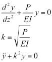 (Eq. 3)
If we assume that the column deformation along its length z is given by:
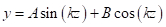 (Eq. 4)
and that the column has pinned ends, and that these ends do not displace laterally with respect to one another, then the boundary condition at z = 0 and L, the lateral displacement, is zero. Thus,
 (Eq. 5)
where N= 1,2, …. The lowest value for N is 1, which is the elastic buckling load (P critical or P cr). For a column with pinned ends, (i.e. with ends free to rotate, but not translate as the given boundary conditions above) Pcr is given by the Euler buckling load:
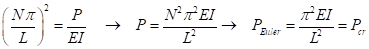 (Eq. 6)
It is important to note that this equation does not contain any terms related to the strength of the material, only to its modulus of elasticity (E), dimensions, and length. The moment of inertia (I) of a section made up of rectangular parts is given by the summation about the centroid of the section of two components: the moment of inertia of the individual rectangle (bd3/12) plus its area (A) times its distance from the centroid of the entire section (d):
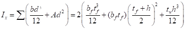 (Eq. 7)
Eq. 7 highlights that the value of I can be increased significantly by putting most of the material as far away from the centroid as possible (i.e. by maximizing d). For example, for a fixed total area of 13 in.2, one could opt for two distributions: (a) one single rectangle of 13 in. x 1 in., resulting in a total I of 183 in.4, or (b) a W-shaped section with two flanges of 6.5 in. x 0.45 in. connected with a web of 0.35 in. x 19.1 in., resulting in a total I of 761 in.4. Clearly the W-shape will be a much more efficient use of the material with respect to compression, as it will provide over 4 times greater buckling capacity. The actual standard AISC W-shape with an area of 13 in.2, a W21x44 (nominal depth of 21 in. and a weight of 44 lbs. per foot) provides an I of 843 in.4 or over 4.5 times that of the rectangular section.
The relationship between the moment of inertia (I) and area (A) is defined by the radius of gyration (r):
 (Eq. 8)
The buckling capacity is sometimes expressed as a critical stress (Fcr) by dividing the critical load by the area:
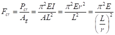 (Eq. 9)
One needs to keep in mind that there are some limitations inherent in the derivation of Eq. (6) and Eq. (9) in that they assume:
- Purely elastic behavior, and thus they are valid only up to the proportional limit of the material.
- The load is applied at the centroid of the column, which is hard to achieve in practice. Thus, accidental initial eccentricities will play a role in design.
- The column is initially perfectly straight. Since steel shapes are produced by a rolling process, they will have a camber and sweep (i.e., they will be slightly curved along both principal axes). These initial imperfections are small, on the order of L/1000, but will make real column behavior deviate from that of an idealized column.
- A deflected shape, which in our case took the form of a trigonometric function (i.e., a combination of sine and cosine functions). For this case, we actually used the correct analytical solution, but that is not always possible. In general, any function approximating the correct solution will give a satisfactory approximate, but not an exact solution.
- Idealized end conditions. In order to solve for the buckling load, the boundary conditions to the mathematical problem have to be established, and we assumed that the column had pinned ends. In addition, it was assumed that the ends of the column did not translate laterally with respect to one another (i.e., this is the sway-prevented case, which occurs in braced frames, as opposed to the sway-permitted case, which occurs in unbraced frames). In real life, these idealized conditions can only be approximated.
- The absence of any residual stresses, which arise from the cooling and rolling of the steel shapes during production. These stresses results in yielding earlier than expected and the loss of moment of inertia, as the sections yielding have a modulus of elasticity of zero. As the column stiffness decreases, the capacity of the column has to decrease, since Eq. 1 has EI in the numerator.
The second, third, and last limitations are generally treated together as initial imperfections, and their magnitudes are keyed to established construction and fabrication tolerance. Column design curves have been developed that address these issues satisfactorily.
A structural/mechanical system is said to be imperfection sensitive if the load carrying capacity of the imperfect system is substantially less than that of the perfect system. Conversely, a system is said to be imperfection insensitive if there is no loss of loadcarrying capacity because of the imperfections. A column is said to be a perfect column if it is straight, and the load is concentric. While this is impossible in practice, we are fortunate because columns are imperfection insensitive, and thus will not have any sudden loss of load carrying capacity under normal loads. On the other hand, spheres and cylinders are imperfection sensitive, and as a result, much care must be given during construction of shells (domes, cooling towers, and storage tanks) and other such structures to obtain the correct geometry. The effect of the imperfections is to accelerate the rate of lateral deflection, since they tend to increase the bending moments in the column.
The limitations related to the fifth assumption, that of the boundary conditions, can be treated simply by the use of the concept of an effective length (kL). The effective length factor k gives the proportion of the length between points of inflection (i.e., points of zero moment or zero curvature along the column). Therefore, Eq. (9) can be rewritten as:
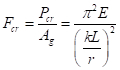 (Eq. 10)
The denominator (kL/r) is known as the slenderness of the column. A low value (for example, kL/r < 20) is synonymous with a stocky column, which is not very susceptible to buckling, while a large value (for example, kl/r > 100) is synonymous with a slender column, which is very susceptible to buckling.
It should be noted that the critical stress (σcr) for design is capped by the yield strength of the material (σy). This constraint means that for any given steel strength, say σy = Fy = 50 ksi , there will be a slenderness below which buckling will not occur. If we equate σcr = 50 ksi in Eq. (10), the limit slenderness is kl/r < 75.6.
Another important caveat is that the formulation above indicates that buckling will occur suddenly as the axial load reaches its critical value (Pcr). Mathematically, this fact indicates that buckling is a bifurcation problem. Because of initial imperfections, accidental eccentricities, and residual stresses among other factors, there will be a transition between the elastic buckling stress and the squash load. The result of these initial imperfections is that in real life there will be a smooth transition between the elastic buckling curve and the yield limit states.
At this point, it is important to note that the instability or buckling phenomenon under discussion is only one of many that can occur. Instabilities occur at both the local and global level. Global level instability is when all elements (an element is defined as any rectangular section that makes up a shape) move together during buckling. Local buckling occurs when only one of the elements moves. Examples of global buckling are:
- Flexural buckling, which is the case discussed above.
- Torsional buckling, in which the section twists about its longitudinal centroid. Sections that have small torsional stiffness (J) are prone to this type of failure.
- Flexural-torsional or lateral-torsional buckling, which is a combination of the first two types of global buckling and is the predominant instability mode for beams.
- Shear buckling, in which the buckling occurs in the thin webs of deep girders due to the formation of a tension field in the diagonal direction.
Sections can also buckle locally. This is analogous to each section of the column buckling individually as a plate. Local buckling is governed by the width-to-thickness ratio (b/t) or slenderness ratio of the section and the plate's aspect ratio (b/a, where a is the length). The slenderness depends on whether both edges of the plate are connected to another section (stiffened case), or whether only one edge is connected (unstiffened case). The buckling capacity for a plate of width b and thickness t, analogous to Eq. (10) for a column, is given by:
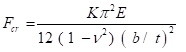 (Eq. 11)
The buckling coefficient K reflects the boundary conditions and the aspect ratio (length-to-width) of the plate. Values of K are widely available in structural design handbooks.
Procedure
- Obtain several long pieces of a 1in. by ¼ in. aluminum bar (6061 or similar), and cut them to lengths of 72, 60, 48, 36, 24, 12 and 8 in., respectively. Round both ends of the bars to a circumference of 1/8 in.
- Measure the dimensions of the bar (length, width and thickness) to the nearest 0.02 in.
- Machine two small block of steel (2 in. x 2 in. x 2 in.) to have a very smooth ½ in. circular penetration along one of its sides to serve as the column end support. Provide an insert on the opposite side, so that the block can be fixed to the testing machine.
- Insert the blocks and a test specimen into the testing machine. Be sure to align the specimen as carefully as possible to eliminate eccentricities.
- Set the testing machine on deflection control and program it to slowly apply a deformation of up to 0.2 in. and record load and axial deformation. The limit can be varied with the length, but the test should be stopped when the load has stabilized or when it has reached not more than a 20% load reduction from the maximum capacity.
- Record the maximum load reached and fill in the results table.
- Repeat steps 1.4 through 1.6 for all columns.
Results
Plot the results from the table as buckling stresses vs. slenderness (kL/r), along with the curve given by Eq. 9. Compare your results with the predicted values. The experimental results shows two distinct regions. When the columns are relatively long, the critical load is given by multiplying Eq. 9 by the area of the column. As the columns begin to get shorter, the critical load begins to approach the strength of the material. At this point the behavior shifts from a purely elastic one to a partial inelastic one that approaches asymptotically the squash load of the column. When a column buckles elastically, deformation can become every large suddenly and trigger failures either in the buckled member or in adjacent ones that become overloaded as the buckled member sheds its loads. Thus, in design it is important to prevent elastic buckling failures in primary structural members.
Application and Summary
This experiment demonstrated the validity of the Euler approach for calculating local buckling loads for simple columns. Although the problem becomes far more complicated if either the boundary conditions are not well known, the member is not prismatic, or if the material does not exhibit a bi-linear stress-strain curve, the solution of the problem follows the same general process. In many practical cases, it will not be possible to solve the resulting differential equations exactly, but there are many numerical techniques that can be applied to approximate the solution to those problems. The importance of buckling is recognized in the construction industry aphorism that holds that the successful design of steel structures is predicated on a good grasp of buckling issues, while successful design of reinforced concrete structures is based on good detailing.
Economy in design requires that the volume of material be minimized. This detail is particularly true for metal building and bridge structures, where the materials costs are a significant portion of the total structural cost. In general, minimizing cost boils down to getting the lowest L/r. For a fixed L, this means obtaining the largest possible r (or largest I for a given A), leading to the widespread use of W-shaped members. For a fixed r, this means decreasing L, which entails the use of bracing members. For a W-shape, there will be both an Ix and Iy, and corresponding (kL/r)x and (kL/r)y; for optimum design, both of these values should be close to one another, which is often obtained by providing more bracing in the y-direction. Another way of preventing buckling is to add stiffeners, which reduce the buckling lengths in plates; examples of these include stiffeners in bridge plate girders and stiffening lips in cold-form structural members.
Tags
Skip to...
Videos from this collection:

Now Playing
Buckling of Steel Columns
Structural Engineering
36.1K Views

Material Constants
Structural Engineering
23.4K Views

Stress-Strain Characteristics of Steels
Structural Engineering
109.5K Views

Stress-Strain Characteristics of Aluminum
Structural Engineering
88.6K Views

Charpy Impact Test of Cold Formed and Hot Rolled Steels Under Diverse Temperature Conditions
Structural Engineering
32.2K Views

Rockwell Hardness Test and the Effect of Treatment on Steel
Structural Engineering
28.3K Views

Dynamics of Structures
Structural Engineering
11.5K Views

Fatigue of Metals
Structural Engineering
40.7K Views

Tension Tests of Polymers
Structural Engineering
25.4K Views

Tension Test of Fiber-Reinforced Polymeric Materials
Structural Engineering
14.4K Views

Aggregates for Concrete and Asphaltic Mixes
Structural Engineering
12.1K Views

Tests on Fresh Concrete
Structural Engineering
25.7K Views

Compression Tests on Hardened Concrete
Structural Engineering
15.2K Views

Tests of Hardened Concrete in Tension
Structural Engineering
23.5K Views

Tests on Wood
Structural Engineering
32.9K Views
Copyright © 2025 MyJoVE Corporation. All rights reserved