登录

In This Article

  • Summary
  • Abstract
  • Introduction
  • Protocol
  • Representative Results
  • Discussion
  • Disclosures
  • Acknowledgements
  • Materials
  • References
  • Reprints and Permissions

Summary

This protocol combines mass photometry with a novel microfluidics system to investigate low-affinity protein-protein interactions. This approach is based on the rapid dilution of highly concentrated complexes in solution, which enables low-affinity measurements and broadens the applicability of mass photometry.

Abstract

Mass photometry is a versatile mass measurement technology that enables the study of biomolecular interactions and complex formation in solution without labels. Mass photometry is generally suited to analyzing samples in the 100 pM-100 nM concentration range. However, in many biological systems, it is necessary to measure more concentrated samples to study low-affinity or transient interactions. Here, we demonstrate a method that effectively expands the range of sample concentrations that can be analyzed by mass photometry from nanomolar to tens of micromolar.

In this protocol, mass photometry is combined with a novel microfluidics system to investigate the formation of protein complexes in solution in the micromolar concentration range. With the microfluidics system, users can maintain a sample at a desired higher concentration followed by dilution to the nanomolar range - several milliseconds prior to the mass photometry measurement. Due to the speed of the dilution, data is obtained before the equilibrium of the sample has shifted (i.e., dissociation of the complex).

The technique is applied to measure interactions between an immunoglobulin G (IgG) antibody and the neonatal Fc receptor, showing the formation of high-order complexes that were not quantifiable with static mass photometry measurements.

In conclusion, the combination of mass photometry and microfluidics makes it possible to characterize samples in the micromolar concentration range and is proficient in measuring biomolecular interactions with weaker affinities. These capabilities can be applied in a range of contexts - including the development and design of biotherapeutics - enabling thorough characterization of diverse protein-protein interactions.

Introduction

Protein-protein interactions underline most cellular functions, from immune regulation to DNA replication and translation. As a result, there is a fundamental need throughout the life sciences to investigate a vast range of interactions across diverse heterogenous complexes that are commonly formed. However, their detection, characterization, and quantification are often challenging, particularly for low-affinity interactions1.

Immunoprecipitation assays are often used to detect high-affinity interactions, but for low-affinity and transient interactions, detection is largely unfeasible2. Fluorescence techniques can also be used but require the potentially disruptive addition of fluorescent labels2. Cryo-EM can provide a structural snapshot and an ensemble readout of the protein complexes formed with high spatial resolution but also typically requires working at concentrations that are too low for imaging low-affinity interactions. Cryo-EM also brings challenges related to cost, accessibility, sample preparation, and analysis time3.

Additionally, surface plasmon resonance (SPR) has become a popular way to quantify protein-protein interactions, although it requires protein immobilization, which can affect the binding equilibrium and result in variable on-rates, thus reducing measurement accuracy4,5. It also involves several assay steps prior to data collection and analysis6.

Mass photometry is a single-molecule technique that has been used to analyze protein-protein interactions5,6,7. It works by measuring the mass of single molecules or complexes based on the light they scatter when they land on the surface of a glass coverslip8. Mass photometry measurements have been used to quantify binding affinities from the relative abundance of binding partners and the complexes they form5. Nevertheless, like other single-molecule techniques, the concentration of the sample to be measured should typically be less than 100 nM. If the concentration is higher, the molecules landing on the glass surface will overlap spatially, resulting in poor data quality7. Consequently, weaker interactions (KD ~micromolars), which dissociate at these lower concentrations, cannot be measured reliably since it is not possible to observe the necessary mixture of unbound and bound species5.

Here, we describe an approach that overcomes this limitation based on a new coupled microfluidics mass photometry device. Specifically, a microfluidics system is used in combination with the mass photometer to effectively expand the range of interactions that can be quantified by mass photometry. Microfluidics has been shown to offer a range of possibilities for investigating protein-protein interactions, including rapid dilution to detect weak interactions1,9. The system described herein operates by rapidly diluting the sample up to 10,000-fold on a microfluidic chip and immediately flowing it across the observation area of the chip, enabling the mass photometry measurement to start within 50 ms from when the molecules began the dilution process10. The dilution occurs when the sample and buffer are combined in a reverse Tesla valve mixer on the chip, with the relative flow rates of the two solutions determining the amount of dilution that occurs (see Protocol step 8). The flow rate is controllable with the microfluidic control software. Altering the flow rate can change the relative population of the species as it can impact the number of landing events on the surface of the glass, which is what is measured by the mass photometer.

The speed of the process is fast enough for the measurement to be completed before the integrity of the interaction has been disrupted (for further details, see also the Discussion). This can be understood through a brief look at the theory of first-order reactions, where figure-introduction-4451. The forward (association) rate constant is kf, the backward (dissociation) rate constant is kb, and the equilibrium dissociation constant (KD) is defined as

KD = kb / kf

For protein binding, kf is generally limited by the reactants' diffusion11 and so is restricted to the range of 106-107 M-1·s-1. Because the range of is limited, a low-affinity (KD ~micromolars) reaction will have kb ≈ 1 s-1. That is, kb = kf · KD = (106 M-1·s-1) (10-6 M) = 1 s-1, with the complex's half-life around 0.7 s11,12.

Our example system is the binding of the IgG monoclonal antibody trastuzumab to the soluble domain of the IgG neonatal Fc receptor (FcRn), which are known interacting partners13. Previously published data obtained using conventional mass photometry alone (i.e., with manual dilution of samples) showed that the proteins form multiple species. FcRn monomers, FcRn dimers, and unbound IgG were clearly visible, while IgG-FcRn complexes (at 1:1 and 1:2 ratios) were also detected (at pH 5.0) but only with very low abundance5. This observation prompts the question of whether IgG-FcRn complex formation could be more clearly detected if measured at a higher concentration. Indeed, combining mass photometry with a coupled rapid dilution approach described here provided more robust evidence of complex formation by an increase in their measured particles.

The mass photometry and microfluidics protocol described here makes it possible to characterize the formation of complexes with a KD up to the micromolar range. An empirical determination of the KD will require further improvements on the flow sensor accuracy, pump stability, chip-to-chip variations, and measurement location inside the observation window, as all these factors would influence the time from when the sample is diluted to being measured.

The same approach could be applied to investigate binding among any soluble proteins, provided they have distinct molecular weights (separated by at least 25 kDa) that fall into the range suitable for analysis with a mass photometer (30 kDa to 6 MDa). The insights obtained could be helpful for studies in a range of contexts - from gaining a mechanistic understanding of cellular functions to the design of new biotherapeutic drugs.

Protocol

1. Preparing the instruments and launching the software

  1. Turn on the mass photometer and leave it on for at least 1 h before starting any measurements.
    NOTE: This is because the instrument needs to reach a constant temperature. Not leaving the mass photometer on for 1 h could lead to a mass shift and, therefore, inaccurate results.
  2. Turn on the anti-vibration table by switching the power on and pressing the isolation button (under the mass photometer). Vibrations limit the performance of the mass photometry instrument, so the anti-vibration table is important to ensure maximum instrument sensitivity. Turn on the microfluidics box.
  3. Launch the data acquisition software and the microfluidics control software. Turn on the air compressor. 

2. Preparing protein samples, buffer, and cleaning solutions

  1. Add 200 mL of PBS (pH 7.4) buffer to a clean 200 mL bottle and 200 mL of PBS (pH 5.0) buffer to a second 200 mL bottle.
    NOTE: The 200 mL bottles will need to be connected to the "L" Flow Unit Sensor in the next steps. Use pH 7.4 PBS buffer for the calibration measurement and pH 5.0 PBS buffer for the sample measurement.
  2. In a 0.5 mL centrifuge tube, mix IgG (2 µM) and FcRn (20 µM) in a 1:10 ratio for a total volume of 60 µL.
    1. The stock solutions for FcRn and IgG are 91.9 µM and 13.5 µM, respectively. Prepare the reaction by mixing 9 µL of stock IgG + 13 µL of stock FcRn + 38 µL of PBS (pH 5.0, room temperature [RT]) in a centrifuge tube for a total volume of 60 µL. The final concentrations for the two reactants were 2 µM for IgG and 20 µM for FcRn. Keep all protein stocks on ice throughout this process.
  3. In another 0.5 mL centrifuge tube, dispense 20 µL of the β-Amylase calibrant at 20 µM concentration.
    1. As an example, to prepare the β-Amylase calibrant used here, follow the procedure described in 2.3.1.1-2.3.1.2.
      1. Resuspend 20 mg of β-Amylase powder in the vial in 3.57 mL of PBS (5% glycerol), corresponding to 5.6 mg/mL and a molar concentration of 100 µM (as the molecular weight is 56 kDa).
      2. To dilute to 20 µM, combine 200 µL of the 100 µM stock with 800 µL of PBS (pH 7.4, RT) in a 1 mL centrifuge tube.
  4. Incubate the samples at RT for at least 30 min.
    ​NOTE: Start preparing the sample and calibrant dilutions after turning on the mass photometer. For this experiment, the samples were incubated for 120 min.
  5. In three 50 mL centrifuge tubes, aliquot: 50 mL of PBS (pH 7.4) - cleaning solution 1 (CS1), 50 mL of 0.5 M NaOH - cleaning solution 2 (CS2), and 50 mL of 100% IPA - cleaning solution 3 (CS3).

3. Experimental set-up

  1. To load the sample and calibrant, place the calibrant centrifuge tube at position 4 and the sample centrifuge tube at position 5 of the microfluidics box (Figure 1).
  2. To load the cleaning solutions, place CS1, CS2, and CS3 at positions 1, 2, and 3 of the microfluidics box (Figure 1).
    NOTE: The sample, calibrant, and cleaning solutions are connected to the multi-switch (m-switch). The m-switch is connected to the "S" flow unit sensor.
  3. Screw the cap that connects to the buffer line on to the 200 mL (pH 7.4) buffer bottle.
    NOTE: The buffer line is connected to a shut-off valve, which is connected to the "L" flow unit sensor. The shut-off valve prevents any siphoning effects that can occur when the buffer flow is stopped. Siphoning can lead to contamination of the buffer from the diluted residual fluid returning to the buffer reservoir.
  4. Place the microfluidics chip onto a preparation plate.
    Push the other tube end of the "S" flow unit sensor into the "Sample inlet" of the first channel in the microfluidics chip (Figure 1). The sample line is complete.
  5. Push the other tube end of the "L" flow unit sensor into the "Buffer inlet" of the first channel in the microfluidics chip (Figure 1). The buffer line is complete.
  6. To collect the outflow, push a tube to the "Outlet" of the first channel in the microfluidics chip; position the other end so it drains into a waste receptable flask or beaker (Figure 1).

4. Priming the sample and buffer lines with buffer

  1. Open the manual shut-off valve on the buffer line.
  2. In the microfluidics control software, set the buffer line flow rate to 1000 µL/min and ensure the buffer line pressure does not exceed 110 mbar (Figure 2). The flow will automatically start in the buffer line (Figure 1).
    NOTE: If the buffer line pressure exceeds 110 mbar, it could be due to air passing through the flow sensor. If the pressure does not go back to normal within a few seconds, there is potentially a blockage (usually due to pinched tubing at the connections). In that case, stop the flow and check the connections in the buffer line, starting at the shut-off valve.
  3. In the microfluidics control software, select position 1 of the m-switch (corresponding to the PBS buffer), then set the sample line flow rate to 8 µL/min and ensure that the sample line pressure does not exceed 350 mbar. The flow will automatically start in the sample line (Figure 1).
  4. Use a pipette tip (or other soft plastic component) to apply gentle pressure from above near the bubble(s) trapped in the chip to dislodge air bubbles and ensure they are removed through the outlet.
    ​NOTE: Make sure to remove all bubbles in the 'mixer' and 'observation area' (Figure 1) sections of the channel in use. Take care not to push too hard, as this could damage the chip.

5. Placing the microfluidics chip onto the mass photometer and finding the focus

  1. Apply a drop of microscope immersion oil on the objective of the mass photometer.
  2. Place the microfluidics chip on the holder of the mass photometer with the "Sample Inlet" facing up and hold it attached to the stage clamps (Figure 1). Make sure all tubing connections remain attached.
  3. Using the data acquisition software, move the stage to ensure that the "Observation area" of channel 1 is aligned with the objective (Figure 1).
  4. Close the mass photometer lid and press the Droplet-Dilution Find Focus option in the data acquisition software.
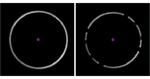
  5. Check the white focus ring in the bottom left corner of the data acquisition software (Figure 3). Gaps in the ring indicate the presence of a bubble of air in the immersion oil; remove this by increasing the stage speed to the maximum and gently moving the stage laterally.
  6. After the focusing is completed, wait 2-3 min before taking the first recording. Then, press Record to record a 1 min measurement and ensure (by observing the measurement) that no impurities appear.
    NOTE: Impurities could be on the glass surface or in the buffer. The Sharpness value in the data acquisition software should be above 4.5%.

6. Mass photometry calibration

  1. In the microfluidics control software, switch the m-switch to position 4 (corresponding to the calibrant) and ensure the sample line flow rate is set at 8 µL/min and the sample line pressure does not exceed 350 mbar (Figure 2).
    1. The calibrant will begin the flow through the chip. Wait approximately 1.5-2.5 min (or until the calibrant is seen consistently on the data acquisition software). Time may vary based on sample line tubing length.
  2. Once the calibrant is seen consistently (i.e., the number of events is sufficient for an accurate mass photometry measurement), in the microfluidics control software, reduce the flow rate to 0.5 µL/min - the target dilution level for this experiment.
    NOTE: Beginning with a higher flow rate simply reduces the time needed for the calibrant to reach the chip.
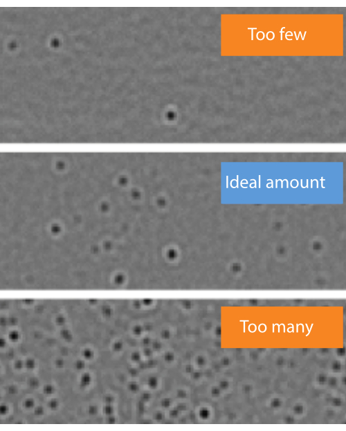
  3. Make sure that there are not "too few" or "too many" molecules landing on the measurement surface (Figure 4).
    1. If the landing event density is not "ideal" (Figure 4), change the flow rate in the microfluidics control software. If the event density is too low, increase the sample flow rate until well-separated landing events are observed (but do not exceed 8 µL/min). If it is too high, reduce the sample flow rate (but do not go under 0.1 µL/min).
    2. If the calibrant volume is running low in the sample tube, change the m-switch position to the PBS pH 7.4 line (position 1) to avoid injecting air.
  4. Press Record and take a 60 s measurement. Save the file in a chosen folder.
    ​NOTE: The data acquisition software produces files with .mp as the extension.

7. Cleaning the sample line and stopping the flow

  1. In the microfluidics control software, switch to position 2 of the m-switch and change the sample pressure to 800 mbar (Figure 2). Flush the system with CS2 (NaOH) for 4 min.
  2. Switch to position 3 of the m-switch and flush the system with CS3 (IPA) for 4 min.
  3. Switch to position 1 of the m-switch and flush the system with CS1 (PBS) for 4 min.
  4. In the microfluidics control software, stop all flow by setting the sample line and buffer line pressures to 0 and shut off the buffer valve.
  5. Disconnect the chip from the stage and place it back onto the preparation plate. Disconnect all tubing and place the sample tubing end into a waste bottle. Clean the objective with isopropanol and wipes.

8. Measuring the mass photometry sample

  1. Unscrew the cap connected to the 200 mL (pH 7.4) buffer bottle and screw it to the 200 mL (pH 5.0) buffer bottle.
  2. Repeat steps 3.4-5.6, but use the second channel of the chip instead of the first one.
  3. In the microfluidics control software, switch the m-switch to position 5 (corresponding to the sample), set the sample line flow rate to 8 µL/min, and ensure the sample line pressure does not exceed 350 mbar (Figure 2).
  4. Repeat steps 6.2-6.4 to measure the sample.
    1. To calculate the flow rates to use, ensure that the fold difference in flow rate matches the desired sample dilution factor. For example, to achieve the dilution of 2000x here, the flow rates differ by a factor of 2000; the buffer flow rate is 1000 µL/min, and the sample flow rate is 0.5 µL/min. At the end of an experiment, always leave the lines clean by following the cleaning protocol.

9. Data analysis

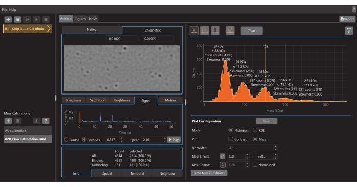
  1. Once the acquisition of data is finished, launch the data analysis software (Figure 5).
  2. Click on the plus (+) icon at the top left and select the .mp calibrant file. The software will start to analyze the loaded file. Depending on the size and number of measurements, this may take a few min
    1. Do not analyze .mp files in the data analysis software while acquiring data with data acquisition software because doing so may reduce the quality of the data being acquired.
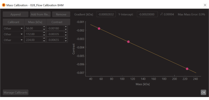
  3. Press the Create mass calibration button (bottom right). A dialog will open showing a table populated with the contrast values of the fitted peaks.
  4. Change the values to the known mass values for the fitted peaks (for β-amylase these values are 56 kDa, 112 kDa, and 224 kDa) and press Save. The newly created calibration file (.mc extension) will appear on the Mass Calibration panel (bottom left of the data analysis software) (Figure 6).
  5. Click the plus (+) icon at the top left and select the .mp sample file.
  6. To create a mass histogram, as shown in Figure 5, go to the Analysis tab, select the Histogram mode, and the Mass plot option. Adjust the Bin width, Mass Limits, and other parameters as needed.
  7. Customize the plot further in the Figures tab if desired before exporting figures and/or saving the whole workspace as a .dmp file.

Representative Results

Mass photometry was used to measure the interaction between the IgG monoclonal antibody trastuzumab and the soluble domain of the IgG neonatal Fc receptor (FcRn). A 1:10 mixture of the two proteins (at 2 µM for IgG and 20 µM for FcRn) was diluted manually to 10 nM and 20 nM in PBS, respectively.

The dilution step is necessary because mass photometry, a single-molecule mass measurement technique, can only analyze samples in the 100 pM-100 nM range. Attempting to measure samples with concentrations outside this range can jeopardize the accuracy of the results (Figure 4).This experiment is not included in this Protocol, as it has been described previously5,6.

In the mass histograms produced in a mass photometry experiment, the strength of the scattering signal (or 'contrast') for each landing event is plotted on the x-axis, and it is converted to molecular mass via the mass-contrast calibration step. Meanwhile, the y-axis indicates the number of molecules counted with a given mass (or contrast). Therefore, a peak indicates the presence of a population of molecules within the range of molecular weights shown on the x-axis. The number of events (counts) that make up the peak reflects the size of that population.

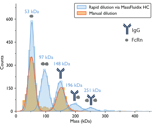
The mass photometry measurement with manual dilution resulted in a mass histogram where the two largest peaks, based on the proteins' expected molecular weights, corresponded to unbound FcRn monomers (~50 kDa) and IgG antibody monomers (~150 kDa) (Figure 7). Similar to the previously published mass photometry data5, the unbound species were prominent, while peaks in the mass ranges that would correspond to complexes were much less apparent.

The experiment was repeated using a rapid-dilution microfluidics system to dilute the mixture to the necessary concentration immediately prior to the mass photometry measurement. This approach enabled the detection of additional low-affinity complexes, which may have dissociated during the manual dilution step. To achieve the same 2000x dilution factor used during the manual dilution experiment, the 1:10 sample mixture (at 2 µM concentration for IgG and 20 µM for FcRn) was flowed onto the microfluidic chip at a rate of 0.5 µL/min, along with PBS buffer (pH 5.0) at a flow rate of 1 mL/min. To ensure that the proteins were not degraded at the time of the measurement, IgG (2 µM) and FcRn (20 µM) were measured under flow with the microfluidics system following 120 min of incubation of the samples. Individual control measurements showed no protein degradation (Supplementary Figure 1)

For the sample that underwent rapid dilution, the peaks corresponding to FcRn monomers (53 kDa), FcRn dimers (97 kDa), and IgG monomers (148 kDa) could again be observed. Also, two additional peaks were clearly observed at 196 kDa and 251 kDa, corresponding to IgG-FcRn complexes with 1:1 and 1:2 stoichiometries (Figure 7). The expected masses for these two complexes were 200 kDa and 250 kDa, respectively. The variability in the mass measurement is within the measurement error for the mass photometer used in this study is ±5%14 (2% for the 1:1 complex and 0.4% for the 1:2 complex).

The presence of these complexes in only the rapidly diluted sample is consistent with the idea that they tend to dissociate at lower concentrations, at a rate that is fast relative to a manual dilution process but slow relative to the process of rapid dilution achieved with the microfluidics system15.

figure-representative results-4026
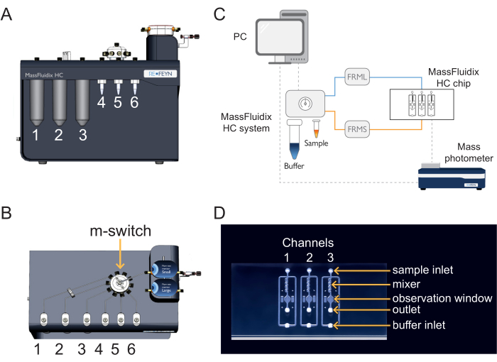
Figure 1: Combining microfluidics with mass photometry. (A,B) The microfluidics box used in this protocol, as seen from the (A) front and (B) top. The cleaning solutions are placed in positions 1-3, and the samples and calibrants in positions 4-6. All solutions are connected to the m-switch, which is connected to the "Small" flow unit sensor. (C) Overview of the entire system. The computer (top left) is connected to microfluidics box (shown adjacent to the buffer and sample tubes) and the mass photometer (bottom right), where the microfluidics chip is located. The small flow rate monitor (FRMS) monitors flow through the sample line, while the large flow rate monitor (FRML) monitors buffer flow. The sample and buffer line tubing connect to a channel on the microfluidics chip, placed inside the mass photometer. (D) Each chip has three channels. The FRMS is connected to the sample inlet and FRML to the buffer inlet. The mixer area is where rapid sample dilution takes place, while the observation area is where the mass photometry measurements are done. The outlet is monitored by an additional flow sensor to ensure there are no leaks in the chip. Please click here to view a larger version of this figure.

figure-representative results-5657
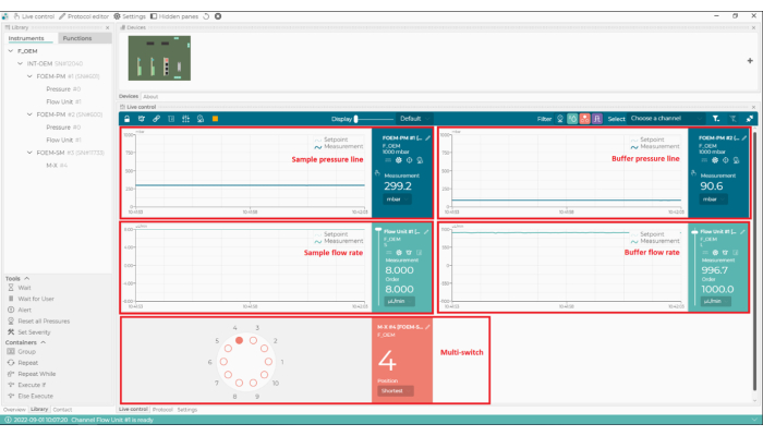
Figure 2: The microfluidics control software. With this software, set and monitor the flow rates, the pressure lines of the microfluidics system, and the position of the multi-switch (m-switch). Please click here to view a larger version of this figure.

figure-representative results-6213
Figure 3: Identifying the presence of bubbles in the oil. The examples from the data acquisition software show a clear, unbroken focus ring (left) and a 'broken' ring, indicating the presence of air bubbles in the immersion oil (right). Please click here to view a larger version of this figure.

figure-representative results-6819
Figure 4: Representative examples of sample concentrations where the number of molecule landing events is too few, ideal, or too many. Molecules landing on the surface of the observation area in the microfluidics chip will appear as dark spots in the ratiometric view of the mass photometry image. Optimally, the desired concentration should enable an ideal density of landing events to take place during data acquisition (middle). If the landing event density is too low (top, 'Too few'), accurate statistical analysis of the mass photometry data cannot be completed. If it is too high (bottom, 'Too many'), the landing molecules will overlap spatially, which will result in poor data quality. These images were captured with the data acquisition software using a mass photometer. Please click here to view a larger version of this figure.

figure-representative results-7978
Figure 5: A screen capture of the data analysis software for mass photometry. Here, the .mp files exported from the data acquisition software can be loaded to analyze the data. Figures can be generated from the processed data. Please click here to view a larger version of this figure.

figure-representative results-8566
Figure 6: A screen capture of the mass-contrast calibration for this experiment. The calibrant used was β-Amylase, which is known to form three species: monomer (56 kDa), dimer (112 kDa), and tetramer (224 kDa). Please click here to view a larger version of this figure.

figure-representative results-9144
Figure 7: Mass histograms reveal complex formation only after rapid sample dilution. Mass histograms and corresponding best-fit Gaussian distributions are shown for measurements of samples containing IgG and FcRn following manual dilution (orange) or rapid dilution via the microfluidicsHC system (blue). The mass labels indicate that the mean values from the Gaussian curves fit the mass histograms measured after rapid dilution. After manual dilution, peaks corresponding to FcRn monomers (52 kDa, as measured with manual dilution) and IgG monomers (152 kDa) were observed. After rapid dilution, in addition to the FcRn and IgG monomers, peaks corresponding to FcRn dimers and IgG-FcRn complexes with 1:1 and 1:2 stoichiometry were also clearly observed. Please click here to view a larger version of this figure.

Supplementary Data Figure 1: Mass photometry measurements of control samples after rapid dilution show no protein degradation. (A) Mass histogram and best-fit Gaussian distribution for the FcRn-only sample. The initial sample concentration prior to rapid dilution was 20 µM, and the flow rate was set to 0.5 µL/min. Mass peaks corresponding to FcRn monomers (53 kDa) and FcRn dimers (97 kDa) could be observed. (B) Mass histogram and best-fit Gaussian distribution for the IgG (Herceptin) only sample. The initial sample concentration prior to rapid dilution was 2 µM, and the flow rate was set to 1 µL/min. A single mass peak corresponding to IgG monomer (155 kDa) could be observed. Please click here to download this File.

Discussion

The protocol outlined here provides a method for detecting and quantifying low-affinity protein-protein interactions. It uses a mass photometer coupled to a rapid-dilution microfluidics system. Mass photometry is a label-free, bioanalytical tool that can reliably measure molecular mass in solution for biomolecules16, for those within the range of 30 kDa to 6 MDa. As mass photometry is a single-molecule technique that analyzes samples one by one, it is generally limited to samples in the 100 pM-100 nM concentration range. Above this range, the molecules landing on the glass surface will overlap spatially, resulting in poor data quality; below this range, too little data is obtained to do robust analysis7. An important consequence is that it can limit the investigation of protein interactions to those that form a mixture of bound and unbound species within that range.

Here, we detailed a step-by-step protocol for using a rapid-dilution microfluidics system to effectively expand the range of sample concentrations that are amenable to mass photometry. By diluting the sample on the microfluidic chip and then flowing it across the detector observation window within 50 ms, the system captures the complexes present in the undiluted sample before the interaction equilibrium shifts. The sample is continuously delivered to the detector during individual measurements. Under these conditions, 95% of the complex will remain intact when the sample is measured, even for low-affinity interactions - with a KD on the order of micromolars and dissociation rates as fast as 1 s-1.

This can be calculated as follows: For a reaction figure-discussion-1787 with a forward rate kf and backward rate kb,

figure-discussion-1991

At equilibrium, the concentrations of all three species (A, B, and the complex AB) stay constant, so figure-discussion-2229 and figure-discussion-2324. Under the conservative assumption that the perturbation (dilution, in this case) may cause the complex to dissociate, but the forward (association) reaction does not proceed, the term k[A] [B] can be treated as negligible, and the following simplification can be made:

figure-discussion-2758

Integrating gives the following expression for the concentration of complex at time after the perturbation of equilibrium:

figure-discussion-3028

The fraction of the complex that remains bound at time t after the perturbation of equilibrium is thus:

figure-discussion-3288

At = 50 ms, for a reaction with kb ≈ 1 s-1, the fraction bound is 0.95, or 95%11,12.

Mass photometry was used here and previously5 to investigate the binding of the IgG monoclonal antibody trastuzumab to the soluble domain of the FcRn. The two binding partners have been reported to bind with nanomolar affinity at acidic pH17. Mass photometry was used to qualitatively assess the abundance of the complexes formed while the binding partners were at pH 5.0, and the samples were rapidly diluted through an additional microfluidic system. The procedure was optimized for the particular protein-protein interaction based on previously reported results5. The same procedure can be used to study other interactions, provided the users have prior knowledge or optimize the experimental conditions for the system in question, such as which buffers to use, the initial protein concentration, the expected stoichiometry, and the amount of incubation needed to allow the interaction to reach an equilibrium.

When the IgG-FcRn mixture was diluted manually, it was difficult to detect the presence of IgG-FcRn complexes, even though these proteins are known to interact5. This paper shows that the rapid dilution approach results in a notably increased amount of these complexes. For the same sample, when rapid dilution was used, 1:1 FcRn-IgG complexes and 2:1 FcRn-IgG complexes were both clearly observed. These differences in complex formation demonstrate the importance of studying biomolecular interaction systems across a broad range of concentrations.

Additionally, these results also demonstrate that it is straightforward to use microfluidics with single-molecule analysis to capture weak interactions - filling a significant gap in the method. The combination of rapid-dilution microfluidics with mass photometry offers attractive advantages due to the advantages of mass photometry as an analytical technique. That is, mass photometry does not require labels, involves minimal sample preparation, and the measurements are done in solution. For this protocol, another key advantage of mass photometry is its ability to distinguish and quantify all the species formed (provided they have a distinct mass of >30 kDa). This is in contrast to SPR, for example, which can measure rates of binding and unbinding but cannot readily provide stoichiometry information8.

For this protocol, as well as mass photometry experiments more generally, several considerations are helpful. First, the final protein concentration should be within the limit of what mass photometry can measure (100 pM-100 nM). The starting incubation concentration should also be within the range of the microfluidic system (up to 90 µM) and theorized to be above the actual KD of the interaction10. The recommended starting point is a 1:1 concentration mix ratio between the interacting species at µM concentration. The ratio could then be varied to 1:2, 1:5, or, as in the case of this interaction, 1:10. If there is no previous information about the protein interactions, the user would have to optimize the experiment, starting with a high concentration (recommended 20 µM) for each partner to determine if the affinity of the components is within the concentration range sustained by the method presented (i.e., complexes are formed). Optimization might also involve choosing other buffer conditions to promote the interactions or titration of one of the interaction components to determine the right mixing ratio. Once these are determined, it is possible to optimize concentrations and flows to allow optimal conditions for the study and method, e.g., decreasing the concentrations to allow better peak resolution.

Secondly, to successfully replicate this experiment, impurities should be minimized. Common sources of impurities that are known to adversely affect mass photometry measurements include other proteins or cellular debris that remains after purification, unfiltered buffers, micelle-forming detergents (if present at too high a concentration), and buffers containing high concentrations of salt, glycerol, or other components. As discussed in the Protocol above, bubbles in the microfluidics system should be removed. Bubbles can form in the tubing system or if samples have high surface tension and are prone to foam formation. Bubbles can also form in the immersion oil, which can be detected from the focus ring (Figure 3). If bubbles cannot be removed using the steps described in the protocol, another solution is to degas the sample using a desiccator and a vacuum pump, leaving the sample under reduced pressure for a few minutes. Vortexing or shaking highly concentrated protein solutions is not recommended as these actions may promote bubble formation.

While the measurement of one specific protein-protein interaction is demonstrated here, the same protocol can be applied to other protein-protein interaction systems without significant modification. A further future direction of this protocol would be to use the measurements to calculate KD values for the complexes identified, as has been described elsewhere in the context of mass photometry5,7. While the prior studies used data from experiments involving manual dilution and stronger interactions, the analysis principle could be readily applied in this context - provided further improvements in the microfluidic device are implemented (such as increased flow sensor accuracy and pump stability).

Beyond protein-protein interactions, there are likely to be wider applications for the combined mass photometry and rapid-dilution microfluidics approach. Mass photometry can be used to assess sample purity, aggregation, and homogeneity18,19; study protein oligomerization20, macromolecular assembly21 or polymerization22; and in other areas. Mass photometry analysis also extends beyond proteins; it has been used to investigate interactions between nucleic acids and proteins23, viral particles24, and nanoparticles25. This protocol thus describes an important application of a combined mass photometry microfluidics system - it enables the direct measurement of weak protein-protein interactions at the level of individual molecules and complexes. The value of the present application is high, as it opens the possibility of straightforwardly characterizing interactions that have generally been difficult to study - with relevance across critical therapeutic areas. This combined approach could also serve as the basis for a broader range of investigations for samples with concentrations up to the tens of micromolar.

Disclosures

Myndert Claasen, and Zornitsa Kofinova are employees of Refeyn Ltd, which produces the mass photometer and microfluidics system used in this article. Weston Struwe is a shareholder and consultant to Refeyn Ltd.

Acknowledgements

W.S. is supported by a UKRI Future Leaders Fellowship [MR/V02213X/1]. The manuscript text and graphics were prepared with support from members of Refeyn's scientific communications team (Panagiota Paganopoulou, Neus Torres Tamarit, and Catherine Lichten). We also acknowledge valuable feedback from Camille Hetez, Sofia Ferreira, and Matthias Langhorst.

Materials

NameCompanyCatalog NumberComments
2-Propanol (Isopropanol)VWR International LLC20880.320
Data acquisition softwareRefeynAcquireMP (v2022 R1)
Data analysis softwareRefeynDiscoverMP (v2022 R1)
FCRN, His-TagSigmaSRP0624
Herceptin (IgG) Cambridge BioscienceHY-P9907-1mg
Mass photometerRefeynTwoMP
Microfluidics boxRefeynMassFluidix HC system
Microfluidics chipRefeynMassFluidix HC chip
Microfluidics control softwareFluigentOxyGEN
Phosphate Buffered Saline (PBS), 1x Ultra PureVWR International LLCK812
Sodium Hydroxide (NaOH) SigmaS2770
β-Amylase, from sweet potatoSigmaA8781

References

  1. Arter, W. E., Levin, A., Krainer, G., Knowles, T. P. J. Microfluidic approaches for the analysis of protein-protein interactions in solution. Biophysical Reviews. 12 (2), 575-585 (2020).
  2. Hellenkamp, B., Thurn, J., Stadlmeier, M., Hugel, T. Kinetics of transient protein complexes determined via diffusion-independent microfluidic mixing and fluorescence stoichiometry. The Journal of Physical Chemistry. B. 122 (49), 11554-11560 (2018).
  3. Li, Z. Editorial: Methods in structural biology: Cryo-electron microscopy. Frontiers in Molecular Biosciences. 9, 1041386 (2022).
  4. Herling, T. W., et al. A microfluidic platform for real-time detection and quantification of protein-ligand interactions. Biophysical Journal. 110 (9), 1957-1966 (2016).
  5. Soltermann, F., et al. Quantifying protein-protein interactions by molecular counting with mass photometry. Angewandte Chemie International Edition. 59 (27), 10774-10779 (2020).
  6. Wu, D., Piszczek, G. Rapid determination of antibody-antigen affinity by mass photometry. Journal of Visualized Experiments: JoVE. 168, 61784 (2021).
  7. Wu, D., Piszczek, G. Measuring the affinity of protein-protein interactions on a single-molecule level by mass photometry. Analytical Biochemistry. 592, 113575 (2020).
  8. Young, G., et al. Quantitative mass imaging of single biological macromolecules. Science. 360 (6387), 423-427 (2018).
  9. Zijlstra, N., et al. Rapid microfluidic dilution for single-molecule spectroscopy of low-affinity biomolecular complexes. Angewandte Chemie International Edition. 56 (25), 7126-7129 (2017).
  10. MassFluidix® HC system for rapid dilution via microfluidics. Available from: https://www.refeyn.com/massfluidix-hc-system (2023)
  11. Pollard, T. D. A guide to simple and informative binding assays. Molecular Biology of the Cell. 21 (23), 4061-4067 (2010).
  12. Jarmoskaite, I., AlSadhan, I., Vaidyanathan, P. P., Herschlag, D. How to measure and evaluate binding affinities. eLife. 9, e57264 (2020).
  13. Monnet, C., et al. Selection of IgG variants with increased FcRn binding using random and directed mutagenesis: Impact on effector functions. Frontiers in Immunology. 6, 39 (2015).
  14. . Refeyn TwoMP: Transforming biomolecular characterisation Available from: https://www.refeyn.com/twomp-mass-photometer (2022)
  15. Lai, S. -. H., Tamara, S., Heck, A. J. R. Single-particle mass analysis of intact ribosomes by mass photometry and Orbitrap-based charge detection mass spectrometry. iScience. 24 (11), 103211 (2021).
  16. Wu, D., Piszczek, G. Standard protocol for mass photometry experiments. European Biophysics Journal. 50 (3-4), 403-409 (2021).
  17. Vaughn, D. E., Bjorkman, P. J. Structural basis of pH-dependent antibody binding by the neonatal Fc receptor. Structure. 6 (1), 63-73 (1998).
  18. Niebling, S., et al. Biophysical screening pipeline for Cryo-EM grid preparation of membrane proteins. Frontiers in Molecular Biosciences. 9, 882288 (2022).
  19. Paul, S. S., Lyons, A., Kirchner, R., Woodside, M. T. Quantifying oligomer populations in real time during protein aggregation using single-molecule mass photometry. ACS Nano. 16 (10), 16462-16470 (2022).
  20. Schulz, L., et al. Evolution of increased complexity and specificity at the dawn of form I Rubiscos. Science. 378 (6616), 155-160 (2022).
  21. Malay, A. D., et al. An ultra-stable gold-coordinated protein cage displaying reversible assembly. Nature. 569 (7756), 438-442 (2019).
  22. Hundt, N., Cole, D., Hantke, M. F., Miller, J. J., Struwe, W. B., Kukura, P. Direct observation of the molecular mechanism underlying protein polymerization. Science Advances. 8 (35), eabm7935 (2022).
  23. Acharya, A., et al. Distinct RPA domains promote recruitment and the helicase-nuclease activities of Dna2. Nature Communications. 12, 6521 (2021).
  24. Ebberink, E. H. T. M., Ruisinger, A., Nuebel, M., Thomann, M., Heck, A. J. R. Assessing production variability in empty and filled adeno-associated viruses by single molecule mass analyses. Molecular Therapy - Methods & Clinical Development. 27, 491-501 (2022).
  25. Melo, L., et al. Size distributions of gold nanoparticles in solution measured by single-particle mass photometry. The Journal of Physical Chemistry B. 125 (45), 12466-12475 (2021).

Explore More Articles

Protein Complex FormationMicrofluidicsMass PhotometryLow Affinity InteractionsProtein InteractionsBiomolecular InteractionsIgG AntibodyNeonatal Fc ReceptorDilute SamplesTransient Interactions

This article has been published

Video Coming Soon

JoVE Logo

政策

使用条款

隐私

科研

教育

关于 JoVE

版权所属 © 2025 MyJoVE 公司版权所有,本公司不涉及任何医疗业务和医疗服务。