Aby wyświetlić tę treść, wymagana jest subskrypcja JoVE. Zaloguj się lub rozpocznij bezpłatny okres próbny.
Method Article
Construction and Testing of Coin Cells of Lithium Ion Batteries
W tym Artykule
Podsumowanie
A protocol to construct and test coin cells of lithium ion batteries is described. The specific procedures of making a working electrode, preparing a counter electrode, assembling a cell inside a glovebox and testing the cell are presented.
Streszczenie
Rechargeable lithium ion batteries have wide applications in electronics, where customers always demand more capacity and longer lifetime. Lithium ion batteries have also been considered to be used in electric and hybrid vehicles1 or even electrical grid stabilization systems2. All these applications simulate a dramatic increase in the research and development of battery materials3-7, including new materials3,8, doping9, nanostructuring10-13, coatings or surface modifications14-17 and novel binders18. Consequently, an increasing number of physicists, chemists and materials scientists have recently ventured into this area. Coin cells are widely used in research laboratories to test new battery materials; even for the research and development that target large-scale and high-power applications, small coin cells are often used to test the capacities and rate capabilities of new materials in the initial stage.
In 2010, we started a National Science Foundation (NSF) sponsored research project to investigate the surface adsorption and disordering in battery materials (grant no. DMR-1006515). In the initial stage of this project, we have struggled to learn the techniques of assembling and testing coin cells, which cannot be achieved without numerous help of other researchers in other universities (through frequent calls, email exchanges and two site visits). Thus, we feel that it is beneficial to document, by both text and video, a protocol of assembling and testing a coin cell, which will help other new researchers in this field. This effort represents the "Broader Impact" activities of our NSF project, and it will also help to educate and inspire students.
In this video article, we document a protocol to assemble a CR2032 coin cell with a LiCoO2 working electrode, a Li counter electrode, and (the mostly commonly used) polyvinylidene fluoride (PVDF) binder. To ensure new learners to readily repeat the protocol, we keep the protocol as specific and explicit as we can. However, it is important to note that in specific research and development work, many parameters adopted here can be varied. First, one can make coin cells of different sizes and test the working electrode against a counter electrode other than Li. Second, the amounts of C black and binder added into the working electrodes are often varied to suit the particular purpose of research; for example, large amounts of C black or even inert powder were added to the working electrode to test the "intrinsic" performance of cathode materials14. Third, better binders (other than PVDF) have also developed and used18. Finally, other types of electrolytes (instead of LiPF6) can also be used; in fact, certain high-voltage electrode materials will require the uses of special electrolytes7.
Protokół
1. Preparation of a Working Electrode
- Prepare a mixture of ~6 wt. % polyvinylidene fluoride (PVDF) binder in N-methyl-2-pyrrolidone (NMP).
- Weigh 80 wt. % active material (LiCoO2 in this case) and 10 wt. % C black (acetylene, 99.9+ %) and then mix them in a vortex for 1 min.
- Add NMP-binder mixture such that the binder constitutes 10 wt. % of the total weight of the mixture.
- Transfer the above mixture into a small glass vial and mix in the vortex mixer at maximum rpm for about 30 min. Two zirconia balls of 5 mm diameter can be used as media for better mixing. If needed, add more NMP in order to obtain slurry of required consistency.
- Spread a metal foil of the current collector (typically, aluminum for the cathode and copper for the anode) on to a glass plate. Use acetone and ensure that there are no air bubbles between the foil and the glass plate. Use two layers of masking tape to form a track and define the region to be coated.
- Apply the slurry on to the metal foil using a stainless steel spatula and spread the slurry uniformly on to the track using a razor blade.
- Dry the coating in air or vacuum at ~90-120 °C for about 2-8 hours (which should be adjusted dependent on the material and binder used).
- Place the coated metal foil between two steel plates (and two weighing papers to protect the coating) and press under a load of ~3000 lb using a hydraulic press.
- Punch the dried coated metal foil into discs of 8 mm in diameter (preferably inside a glovebox). Weigh the cathodes and wrap them before transferring into the glove box.
- Punch the uncoated metal foil of the same material into discs of 8 mm in diameter and weigh these discs.
2. Preparation of Electrolyte
- As the electrolyte is photosensitive, store the electrolyte (1M LiPF6 in EC:DMC:DEC in this case) in a Nalgene bottle wrapped by an aluminum foil.
3. Preparation of a Counter Electrode (Lithium foil in this case)
- Clean the surface of the lithium foil using a nylon brush/stainless steel scalpel until a shiny silvery surface appears (inside an argon glovebox).
- Punch the lithium foil into discs of ½ inch diameter (inside an argon glovebox).
4. Coin Cell Assembly
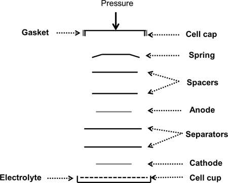
- Figure 2 shows a schematic of the coin cell assembly.
- Punch Celgard C480 membranes into discs of 19 mm in diameter and use them as separators.
- Transfer coin cell cases (CR2032), springs and spacers (purchased from MTI Corp.), separators and working electrodes into the glove box (after flushing the exchanger five times with argon).
- Assemble the coin cells in the glove box.
- Add two drops of the electrolyte on to the cell cup and place the working electrode on it. Add another three drops of the electrolyte and place two separators with two drops of electrolyte between them. Add two more drops of the electrolyte before placing the lithium counter electrode on it. Place two stainless steel spacers and a spring on the lithium disc.
- Close the cell using the cell cap and crimp 3-4 times using the compact crimping machine (purchased from MTI Corp.).
- After assembling the cells, handle the finished cells using plastic tweezers (to avoid short-circuiting).
- Clean the excess electrolyte leaking from the sides of the cell using a paper napkin.
- The cell is ready for testing and can be taken out of the glovebox.
5. Coin Cell Testing
- Keep the coin cell connected to the battery tester in the open circuit voltage (OCV) mode for one hour as soon as it is ready.
- Define voltage window for testing the cell based on the active material used in working electrode.
- Calculate the theoretical capacity for the cell using the calculations shown below.
Weight of the electrode disc with the current collector =WEO
Weight of the uncoated current collector disc of the same diameter =WCC
Weight of electrode material, WEM, is given by

Weight of active material in the electrode, WAM, is given by

Theoretical capacity for the electrode disc, CED, is given by

where C is the theoretical specific capacity of the active material.
- Test the coin cell to charge-discharge cycles at the required C-rate.
6. Representative Results
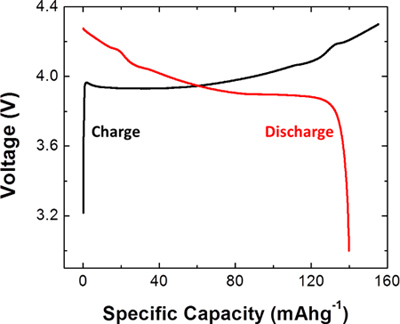
As an example, a coin cell was constructed using LiCoO2 as the active material for the working electrode. After construction, the cell was tested at C/5 rate. The obtained profile is shown in Figure 3. The voltage window was set to be between 3 and 4.3 V for this coin cell. The capacity was 155 mAh/g for the first charge cycle and 140 mAh/g for the first discharge cycle.

Figure 1. Flow chart of the coin cell construction procedure. First, a working electrode is prepared from the powder of the active material. Then, a counter electrode is prepared from a clean lithium foil and the separators are punched out. Finally, a cell is assembled inside an argon glovebox.

Figure 2. Schematic of a coin cell assembly process showing all the components in the order that they are placed inside the coin cell case.

Figure 3. Representative results obtained from a coin cell constructed using a working electrode made from LiCoO2 and a lithium foil counter electrode. The plot shows the first charge and first discharge curves for the coin cell that was charged and discharged at C/5 rate.

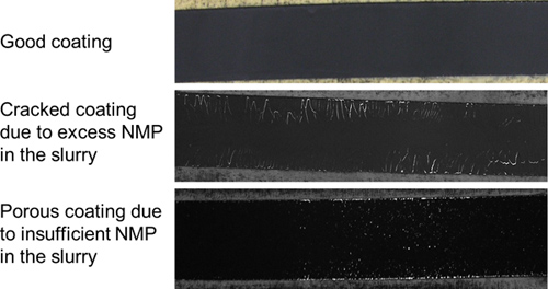
Figure 4. Comparison of good and bad coatings after they have been dried. A cracked coating typically results from slurry that has excess NMP and a porous coating typically results from slurry that has insufficient NMP.

Figure 5. Comparison of a well crimped coin cell and a badly crimped coin cell, along with an un-crimped cell. Typically, a badly crimped coin cell splits open after a few hours in ambient due to the swelling of lithium foil after reaction with moisture.
Access restricted. Please log in or start a trial to view this content.
Dyskusje
In our experience, the most critical step in the preparation of the working electrode is making good slurries with consistency. As shown in Figure 4, excess NMP in the slurry can result in a cracked coating, while insufficient NMP can result in a porous coating. In the work presented here, CR2032 coin cell cases that are 20 mm in diameter are used. It should be noted that coin cell cases of different sizes can be used, where the electrode sizes should be varied accordingly. During cell assembly, the appr...
Access restricted. Please log in or start a trial to view this content.
Ujawnienia
No conflicts of interest declared.
Podziękowania
We gratefully acknowledge the support from the Ceramics program in Division of Materials Research of the U.S. National Science Foundation, under the grant no. DMR-1006515 (program manager, Dr. Lynnette D. Madsen).
Access restricted. Please log in or start a trial to view this content.
Materiały
| Name | Company | Catalog Number | Comments |
| Poly(vinylidene fluoride) | Sigma-Aldrich | 182702 | |
| 1-Methyl-2-pyrrolidinone, 99.5% | Alfa Aesar | 31903 | |
| LiCoO2 | Alfa Aesar | 42090 | |
| Carbon black, acetylene, 99.9+% | Alfa Aesar | 39724 | |
| LiPF6 in EC:DMC:DEC | MTI Corporation | EQ-Be-LiPF6 | |
| Celgard separator | Celgard | C480 | |
| Analog Vortex Mixer | VWR | 58816-121 | |
| Vacuum oven | |||
| Vacuum pump | |||
| Hydraulic press | |||
| Coin cell case | MTI Corporation | EQ-CR2032-CASE-304 | |
| Spring and spacer | MTI Corporation | EQ-CR20SprSpa-304 | |
| Glovebox | mBraun | UNILAB | |
| Battery tester | Arbin Instruments | BT2143 |
Odniesienia
- Cairns, E. J., Albertus, P. Batteries for Electric and Hybrid-Electric Vehicles. Annual Review of Chemical and Biomolecular Engineering. 1, 299-320 (2010).
- Dunn, B., Kamath, H., Tarascon, J. -M. Electrical Energy Storage for the Grid: A Battery of Choices. Science. 334, 928-935 (2011).
- Goodenough, J. B. Cathode materials: A personal perspective. J. Power Sources. 174, 996-1000 (2007).
- Yamada, A., Chung, S. C., Hinokuma, K. Optimized LiFePO4 for lithium battery cathodes. Journal of the Electrochemical Society. 148, A224-A229 (2001).
- Whittingham, M. S. Lithium batteries and cathode materials. Chemical Reviews. 104, 4271-4301 (2004).
- Tarascon, J. M., Armand, M. Issues and challenges facing rechargeable lithium batteries. Nature. 414, 359-367 (2001).
- Goodenough, J. B., Kim, Y. Challenges for Rechargeable Li Batteries. Chemical Materials. 22, 587-603 (2010).
- Ceder, G. Identification of cathode materials for lithium batteries guided by first-principles calculations. Nature. 392, 694-696 (1998).
- Chung, S. Y., Bloking, J. T., Chiang, Y. M. Electronically conductive phospho-olivines as lithium storage electrodes. Nature Materials. 1, 123-128 (2002).
- Bruce, P. G., Scrosati, B., Tarascon, J. M. Nanomaterials for rechargeable lithium batteries. Angewandte Chemie-International Edition. 47, 2930-2946 (2008).
- Arico, A. S., Bruce, P., Scrosati, B., Tarascon, J. M., Van Schalkwijk, W. Nanostructured materials for advanced energy conversion and storage devices. Nature Materials. 4, 366-377 (2005).
- Hochbaum, A. I., Yang, P. D. Semiconductor Nanowires for Energy Conversion. Chemical Reviews. 110, 527-546 (2010).
- Wang, Y., Cao, G. Z. Developments in nanostructured cathode materials for high-performance lithium-ion batteries. Advanced Materials. 20, 2251-2269 (2008).
- Kang, B., Ceder, G. Battery materials for ultrafast charging and discharging. Nature. 458, 190-193 (2009).
- Liu, J., Manthiram, A. Improved Electrochemical Performance of the 5 V Spinel Cathode LiMn1.5Ni0.42Zn0.08O4 by Surface Modification. Journal of the Electrochemical Society. 156, A66-A72 (2009).
- Kayyar, A., Qian, H. J., Luo, J. Surface adsorption and disordering in LiFePO4 based battery cathodes. Applied Physics Letters. 95, (2009).
- Sun, K., Dillon, S. J. A mechanism for the improved rate capability of cathodes by lithium phosphate surficial films. Electrochemistry Communications. 13, 200-202 (2011).
- Kovalenko, I. A Major Constituent of Brown Algae for Use in High-Capacity Li-Ion Batteries. Science. 333, 75-79 (2011).
Access restricted. Please log in or start a trial to view this content.
Przedruki i uprawnienia
Zapytaj o uprawnienia na użycie tekstu lub obrazów z tego artykułu JoVE
Zapytaj o uprawnieniaPrzeglądaj więcej artyków
This article has been published
Video Coming Soon
Copyright © 2025 MyJoVE Corporation. Wszelkie prawa zastrzeżone