Single Crystal and Powder X-ray Diffraction
Overview
Source: Tamara M. Powers, Department of Chemistry, Texas A&M University
X-ray crystallography is a technique that uses X-rays to study the structure of molecules. X-ray diffraction (XRD) experiments are routinely carried out with either single-crystal or powdered samples.
Single-crystal XRD:
Single-crystal XRD allows for absolute structure determination. With single-crystal XRD data, the exact atomic positions can be observed, and thus bond lengths and angles can be determined. This technique provides the structure within a single crystal, which does not necessarily represent the bulk of the material. Therefore, additional bulk characterization methods must be utilized to prove the identity and purity of a compound.
Powder XRD:
Unlike single-crystal XRD, powder XRD looks at a large sample of polycrystalline material and therefore is considered a bulk characterization technique. The powder pattern is considered a "fingerprint" for a given material; it provides information about the phase (polymorph) and crystallinity of the material. Typically, powder XRD is used to study minerals, zeolites, metal-organic frameworks (MOFs), and other extended solids. Powder XRD can also be used to establish bulk purity of molecular species.
Previously, we have seen how to grow X-ray quality crystals (see video in Essentials of Organic Chemistry series). Here we will learn the principles behind XRD. We will then collect both single-crystal and powder data on Mo2(ArNC(H)NAr)4, where Ar = p-MeOC6H5.
Principles
Why X-rays?:
When measuring distance, it is important to select a unit of measure that is on the scale of the object being measured. For example, to measure the length of a pencil, one would not want to use a yard stick that only has feet gradations. Similarly, if one wanted to measure the length of a car, it would be inappropriate to use a 12-inch ruler with cm marks. Therefore, in order to study bonds in molecules, it is important to use a wavelength of light that matches the length of those bonds. X-rays have wavelengths in the Å range, which matches perfectly with typical bond distances (1-3 Å).
The Unit Cell:
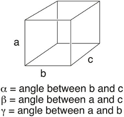
Imagine trying to describe all of the molecules on the tip of a pen. If one approximates that it's comprised of 6.02 × 10²³ molecules (or 1 mole), it would seem nearly impossible to describe that object on the molecular level. The complexity of an object is simplified when it exists as a crystal, where the contents of a unit cell can be used to describe the entire structure. The unit cell of a crystal is the least volume containing a repeating unit of a solid. It is defined as a 3D "box" with lengths a, b, and c, and angles α, β, and γ (Figure 1). The unit cell allows chemists to describe the contents of a crystal using a fraction of or a small number of atoms or molecule(s). By repeating the unit cell in space, one can generate a 3D representation of the solid.

Figure 1. Unit cell parameters.
Experimental Setup:
Single-crystal and powder XRD have similar instrumentation setups. For single-crystal XRD, a crystal is mounted and centered within the X-ray beam. For powder XRD, a polycrystalline sample is ground into a fine powder and mounted on a plate. The sample (single- or polycrystalline) is irradiated with X-rays and the diffracted X-rays hit a detector. During data collection, the sample is rotated with respect to the X-ray source and detector.
Double-slit Experiment:
Recall that light has both wave- and particle-like properties. When monochromatic light enters two slits, the wave-like property of light results in light emanating in a spherical fashion from each slit. When the waves interact, they can add together (if the waves have the same wavelength and phase) or cancel each other out (if the waves have the same wavelength, but have different phases), which is called constructive and destructive interference, respectively. The resulting light pattern is made of a series of lines, where the light areas represent constructive interference while the dark areas are a result of destructive interference.
Typical Diffraction Patterns: Single-crystal Versus Powder:
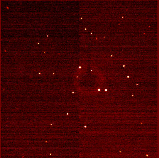
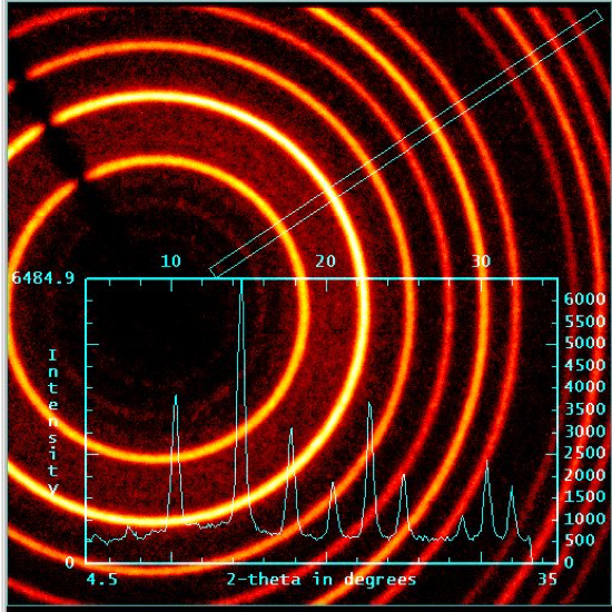
Upon irradiation of a crystal by X-rays, the radiation is diffracted upon interaction with electron density within the crystal. Just like water waves in the classic double-slit experiment from physics, the diffracted X-rays interact, resulting in constructive and destructive interference. In XRD, the diffraction pattern represents the electron density due to atoms and bonds within the crystal. A typical diffraction pattern for a single crystal is shown in (Figure 2). Notice that the diffraction pattern is comprised of spots instead of lines like in the double slit experiment. In fact, these “spots” are 2D slices of 3-dimensional spheres. Crystallographers use a computer program to integrate the resulting spots in order to determine the shape and intensity of the diffracted X-rays. In a powder sample, the X-rays interact with many tiny crystals in random orientations. Therefore, instead of seeing spots, a circular diffraction pattern is observed (Figure 3). The intensities of the diffracted circles are then plotted against the angles between the ring the beam axis (denoted 2θ) to give a 2 dimensional plot known as a powder pattern.
Here, we will collect single crystal and powder XRD data on Mo2(ArNC(H)NAr)4 where Ar = p-MeOC6H5, which was synthesized in the module “Preparation and Characterization of a Quadruply Metal–Metal Bonded Compound.”

Figure 2. Single Crystal Diffraction Pattern.

Figure 3. Powder XRD: Circular Diffraction Pattern.
Procedure
1. Collecting Single Crystal XRD Data
- Grow suitable crystals for XRD. For more information, please see videos "Growing Crystals for X-ray Diffraction Analysis" in the Essentials of Organic Chemistry series and "Preparation and Characterization of a Quadruply Metal-Metal Bonded Compound" in the Inorganic Chemistry series.
- Add a drop of paratone oil to a glass slide. Using a spatula and a small amount of paratone oil, scoop some crystals from the vial used to grow the crystals and add them to the drop of oil on the slide.
- Under a microscope, select a crystal that has uniform, well-defined edges.
- Pick up the selected crystal using a suitable mount (here we use a Kapton loop). Make sure that there that any oil stuck to the crystal is minimal once it is mounted.
- Open the instrument doors.
- Attach the mount to the goniometer head on the instrument.
- Center the crystal with respect to the location of the X-ray beam.
- Close the instrument doors.
- Open the APEX3 software suite, a graphical user interface (GUI) for X-ray crystallography.
- Run a short data collection sequence and determine the unit cell.
- Based on the unit cell data, pick a data collection strategy and run a full data collection.
- Workup the data using a suitable program. Here we use SHELX in the APEX 3 suite.
- Refine the structure in a suitable GUI. Here we use SHELX in OLEX2.
2. Loading a Powder Sample onto the Sample Holder for Powder XRD
NOTE: Here we will use a Si crystal zero background holder. There are a variety of alternate sample holders that can accommodate different amounts of material. The Si crystal zero background holder produces no background noise from 20-120 ° (2 θ, using Cu radiation).
- Place a fine mesh sieve above the Si crystal.
- Pour approximately 20 mg of the sample onto the sieve, making sure that most of the sample is directly above the Si crystal on the mount.
- Tap the sieve on the bench top until a monolayer of sample covers the Si crystal surface.
- Unscrew the sample holder and place the crystal in the holder.
3. Collecting a Powder XRD Pattern
- Open the instrument doors.
- Mount the sample holder in the instrument.
- Open the Commander software suite (a program used to collect powder XRD patterns).
- In the "Wizard" tab, load a standard data collection scan.
- Select the amount of time to run the scan (20 min). Running a longer scan over the same angle range will generate a better resolved powder XRD pattern.
- Select the angle range (2 θ) that will be scanned (5-70 °). The angle range selected depends on the material. The wavelength range given here is appropriate for molecular inorganic materials.
- Hit the "start" button to start data collection.
Results

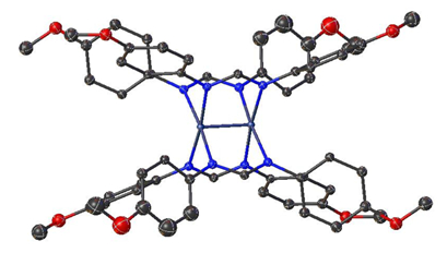
Figure 4. Single-crystal structure of Mo2(ArNC(H)NAr)4 where Ar = p-MeOC6H5.

Figure 5. Powder XRD pattern of Mo2(ArNC(H)NAr)4 where Ar = p-MeOC6H5.
Application and Summary
In this video, we learned about the difference between single-crystal and powder XRD. We collected both single-crystal and powder data on Mo2(ArNC(H)NAr)4, where Ar = p-MeOC6H5.
Single-crystal XRD is a powerful characterization technique that can provide the absolute structure of a molecule. While structure determination is the most common reason chemists use XRD, there are a variety of special X-ray techniques, such as anomalous scattering and photocrystallography, which provide more information about a molecule.
Anomalous scattering can distinguish between atoms of similar molecular weights. This technique is particularly valuable for characterization of heteropolynuclear metal complexes (compounds that have more than one metal atom with different identities). Anomalous scattering has also been used in protein crystallography as a method to help resolve the phase of the diffracted beam, which is important for structure determination.
Photocrystallography involves single-crystal XRD coupled to photochemistry. By irradiating a sample with light in the solid state, we can observe small structural changes and monitor those changes by XRD. Examples of this technique include observing isomerization of a molecule by light as well as characterization of reactive intermediates.
Powder XRD is a non-destructive characterization method that can be used to gain information about the crystallinity of a sample. In addition, it is a useful technique to analyze mixtures of different materials. As previously mentioned, powder patterns are like fingerprints: the resulting pattern of a compound is dependent on how the atoms are arranged within the material. Therefore, an experimentally-determined powder pattern can be compared to a collection of known diffraction patterns of materials in the International Centre for Diffraction Data. This not only provides information about the identity of the product isolated, but also allows scientists to comment on the number of compounds present in the sample. While a majority of the diffraction patterns listed in the database are in the family of extended solids such as minerals and zeolites, examples of inorganic molecules can be found.
Skip to...
Videos from this collection:

Now Playing
Single Crystal and Powder X-ray Diffraction
Inorganic Chemistry
105.2K Views

Synthesis Of A Ti(III) Metallocene Using Schlenk Line Technique
Inorganic Chemistry
31.7K Views

Glovebox and Impurity Sensors
Inorganic Chemistry
18.7K Views

Purification of Ferrocene by Sublimation
Inorganic Chemistry
54.7K Views

The Evans Method
Inorganic Chemistry
68.7K Views

Electron Paramagnetic Resonance (EPR) Spectroscopy
Inorganic Chemistry
25.6K Views

Mössbauer Spectroscopy
Inorganic Chemistry
22.0K Views

Lewis Acid-Base Interaction in Ph3P-BH3
Inorganic Chemistry
39.0K Views

Structure Of Ferrocene
Inorganic Chemistry
79.8K Views

Application of Group Theory to IR Spectroscopy
Inorganic Chemistry
45.9K Views

Molecular Orbital (MO) Theory
Inorganic Chemistry
35.5K Views

Quadruply Metal-Metal Bonded Paddlewheels
Inorganic Chemistry
15.3K Views

Dye-sensitized Solar Cells
Inorganic Chemistry
16.0K Views

Synthesis of an Oxygen-Carrying Cobalt(II) Complex
Inorganic Chemistry
51.8K Views

Photochemical Initiation Of Radical Polymerization Reactions
Inorganic Chemistry
17.1K Views
Copyright © 2025 MyJoVE Corporation. All rights reserved