Electrochemical Measurements of Supported Catalysts Using a Potentiostat/Galvanostat

Overview

Source: Laboratory of Dr. Yuriy Román — Massachusetts Institute of Technology

A potentiostat/galvanostat (often referred to as simply a potentiostat) is an instrument that measures current at an applied potential (potentiostatic operation) or measures potential at an applied current (galvanostatic operation) (Figure 1). It is the most commonly used instrument in the electrochemical characterization of anode and cathode materials for fuel cells, electrolyzers, batteries, and supercapacitors.

Conventionally, these anode and cathode materials are interfaced with a potentiostat via a three-electrode electrochemical cell. The electrode leads from the potentiostat are connected to the reference electrode, the counter electrode (often called the auxiliary electrode), and the working electrode (which contains the test material of interest). The electrochemical cell is then filled with a high ionic strength electrolyte solution, such as an acidic, alkaline, or salt solution. The media for this high ionic strength solution is typically aqueous; however, for applications necessitating higher operating cell potential windows, such as batteries and supercapacitors, non-aqueous media is often used. The cell media is degassed with an inert gas (to prevent unwanted side reactions) or with a test gas (if the test reaction involves a gas at one of the electrodes).

Alternatively, a salt bridge or membrane is employed to maintain ionic contact if the two half cells are to be measured in different electrolytes. In heterogeneous electrocatalysis, this type of "two compartment" cell is often used if the test molecule at the working electrode is also reactive at the counterelectrode. This happens frequently as the counterelectrode typically employed is platinum, which is a highly active catalyst for many reactions. Here, single compartment cells will be used, where all three electrodes are in the same media.

This video will explain the process of polishing a working electrode, preparing a catalyst ink, mounting the catalyst ink onto the working electrode, preparing the electrochemical cell, and then performing electrochemical measurements. The measurements that are performed include: cyclic voltammetry (CV), linear sweep voltammetry (LSV), chronopotentiometry (CP), and chronoamperometry (CA).

Figure 1
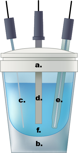
Figure 1. An example of a single compartment electrochemical cell. a.) Teflon cap, b.) glass cell, c.) Pt wire counter electrode, d.) working electrode, e.) Ag/AgCl reference electrode, f.) 0.5 M aqueous sulfuric acid electrolyte solution.

Principles

The potentiostat can be used to apply a constant anodic or cathode potential to the working electrode and measure the resulting anodic or cathodic current (chronoamperometry) or the potentiostat can be operated galvanostatically via a feedback control loop and apply a constant anodic or cathodic current with the measured potential varying with time to maintain this applied current (chronopotentiometry). Alternatively, potential space may be explored with time using cyclic voltammetry or linear sweep voltammetry to measure anodic and cathodic potentials versus an applied potential scan rate (the derivative of potential with respect to time).

In all of these techniques, even during galvanostatic operation, the potentiostat controls the applied potential and measures the flow of electrons from (to) the working electrode to (from) the counter electrode when the working electrode is acting as the anode (cathode). The applied potential is referenced against the reference electrode, which contains a redox system (such as a silver chloride electrode or saturated calomel electrode) with a known and stable potential that is interfaced with the electrolyte solution via a porous frit. During normal operation, the potentiostat draws a negligible but nonzero current through the reference electrode so that an accurate potential can be applied to the working electrode. While the potentiostat measures the flow of electrons to or from one half reaction to the next, the electrolyte solution completes the circuit by preventing charge buildup at either the anode or the cathode.

Procedure

1. Catalyst Ink and Working Electrode Preparation

Safety Precautions: Metals supported on carbon black must be handled in a fume hood or balance enclosure until it is in suspension form as these powders are inhalation hazards.

  1. Using an enclosed balance, weigh out 5–10 mg of metal/carbon black catalyst and add to a glass vial with a cap.
  2. Using a micropipette, dilute the catalyst with water such that the final concentration is 7.5 mg of catalyst per mL of water.
  3. While sonicating, 100 µL of Nafion 117 solution per mL of water is added to the suspension.
  4. The ink should be sonicated for at least 10 min to ensure uniform dispersion and complete mixing of the carbon black support with the binding agent.
  5. While the ink is sonicating, a 3 mm glassy carbon disk electrode should be cleaned and polished by rubbing it in a swirling circular motion on a soft alumina pad covered with 0.05 µm alumina solution. It should then be rinsed copiously with water to remove the alumina.
  6. Next, 7 µL of ink is dripped onto a polished, vertically-oriented 3 mm glassy carbon disk electrode. The working electrode is then dried at 80 ˚C for 1 h if the catalyst is air-stable or evaporated under a weak vacuum for 30 min if the catalyst is air-sensitive.

2. Electrochemical Cell Preparation

Safety Precautions: Gloves, labcoat, and safety glasses must always be worn but is especially paramount for working with the sulfuric acid solution. Should any drops of solution spill onto the wrists, it must be washed with soap and water for 15 min. For major spills, removal of contaminated garments and use of the eyewash or showers should be used for 15 min followed by a medical consultation. The electrical leads should not be touched once placed onto the electrochemical cell.

  1. A glass cell is filled with 10 mL of 0.5 M H2SO4 and degassed for at least 30 min with an ultra high purity nitrogen stream
  2. The Teflon caps of the electrochemical cells have 3 ports for the working electrode, counter electrode, and the reference electrode
  3. The Ag/AgCl reference electrode is removed from its 1 M KCl solution, rinsed thoroughly with DI water, and then placed into the cell.
  4. The platinized platinum wire counter electrode is rinsed thoroughly with DI water and then placed into the cell.
  5. The dried working electrode is rinsed with DI water and then placed into the cell.
  6. The potentiostat is turned on.
  7. The white electrode lead is connected first and connected to the reference electrode.
  8. The red electrode lead is then connected to the Pt wire counter electrode.
  9. The green electrode lead is then connected to the metal/carbon black working electrode.
  10. A small N2 purge stream is left continuously bubbling in the electrolyte.
  11. Ensure no leads are touching and that there is no direct electrical contact between the 3 electrodes other than with the 0.5 M H2SO4 electrolyte.

3. Electrochemical Analysis

  1. After turning on the potentiostat, perform at least 20 conditioning cycles between 0 and 0.4 V vs. RHE at 50 mV/s using CV. This is performed by choosing CV as a technique and entering the upper and lower potential limits as well as the scan rate.
  2. Linear Sweep Voltammetry (LSV) can then be performed by choosing LSV as a technique and specifying a starting potential, a final potential, and a scan rate. The scan rate for LSV is typically much less than CV, usually 1 – 2 mV/s so that capacitive currents become much lower than currents arising from faradaic surface reactions
  3. Chronoamperometry (CA) is performed by choosing CA or "Amperometric i-t curve" as a technique and specifying the fixed potential as well as the length of time the instrument should hold the working electrode as this fixed potential.
  4. Chronopotentiometry (CP) is performed by choosing CP as a technique. CP can be performed in a series of current steps where one current is specified for a certain length of time followed by a new current for a specified length of time. These applied currents can span both anodic and cathodic currents within the same CP measurement.
  5. When the electrochemical analysis is finished, turn off the potentiostat.
  6. Disconnect the electrode leads and store them in a dry place away from any liquids to prevent corrosion.
  7. Remove the reference electrode and rinse with copious amounts of DI water. Then return the reference electrode directly to its 1 M KCl storage solution. The tip of this electrode should never be allowed to become dry.
  8. Remove the Pt wire counter electrode and rinse thoroughly with DI water
  9. Remove the working electrode and rinse thoroughly with DI water and then use a Kimwipe with acetone to easily remove the dried catalyst ink from the working electrode surface. It is recommended to polish electrodes immediately after use.
  10. Turn off the N2 purge.
  11. Empty the used electrolyte into an acidic waste container. Rinse the glass cell and Teflon cap with copious amounts of DI water.
Results

This procedure will result in figures containing plots of measured current vs. potential for each of the four techniques. By convention for CV and LSV, the plots will also be outputted as measured current vs. potential despite the reality that these are transient techniques that measure current vs. the time derivative of potential.

Application and Summary

CV, LSV, CP, and CA are indispensable techniques for determining the efficacy of new electrode materials for fuel cells, electrolyzers, batteries, and supercapacitors as well as for developing fields such as the selective partial oxidation or reduction of commodity chemicals. These methods allow for determining overpotentials of reactions on different electrode materials as compared to their thermodynamic equilibrium potentials. These methods also allow the volumetric or gravimetric capacitance of supercapacitors to be determined. Similarly, rates of charging/discharging of battery electrodes or supercapacitors can be determined with these techniques. These techniques also allow for the characterization of the electrochemical stability of the materials to be determined. Beyond these basic techniques, more advanced techniques include the combination of potentiometric techniques with in-situ methods such as IR and mass spectrometry.

Tags
Electrochemical MeasurementsSupported CatalystsPotentiostatGalvanostatElectrochemical CharacterizationElectrical ChangesRedox ReactionsOxidation reductionElectrode SurfaceTransfer Of ElectronsApplied PotentialThree electrode CellWorking ElectrodeCounter ElectrodeReference Electrode

Skip to...

0:00

Overview

1:09

Principles of Voltammetry

4:36

Working Electrode Preparation

5:51

Electrochemical Cell Preparation

6:53

Electrochemical Analysis

8:38

Applications

10:17

Summary

Videos from this collection:

article

Now Playing

Electrochemical Measurements of Supported Catalysts Using a Potentiostat/Galvanostat

Analytical Chemistry

51.1K Views

article

Sample Preparation for Analytical Characterization

Analytical Chemistry

83.0K Views

article

Internal Standards

Analytical Chemistry

202.8K Views

article

Method of Standard Addition

Analytical Chemistry

318.2K Views

article

Calibration Curves

Analytical Chemistry

787.3K Views

article

Ultraviolet-Visible (UV-Vis) Spectroscopy

Analytical Chemistry

614.6K Views

article

Raman Spectroscopy for Chemical Analysis

Analytical Chemistry

50.5K Views

article

X-ray Fluorescence (XRF)

Analytical Chemistry

25.2K Views

article

Gas Chromatography (GC) with Flame-Ionization Detection

Analytical Chemistry

279.0K Views

article

High-Performance Liquid Chromatography (HPLC)

Analytical Chemistry

380.3K Views

article

Ion-Exchange Chromatography

Analytical Chemistry

262.4K Views

article

Capillary Electrophoresis (CE)

Analytical Chemistry

92.7K Views

article

Introduction to Mass Spectrometry

Analytical Chemistry

110.9K Views

article

Scanning Electron Microscopy (SEM)

Analytical Chemistry

86.3K Views

article

Cyclic Voltammetry (CV)

Analytical Chemistry

122.9K Views

JoVE Logo

Privacy

Terms of Use

Policies

Research

Education

ABOUT JoVE

Copyright © 2025 MyJoVE Corporation. All rights reserved