
このコンテンツを視聴するには、JoVE 購読が必要です。 サインイン又は無料トライアルを申し込む。
Method Article
マイクロ管状火炎補助燃料電池用燃焼特性とモデル燃料開発
要約
A protocol for creating a model fuel-rich combustion exhaust is developed through combustion characterization and is applied for micro-tubular flame-assisted fuel cell testing and research.
要約
Combustion based power generation has been accomplished for many years through a number of heat engine systems. Recently, a move towards small scale power generation and micro combustion as well as development in fuel cell research has created new means of power generation that combine solid oxide fuel cells with open flames and combustion exhaust. Instead of relying upon the heat of combustion, these solid oxide fuel cell systems rely on reforming of the fuel via combustion to generate syngas for electrochemical power generation. Procedures were developed to assess the combustion by-products under a wide range of conditions. While theoretical and computational procedures have been developed for assessing fuel-rich combustion exhaust in these applications, experimental techniques have also emerged. The experimental procedures often rely upon a gas chromatograph or mass spectrometer analysis of the flame and exhaust to assess the combustion process as a fuel reformer and means of heat generation. The experimental techniques developed in these areas have been applied anew for the development of the micro-tubular flame-assisted fuel cell. The protocol discussed in this work builds on past techniques to specify a procedure for characterizing fuel-rich combustion exhaust and developing a model fuel-rich combustion exhaust for use in flame-assisted fuel cell testing. The development of the procedure and its applications and limitations are discussed.
概要
技術が発展し続けている固体酸化物形燃料電池(SOFC)の技術革新は、近年報告されています。多くの利点の中で、SOFCのは、他の燃焼ベースの発電技術1に比べて低燃費、低排出ガスと適度な燃料柔軟性のために知られるようになりました。また、SOFCのは、小さなスケールで高い燃料効率を可能にするスケーラブルです。残念ながら、現在の水素インフラの制限は、多くの場合、非効率的である燃料改質システムの必要性を作成しました。最近の開発は、著者の前作2で報告されたマイクロ管状火炎補助燃料電池(MT-FFC)です。 MT-FFC燃焼3を介して改質発熱及び燃料を提供し、元の直接火炎型燃料電池(DFFC)の利点に基づいて構築火炎補助燃料電池(FFC)の最初の例です。 DFFCのセットアップは、周囲ENVIRに開放炎と直接接触してSOFCを配置しますonment。火炎は、部分的に純粋なメタンまたは他の重質炭化水素に比べて炭素コークス化にはあまり可能性を有するSOFCに直接使用することができるH 2およびCOを生成するために、より重い炭化水素燃料を酸化します。また、火炎がその動作温度にSOFCをもたらすために必要な熱エネルギーを提供します。元DFFCへの最近の変更は、火炎領域のうち、SOFCを移動し、FFC 2を作成するために、SOFCに燃焼排気をチャネリングすることによって発生しました。空気比に対して燃料を制御することができ、排気が直接完全燃焼が発生することなく、燃料電池に供給することができるようにDFFC異なり、燃焼が(代わりに、周囲の)部分的に囲まれたチャンバー内で起こります。 FFCはDFFCs 2と比較して高い燃料利用率と高い電気効率などの追加の利点を有しています。
研究の新興分野としては、必要とされている実験技術MT-FFの可能性を評価することができ将来の発電用途のためにCS。これらの技術は、CO 2とH 2 Oと一緒に、部分酸化、又は燃料リッチ燃焼、及びまた合成ガスとして知られているH 2およびCOを生成する方法として同定された排気ガスの分析を必要とします合成ガスは、発電用燃料電池に直接使用することができます。燃料リッチ燃焼排ガスの分析はよく近年確立され、多くの異なる目的のために、理論的に4、計算5,6及び実験7行われています。理論および計算の研究の多くは、反応機構のための燃焼生成物のエネルギー的に有利な種、および反応速度論モデルを評価するために、化学平衡分析(CEA)に依存していました。これらのメソッドは非常に有用であったが、多くの新興技術が研究開発中に実験技術に依存してきました。実験技術は、典型的には、アナに依存しますガスクロマトグラフ(GC)7または質量分析計(MS)のいずれかを使用して燃焼排ガスの溶解8。 GC線/注射器またはMSプローブのいずれかは、燃焼排ガス中に挿入され、測定値は、種の濃度を評価するために取られます。実験技術の適用は、小規模発電の分野で一般的でした。いくつかの例は、シングルチャンバ型SOFC 7,9及びDFFCs 10~15で動作するように開発されてきたマイクロ燃焼器を含みます。燃焼排ガスの分析は、異なる温度、流量および当量比を含む広範囲の動作条件の下で起こります。
DFFC研究の分野では、燃料と酸化剤は、完全燃焼を確実に周囲に開放バーナーで、部分的に予混合または非予混合することができます。火炎の組成を分析する必要性と、MSはDFFC研究および燃焼分析16のために多くの例で使用されています。 FFCのより最近の開発は、燃料の完全酸化を防止するために、部分的に囲まれた環境でバーナーで予混合燃焼に頼ることによって異なります。その結果、空気漏れのない制御された環境での燃焼排ガスの分析が必要とされています。この目的のために開発された実験技術は、様々な当量比での燃焼排気のGC分析とマイクロ燃焼器の研究のために使用される以前の技術に依存しています。 GC分析は、燃焼排ガス組成物の特性をもたらす( すなわち 、CO 2を含む各排気成分の体積%、H 2 O、N 2 等 )この分析は、によって測定比に従って別個のガスの混合を可能にしますGCは将来のFFCの研究のためのモデル燃料リッチ燃焼排気を作成します。
、燃料リッチ燃焼排ガスを分析するモデルの燃料リッチ燃焼排気を開発し、適用するためのプロトコルSOFCのテストのために排気をるが、本論文で確立されています。共通の課題と制限は、これらの技術のために議論されています。
プロトコル
1.燃焼計算
- 分析のための燃料を選択します。ここで、基準燃料としてメタンを選択しますが、原則は、他の炭化水素燃料に譲渡することはできません。
- ストイキ燃焼用の燃料としてメタン1モル、バランス式(1)で式を取得する(2)。


- 空気の質量によってメタンの質量を除することにより、化学量論のための燃空比(F / ストイキ。)メタン燃焼のための式(3)のように計算します。計算するために、分子は、メタン倍のモル数のメタンのモル質量(15・Gモル-1)であり、分母は、酸素倍のモル数の酸素のモル質量(32・Gモル-1)プラス窒素倍のモル数の窒素のモル質量(29・Gモル-1)。

- 当量比(式4)を変化させるために、空気流量、燃料流量、または同時に両方を変化させます。一般的に、数量の1を固定し、他を変えます。バーナー用の燃料や空気流量のいずれかを修正するかどうかを決定します。この実験では、10 L /分で燃料流量を固定し、空気流量がこの設定で変化することを可能にします。

- 固定された燃料流量、F、(10L /分)、F / ストイック有します。計算された(0.0583)、および当量比の定義が与えられ、空気流量を算出し、試験すべきそれぞれの当量比のために。式(5)それぞれの当量比はL /分の空気流量を計算する直接的な方法を提供し、その結果を化学量論は1の当量比について示されています。

注:上部フラム能力制限(または上爆発限界)は、触媒の非存在下で火炎を消光することなく燃焼させることができる豊かな当量比です。高い当量比は、触媒の使用を得ることができるが、唯一の非触媒燃焼は、この論文に記載されています。選択された燃料の上限可燃限界を評価するための文献を参照してください。
2.燃焼特性評価実験のセットアップ
- ステップ1.5で得られた流量に基づいて、メタンと空気のためのマスフローコントローラ(MFCの)を選択します。テスト中にMFCがその範囲のローエンドで動作されないことを確実にするために(フルスケール値の<10%)をMFCのサイズを選択するときは注意してください。この特定のケースでは、それぞれ、メタンと空気を40リットル/分および200リットル/分のMFCを使用します。
- 銅管を経由してメタンと空気タンクにマスフローコントローラを接続します。
- 指定されているMFCのための適切な圧力にメタンと空気タンク上のレギュレータを設定メーカーによります。この場合、138キロパスカル(20 PSI)に圧力を設定します。
- 正確な流量を確保するためのMFCを校正。
- 燃焼室を構築します。この実験では、燃焼室168ミリメートル出口直径と長914ミリ開発します。
- 燃焼室の長さに沿って燃焼排ガス分析および熱電対の配置のためのポートをドリル。必要な正確な数と間隔は、炎の大きさと実験の目的に依存します。この設定の場合、空間最初の5の熱電対は、7ミリメートル離れて燃焼領域に最も近いを置きました。スペース最終6熱電対離れて14ミリメートル。排気ポートに同じ間隔を使用してください。
- ポートホールを介して燃焼室にK型熱電対を挿入します。燃焼室の中央に熱電対の先端を合わせます。サイズポート孔は、熱電対にフィットし、高温金属フェルールと漏れを防止するナットでシールします。
- コンECTデータ収集モジュールに直接的にK型熱電対。
- USBドライブを介してコンピュータにデータ取得モジュールを接続します。
- 直ちに燃料MFC後、ちょうどバーナーの前に銅管路内の一方向弁を取り付けます。オリエントその流れがMFCから離れることができるようにバルブ。一方向弁は、フラッシュバックを防止するための安全上重要な機能です。
- 漏れがないMFCのセットアップの前と後の銅管を確認してください。漏れが泡を作ると同じようにリークを検出するために、チューブにブラシで適用される石鹸水を使用してください。
- 銅管を介してマスフローコントローラに燃焼室と、バーナーを接続します。
- 燃焼室のセットアップが完了した後、試験用の排気ポートのいずれかを選択します。 GC分析ポートに拡張する銅管にこのポートを接続します。
- 燃焼室から排気を引き出し、その後、分析のためのGCにそれをプッシュするために注射器を選択します。この実験では、使用25mlのシリンジ。
- GCに排気ポートを接続する銅管に沿って三方弁を配置します。 GC、排気口に第25ミリリットル注射器に第三に二方弁の一方の端を接続します。 3ウェイバルブに銅管を接続します。室からの燃焼排ガスを吸うし、その後の分析のためのGCにそれをプッシュするために注射器を使用してください。
- GCおよび注射器に3方向バルブを接続してください。正常な動作を保証するために、シリンジプランジャを作動させます。
注:設定の簡略図を図1に示されています。

図1.燃焼特性評価実験の概略図。燃焼特性評価実験を示す概略図燃料、空気及び排気の流れ(黒矢印)と、データ・フロー(赤い矢印)。一方向弁は、フラッシュバックを防ぐために使用されます。 この図の拡大版をご覧になるにはこちらをクリックしてください。
3.燃焼特性評価実験
- 試験前に、完全にシリンジプランジャーを押すと排気口側の三方弁を開きます。
- 86.5リットル/分の流量に最初のエアMFCをオンにします。
- 10リットル/分の流量に上メタンMFCをオンにします。これは、発火しやすいです1.10の予混合当量比、少しリッチな混合物を作成します。
- 記録データを開始するために、コンピュータモジュールを介して熱電対をオンにします。
- ブタンライターを用いて燃焼室の端部に混合物を点火します。点火後、炎がバーナーフロントで安定する必要があります。
- 所望の値に86.5リットル/分の初期値から徐々に空気の流量を調整することにより、当量比を調整します。あまりにも速く移動またはflammabの外に出ないように注意してください消炎を引き起こすilityを制限します。
- 熱電対の温度が安定した後、データファイルを読み込む温度を記録します。
- もう一度、排気ポートから燃焼排気ガスを抽出するために、シリンジのプランジャーを引きます。
- 燃焼排ガスを抽出した後、GC側に三方弁を開いて排気口側を閉じます。
- それは完全に閉じ、排気のすべてがGCに送信されてきたまではシリンジプランジャを押してください。
- GCへのポートを接続する銅管の残留ガスの全てが除去されるまで繰り返して、3.8から3.10を繰り返します。注射器の容積に比べて銅管の内部容積の単純な分析が繰り返されるべき3.8から3.10の必要性をステップ回数を示します。
- チューブ内のすべての残留ガスを除去した後、分析のための最終的な排気サンプルを抽出します。 GCに排気ガスを押して、分析モード7,17にGCの電源を入れます。
- 保存することで、GCデータを記録GC分析データ。
- 全ての所望の当量比がテストされるまで繰り返し、3.1から3.13を繰り返します。
モデル燃焼排気の4開発
- トレンドを観察する燃焼排ガス種の体積分率をプロットします。
- モデル燃焼排気のためのカットオフ濃度値を決定します。初期MT-FFC分析のためのモデル燃焼排ガスを燃料の開発に、かなりの割合(> 1%)に現れるだけのコンポーネントがモデル燃料に含まれています。
- モデル燃料の排気が大幅に水素と一酸化炭素(各成分について> 1%)を生成のみ当量比を選択します。
- 4.3の条件を満たし、排気ガス成分のそれぞれの音量の割合を記録します。
5.燃料電池のテストのセットアップ
- 各ガスの流量範囲を決定します。 tでGC分析結果から得られる体積百分率を掛け彼は、各燃料電池内の所望のモデル燃焼排ガスの流量を合計します。
- それぞれの種のための最大および最小流量を決定するために各燃焼排ガス種に対する流量の範囲を評価します。
- ステップ2.1で説明したのと同じ原理に基づいて流量計を選択します。
- 銅管を介してガスのタンクに流量計を取り付けることにより、試験装置を構築します。
- 流量計のための規定値へのガスの圧力調整器を設定します。
- 可燃性ガスを使用して、各流量計の下流の銅管路内に一方向弁を配置します。
- 銅管とマニホールドを介して一緒にすべての流量計の出口ポートを接続します。
- 燃料電池の外径よりもわずかに大きい内径を有する鋼管の内側にマイクロチューブ状SOFCを設定します。セラミック接着剤を用いた鋼管の燃料電池をシールします。
- セラミック耐火メートルの片にマイクロチューブ状SOFCとスチールチューブを接続します炉内の燃料電池を保持するaterial。
- アノード上の2ワイヤとカソード上の2線を有するマイクロチューブ状SOFCに接続された電流収集および電圧センスワイヤで4プローブ法10,11を利用しています。ワイヤが互いに作成ショーツ交差しないことを確認してください。
- ポテンショスタット10,11の4つのプローブに4本のワイヤを接続します。
- コンピュータ10,11にポテンショスタットを接続します。
- マイクロチューブ状SOFC電解質10,11の外側に触れる先端で炉内に熱電対を配置します。
- データ取得モジュールに熱電対のワイヤを取り付けます。
- USBポートを介してコンピュータにデータ収集モジュールを接続します。
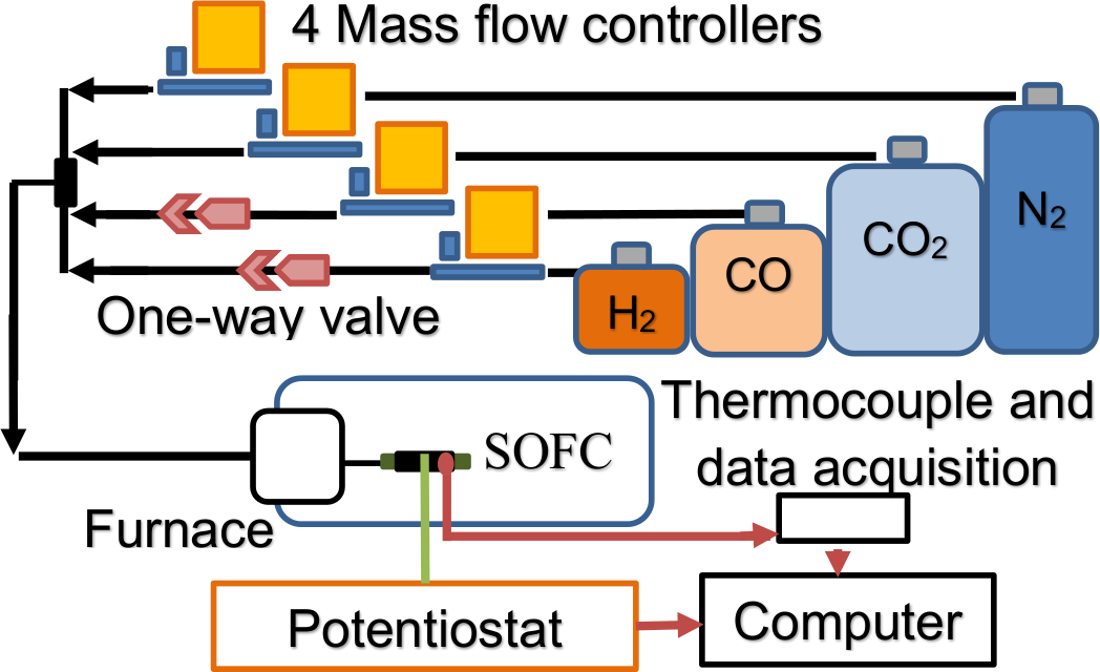
メモ: 図2は、MT-FFCテストのセットアップを簡略化して示す概略図です。開発されたモデルの燃料と燃料電池のモデル燃料の流れを制御するための確立された設定で、検査は、従来Fに従って進めることができますUEL細胞試験方法。これらの方法は、文献に十分に確立されており、ここでは繰り返しません。

図2マイクロ管状火炎補助燃料電池試験のセットアップ概略図でH 2、CO、CO 2の流れ、N 2(黒矢印)は、MFCとフラッシュバックを防止するための一方向弁で調節されます。バックSOFCへのポテンショスタットとする炉内のSOFCからの電子の流れ(緑線)。熱電対のデータおよび電気化学的データの流れは、赤い矢印で表されている。 この図の拡大版をご覧になるにはこちらをクリックしてください。
結果
燃焼特性評価室は試験中のチャンバまたは他の空気漏れへの空気の逆流のための所望の当量比で試験前にチェックする必要があります。開いたチャンバ内の燃焼プロセスはほぼ同重体であることが知られています。その結果、燃焼室内の圧力は、外部環境からの空気は、チャンバの排気ポートまたは他の漏電点から燃焼室内に逆流しないことを保証するのに十分では?...
ディスカッション
ここで説明するプロトコルは、前回の燃焼特性評価の研究と燃料電池試験の間の重要な橋です。燃料改質燃料電池試験用の燃焼の使用はDFFCセットアップ10-15に数年間適用されています。しかし、DFFCsにおける燃焼プロセスの特性は、火炎組成物16 のその場キャラクタリゼーションと主に関係しているとMS 8を使用しています。 DFFCが周囲に開放されている...
開示事項
The authors have nothing to disclose.
謝辞
This work is supported by an agreement with Syracuse University awarded by the Syracuse Center of Excellence in Energy and Environmental Systems with funding under prime award number DE-EE0006031 from the US Department of Energy and matching funding under award number 53367 from the New York State Energy Research and Development Authority (NYSERDA), contract 61736 from NYSERDA, and an award from Empire State Development's Division of Science, Technology and Innovation (NYSTAR) through the Syracuse Center of Excellence, under award number #C120183. This work is supported by the National Science Foundation Graduate Research Fellowship Program under Grant No. 1247399.
資料
| Name | Company | Catalog Number | Comments |
| Gas chromotograph | SRI Instruments, Inc. | SRI 8610C | |
| K type thermocouples | Omega | KQXL-116G-6 | Custom length |
| K type thermocouple extension wire | Omega | EXTT-K-20-SLE-100 | |
| Mass flow controller | Omega | FMA5427 | 0-40 L/min (N2) Used for methane |
| Mass flow controller | Omega | FMA5443 | 0-200 L/min (N2) Used for air |
| Mass flow controller | Omega | FMA5402A | 0-10 ml/min (N2) Used for CO |
| Mass flow controller | Brooks Instrument | SLA5850 | 200 SCCM (Propane) Used for CO2 |
| Mass flow controller | Brooks Instrument | SLA5850 | 5 L/min (Air) Used for N2 |
| Mass flow controller | Brooks Instrument | SLA5850 | 500 SCCM (N2) Used for H2 |
| Regulator | Harris Products Group | HP721-125-350-F | Methane tank |
| Regulator | Harris Products Group | HP702-050-590-E | Air tank |
| Regulator | Airgas | Y11-SR145B | CO tank |
| Regulator | Harris Products Group | HP702-050-320-E | CO2 tank |
| Regulator | Airgas | Y12-215B | N2 tank |
| Regulator | Harris Products Group | HP702-015-350-D | H2 tank |
| Methane, Compressed, Ultra high purity | Airgas | UN1971 | Extremely Flammable |
| Air, Compressed, Ultra pure | Airgas | UN1002 | Not classified as hazardous to health. |
| CO, Compressed, Ultra high purity | Airgas | UN1016 | Toxic by inhalation, Extremely flammable |
| CO2, Compressed, Research grade | Airgas | UN1013 | Asphyxiant in high concentrations |
| N2, Compressed, Ultra high purity | Airgas | UN1066 | Not classified as hazardous to health. |
| H2, Compressed, Ultra high purity | Airgas | UN1049 | Extremely flammable, burns with invisible flame |
| Source meter | Tektronix, Inc. | Keithley 2420 | Connects to computer via USB |
| Horizontal split tube furnace | MTI Corportation | OTF-1200X | |
| Data acquisition | National Instruments | NI cDAQ-9172 | Connects to computer via USB |
| Thermocouple input | National Instruments | NI 9211 | Connects to cDAQ-9172 |
| Computer control for Mass Flow Controllers | National Instruments | NI 9263 | Connects to cDAQ-9172 Computer control for Mass Flow Controllers |
| Testing software | National Instruments | LabVIEW 8.6 | |
| Ceramabond | Aremco | 552-VFG | 1 Pint |
参考文献
- Gorte, R. J. Recent developments towards commercialization of solid oxide fuel cells. AIChE J. 51 (9), 2377-2381 (2005).
- Milcarek, R. J., Wang, K., Falkenstein-Smith, R. L., Ahn, J. Micro-tubular flame-assisted fuel cells for micro-combined heat and power systems. J. Power Sources. 306, 148-151 (2016).
- Horiuchi, M., Suganuma, S., Watanabe, M. Electrochemical power generation directly from combustion flame of gases, liquids, and solids. J. Electrochem. Soc. 151 (9), A1402-A1405 (2004).
- Starik, A. M., Kuleshov, P. S., Loukhovitski, B. I., Titova, N. S. Theoretical study of partial oxidation of methane by non-equilibrium oxygen plasma to produce hydrogen rich syngas. Int. J. Hydrogen Energy. 40 (32), 9872-9884 (2015).
- Katta, V. R., et al. On flames established with jet in cross flow of fuel-rich combustion. Fuel. 150, 360-369 (2015).
- Maruta, K., et al. Extinction limits of catalytic combustion in microchannels. P. Combustion Institute. 29 (1), 957-963 (2002).
- Ahn, J., Eastwood, C., Sitzki, L., Ronney, P. D. Gas-phase and catalytic combustion in heat-recirculating burners. P. Combustion Institute. 30 (2), 2463-2472 (2005).
- Kӧhler, M., Oßwald, P., Xu, H., Kathrotia, T., Hasse, C. Speciation data for fuel-rich methane oxy-combustion and reforming under prototypical partial oxidation conditions. Chemical Engineering Science. 139, 249-260 (2016).
- Ahn, J., Ronney, P. D., Shao, Z., Haile, S. M. A thermally self-sustaining miniature solid oxide fuel cell. J. Fuel Cell Science and Technology. 6 (4), 041004 (2009).
- Wang, K., Milcarek, R. J., Zeng, P., Ahn, J. Flame-assisted fuel cells running methane. Int. J. Hydrogen Energy. 40 (13), 4659-4665 (2015).
- Wang, K., Zeng, P., Ahn, J. High performance direct flame fuel cell using a propane flame. P. Combust. Inst. 32 (2), 3431-3437 (2011).
- Wang, Y. Q., Shi, Y. X., Yu, X. K., Cai, N. S., Li, S. Q. Integration of solid oxide fuel cells with multi-element diffusion flame burners. J. Electochem. Soc. 160 (11), F1241-F1244 (2013).
- Horiuchi, M., et al. Performance of a solid oxide fuel cell couple operated via in situ catalytic partial oxidation of n-butane. J. Power Sources. 189 (2), 950-957 (2009).
- Wang, Y., et al. The study of portable direct-flame solid oxide fuel cell (DF-SOFC) stack with butane fuel. J. Fuel Chem. Technol. 42 (9), 1135-1139 (2014).
- Wang, K., et al. A high-performance no-chamber fuel cell operated on ethanol flame. J. Power Sources. 177 (1), 33-39 (2008).
- Sun, L., Hao, Y., Zhang, C., Ran, R., Shao, Z. Coking-free direct-methanol-flame fuel cell with traditional nickel-cermet anode. Int. J. Hydrogen Energy. 35 (15), 7971-7981 (2010).
- Zeng, P., Wang, K., Falkenstein-Smith, R. L., Ahn, J. Effects of sintering temperature on the performance of SrSc0.1Co0.9O3-δ oxygen semipermeable membrane. Braz. J. Chem. Eng. 32 (3), 757-765 (2015).
- Turns, S. R. . An Introduction to Combustion: Concepts and Applications. , (2000).
- Glassman, I., Yetter, R. A., Glumac, N. G. . Combustion. , (2015).
転載および許可
このJoVE論文のテキスト又は図を再利用するための許可を申請します
許可を申請さらに記事を探す
This article has been published
Video Coming Soon
Copyright © 2023 MyJoVE Corporation. All rights reserved