
Aby wyświetlić tę treść, wymagana jest subskrypcja JoVE. Zaloguj się lub rozpocznij bezpłatny okres próbny.
Method Article
Combustion Characterization and Model Fuel Development for Micro-tubular Flame-assisted Fuel Cells
W tym Artykule
Podsumowanie
A protocol for creating a model fuel-rich combustion exhaust is developed through combustion characterization and is applied for micro-tubular flame-assisted fuel cell testing and research.
Streszczenie
Combustion based power generation has been accomplished for many years through a number of heat engine systems. Recently, a move towards small scale power generation and micro combustion as well as development in fuel cell research has created new means of power generation that combine solid oxide fuel cells with open flames and combustion exhaust. Instead of relying upon the heat of combustion, these solid oxide fuel cell systems rely on reforming of the fuel via combustion to generate syngas for electrochemical power generation. Procedures were developed to assess the combustion by-products under a wide range of conditions. While theoretical and computational procedures have been developed for assessing fuel-rich combustion exhaust in these applications, experimental techniques have also emerged. The experimental procedures often rely upon a gas chromatograph or mass spectrometer analysis of the flame and exhaust to assess the combustion process as a fuel reformer and means of heat generation. The experimental techniques developed in these areas have been applied anew for the development of the micro-tubular flame-assisted fuel cell. The protocol discussed in this work builds on past techniques to specify a procedure for characterizing fuel-rich combustion exhaust and developing a model fuel-rich combustion exhaust for use in flame-assisted fuel cell testing. The development of the procedure and its applications and limitations are discussed.
Wprowadzenie
Solid oxide fuel cell (SOFC) innovations have been reported in recent years as the technology continues to develop. Among the many advantages, SOFCs have become known for high fuel efficiency, low emissions and moderate fuel flexibility compared to other combustion based power generation techniques1. Furthermore, SOFCs are scalable allowing for high fuel efficiency even at small scales. Unfortunately, limitations in current hydrogen infrastructure have created a need for fuel reforming systems that are often inefficient. A recent development is the micro-tubular flame-assisted fuel cell (mT-FFC) reported in the author's previous work2. The mT-FFC is the first example of a flame-assisted fuel cell (FFC) that builds on the benefits of the original direct flame fuel cell (DFFC), which provides heat generation and fuel reforming via combustion3. The DFFC setup places a SOFC in direct contact with a flame open to the ambient environment. The flame partially oxidizes heavier hydrocarbon fuels to create H2 and CO, which can be used directly in the SOFC with less potential for carbon coking compared to pure methane or other heavier hydrocarbons. In addition, the flame provides the thermal energy needed to bring the SOFC to its operating temperature. A recent change to the original DFFC occurred by moving the SOFC out of the flame region and channeling the combustion exhaust to the SOFC to create the FFC2. Unlike the DFFC, the combustion occurs in a partially enclosed chamber (instead of the ambient) so that the fuel to air ratio can be controlled and the exhaust can be directly fed to the fuel cell without complete combustion occurring. FFCs have additional advantages including high fuel utilization and high electrical efficiency compared to DFFCs2.
As an emerging area of research, experimental techniques are needed that can assess the potential of mT-FFCs for future power generation applications. These techniques require analysis of partial oxidation, or fuel-rich combustion, and the exhaust which has been identified as a way of generating H2 and CO, also known as syngas, along with CO2 and H2O. The syngas can be used directly in the fuel cells for power generation. The analysis of fuel-rich combustion exhaust has been well established in recent years and has been carried out theoretically4, computationally5,6 and experimentally7 for many different purposes. Many of the theoretical and computational studies have relied on chemical equilibrium analysis (CEA) to assess the combustion product species that are energetically favorable, and chemical kinetic models for reaction mechanisms. While these methods have been very useful, many emerging technologies have relied upon experimental techniques during research and development. Experimental techniques typically rely on analysis of the combustion exhaust using either a gas chromatograph (GC)7 or a mass spectrometer (MS)8. Either the GC line/syringe or the MS probe is inserted into the combustion exhaust and measurements are taken to assess the species concentration. Application of the experimental techniques has been common in the area of small scale power generation. Some examples include micro combustors that have been developed to operate with single chamber SOFCs7,9 and DFFCs10-15. The analysis of the combustion exhaust occurs under a wide range of operating conditions including different temperatures, flow rates and equivalence ratios.
In the area of DFFC research, fuel and oxidant can be partially premixed or non-premixed, with the burner open to the ambient which ensures complete combustion. With a need to analyze the flame composition, a MS has been used in many instances for DFFC research and combustion analysis16. The more recent development of the FFC differs by relying on premixed combustion with the burner in a partially enclosed environment to prevent complete oxidation of the fuel. As a result, analysis of the combustion exhaust in a controlled environment free from air leakage is needed. Experimental techniques developed for this purpose rely on the earlier techniques used for micro combustor research with GC analysis of the combustion exhaust at varying equivalence ratios. The GC analysis leads to characterization of the combustion exhaust composition (i.e., the volume percent of each exhaust constituent including CO2, H2O, N2, etc.) This analysis allows for mixing of separate gases according to the ratios measured by the GC to create a model fuel-rich combustion exhaust for future FFC research.
The protocols for analyzing fuel-rich combustion exhaust, developing a model fuel-rich combustion exhaust and applying the exhaust for SOFC testing are established in this paper. Common challenges and limitations are discussed for these techniques.
Protokół
1. Combustion Calculations
- Select fuel for analysis. Here, choose methane as the reference fuel, but the principles are transferable to other hydrocarbon fuels.
- With 1 mole of methane as the fuel, balance equation (1) for stoichiometric combustion to get equation (2).


- Calculate the fuel-air ratio for stoichiometric (F/Astoich.) as in equation 3 for methane combustion by dividing the mass of methane by the mass of air. To calculate, the numerator is the number of moles of methane times the molar mass of methane (16 g·mol-1) and denominator is the number of moles of oxygen times the molar mass of oxygen (32 g·mol-1) plus the number of moles of nitrogen times the molar mass of nitrogen (28 g·mol-1).

- In order to vary the equivalence ratio (equation 4), vary either the air flow rate, the fuel flow rate or both simultaneously. Typically, fix one of the quantities and vary the other. Determine whether to fix either the fuel or air flow rate for the burner. For this experiment, fix the fuel flow rate at 10 L/min and allow the air flow rate to vary in this setup.

- With the fuel flow rate, f, fixed (10 L/min), F/Astoic. calculated (0.0583), and given the definition of the equivalence ratio, calculate the air flow rate, a, for each equivalence ratio to be tested. Equation (5) provides a direct way of calculating the air flow rate in L/min for each equivalence ratio and the results are shown for an equivalence ratio of 1 for stoichiometry.

NOTE: The upper flammability limit (or upper explosion limit) is the richest equivalence ratio that can be burned without quenching the flame in the absence of a catalyst. Higher equivalence ratios can be obtained with the use of a catalyst, but only non-catalytic combustion is described in this paper. Consult the literature to assess the upper flammability limit for the fuel chosen.
2. Combustion Characterization Experimental Setup
- Select mass flow controllers (MFCs) for methane and air based on the flow rates obtained in Step 1.5. Use caution when selecting a MFC size to ensure that the MFC will not be operating at the low end of its range (< 10% of full scale value) during testing. For this specific case, use 40 L/min and 200 L/min MFCs for methane and air, respectively.
- Connect the MFCs to the methane and air tanks via copper tubing.
- Set the regulators on the methane and air tanks to the appropriate pressure for the MFC as specified by the manufacturer. In this case, set the pressure to 138 kPa (20 psi).
- Calibrate the MFCs to ensure accurate flow rates.
- Construct the combustion chamber. For this experiment, develop a combustion chamber 914 mm long with a 168 mm exit diameter.
- Drill ports for combustion exhaust analysis and for thermocouple placement along the length of the combustion chamber. The exact number and spacing needed depends on the size of the flame and the purposes of the experiment. For this setup, space the first 5 thermocouples placed closest to the combustion region 7 mm apart. Space the final 6 thermocouples 14 mm apart. Use the same spacing for the exhaust ports.
- Insert the K-type thermocouples into the combustion chamber via the port holes. Align the thermocouple tip at the center of the combustion chamber. Size the port holes to fit the thermocouple and seal with high temperature metal ferrules and nuts to prevent leakage.
- Connect the K-type thermocouples directly to the data acquisition module.
- Connect the data acquisition module to the computer via the USB drive.
- Attach a one-way valve in the copper tubing path immediately after the fuel MFC and just before the burner. Orient the valve so that flow can only move away from the MFC. The one-way valves are an important safety feature to prevent flash back.
- Check the copper tubing before and after the MFC setup for leaks. Use soapy water applied with a brush to the tubing to detect leaks as leaks would create bubbles.
- Connect the combustion chamber and burner to the mass flow controllers via copper tubing.
- After completing the combustion chamber setup, select one of the exhaust ports for testing. Connect this port to copper tubing that extends to the GC analysis port.
- Select a syringe to pull the exhaust from the combustion chamber and then push it into the GC for analysis. For this experiment, use a 25 ml syringe.
- Place a three-way valve in line with the copper tubing connecting the exhaust port to the GC. Connect one end of the two-way valve to the GC, the second to the exhaust port and the third to the 25 ml syringe. Connect the copper tubing to the 3-way valve. Use the syringe to suck combustion exhaust from the chamber and then push it into the GC for analysis.
- Connect the 3-way valve to the GC and syringe. Actuate the syringe plunger to ensure successful operation.
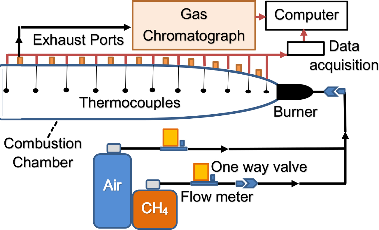
NOTE: A simplified schematic of the setup is shown in Figure 1.

Figure 1. Combustion characterization experimental setup schematic. Combustion characterization experimental setup schematic showing fuel, air and exhaust flows (black arrows) and data flows (red arrows). One-way valves are used to prevent flash back. Please click here to view a larger version of this figure.
3. Combustion Characterization Experiment
- Before testing, push the syringe plunger in fully and open the three-way valve on the exhaust port side.
- Turn the air MFC on first to a flow rate of 86.5 L/min.
- Turn methane MFC on to a flow rate of 10 L/min. This creates a premixed equivalence ratio of 1.10, a slightly rich mixture, which is easier to ignite.
- Turn thermocouples on via the computer module to begin recording data.
- Ignite the mixture at the end of the combustion chamber using a butane lighter. After ignition, the flame should stabilize at the burner front.
- Adjust the equivalence ratio by adjusting the flow rate of air slowly from the initial value of 86.5 L/min to the desired value. Take care to not move too quickly or go outside of the flammability limits which would cause flame quenching.
- Record the temperature reading in a data file after the thermocouples temperatures stabilize.
- Once again, pull the syringe plunger to extract combustion exhaust from the exhaust port.
- After extracting the combustion exhaust, open the three-way valve to the GC side and close the exhaust port side.
- Push the syringe plunger till it closes completely and all of the exhaust has been sent to the GC.
- Repeat steps 3.8-3.10 until all of the residual gases in the copper tubing connecting the port to the GC is removed. A simple analysis of the internal volume of the copper tubing compared to the volume of the syringe will indicate how many times steps 3.8-3.10 need to be repeated.
- After removing all residual gases in the tubing extract a final exhaust sample for analysis. Push the exhaust gas into the GC and turn the GC to analysis mode7,17.
- Record the GC data by saving the GC analysis data.
- Repeat steps 3.1-3.13 until all desired equivalence ratios are tested.
4. Development of the Model Combustion Exhaust
- Plot the combustion exhaust species volume percentage to observe the trends.
- Determine the cut off concentration value for the model combustion exhaust. In developing a model combustion exhaust fuel for initial mT-FFC analysis, only the components appearing in significant proportions (>1%) are included in the model fuel.
- For the model fuel select only those equivalence ratios that generate significant hydrogen and carbon monoxide (>1% for each component) in the exhaust.
- Record the volume percentage for each of the exhaust gas components meeting the criteria of 4.3.
5. Fuel Cell Testing Setup
- Determine the flow rate ranges for each gas. Multiply the volume percentage obtained from the GC analysis results by the total flow rate of the model combustion exhaust desired within each fuel cell.
- Assess the range of flow rates for each combustion exhaust species to determine the maximum and minimum flow for each species.
- Select flow meters according to the same principles described in step 2.1.
- Build the testing apparatus by attaching the flow meters to the gas tanks via copper tubing.
- Set the gas pressure regulators to the prescribed value for the flow meters.
- Place one-way valves in the copper tubing path downstream of each flow meter using a combustible gas.
- Connect all flow meter exit ports together via copper tubing and a manifold.
- Set the micro-tubular SOFC on the inside of steel tubing having an internal diameter just larger than the fuel cell's external diameter. Seal the fuel cell to the steel tubing using ceramic adhesive.
- Connect the steel tubing with micro-tubular SOFC to a piece of ceramic refractory material to hold the fuel cell in the furnace.
- Utilize the 4 probe technique10,11 with current collection and voltage sense wires connected to the micro-tubular SOFC with 2 wires on the anode and 2 wires on the cathode. Ensure that the wires do not cross each other creating shorts.
- Connect the four wires to the four probes of the potentiostat10,11.
- Connect the potentiostat to the computer10,11.
- Place a thermocouple in the furnace with the tip touching the exterior of the micro-tubular SOFC electrolyte10,11.
- Attach thermocouple wires to the data acquisition module.
- Connect the data acquisition module to the computer via the USB port.
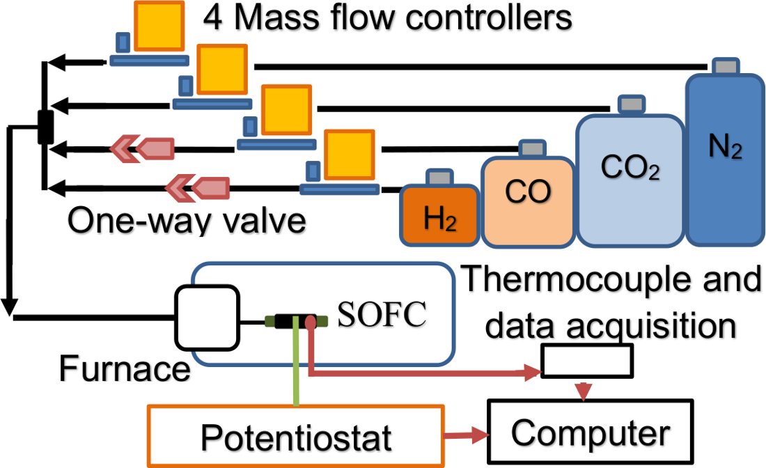
NOTE: Figure 2 is a simplified schematic showing the mT-FFC testing setup. With the model fuel developed and the setup established for controlling the model fuel flow to the fuel cell, testing can proceed according to conventional fuel cell testing methods. These methods are well established in the literature and will not be repeated here.

Figure 2. Micro-tubular flame-assisted fuel cell testing setup schematic. Flows of H2, CO, CO2, N2 (black arrows) are regulated with a MFC and a one-way valve to prevent flash back. Electrons flow (green line) from the SOFC in the furnace to the potentiostat and back to the SOFC. Flow of thermocouple data and electrochemical data is represented by red arrows. Please click here to view a larger version of this figure.
Wyniki
The combustion characterization chamber should be checked prior to testing at the desired equivalence ratios for back-flow of air into the chamber or other air leakage during testing. Combustion processes in open chambers are known to be nearly isobaric. As a result, pressure within the combustion chamber may not be enough to ensure that no air from the external environment is back-flowing into the combustion chamber from the chamber exhaust port or other leakage points. There are several...
Dyskusje
The protocol discussed here is an important bridge between previous combustion characterization research and fuel cell testing. The use of combustion for fuel reforming and fuel cell testing has been applied for several years in DFFC setups10-15. However, the characterization of the combustion process in DFFCs is primarily concerned with in-situ characterization of the flame composition16 and uses a MS8. As the DFFC is open to the ambient, the exhaust composition consists mostly ...
Ujawnienia
The authors have nothing to disclose.
Podziękowania
This work is supported by an agreement with Syracuse University awarded by the Syracuse Center of Excellence in Energy and Environmental Systems with funding under prime award number DE-EE0006031 from the US Department of Energy and matching funding under award number 53367 from the New York State Energy Research and Development Authority (NYSERDA), contract 61736 from NYSERDA, and an award from Empire State Development's Division of Science, Technology and Innovation (NYSTAR) through the Syracuse Center of Excellence, under award number #C120183. This work is supported by the National Science Foundation Graduate Research Fellowship Program under Grant No. 1247399.
Materiały
| Name | Company | Catalog Number | Comments |
| Gas chromotograph | SRI Instruments, Inc. | SRI 8610C | |
| K type thermocouples | Omega | KQXL-116G-6 | Custom length |
| K type thermocouple extension wire | Omega | EXTT-K-20-SLE-100 | |
| Mass flow controller | Omega | FMA5427 | 0-40 L/min (N2) Used for methane |
| Mass flow controller | Omega | FMA5443 | 0-200 L/min (N2) Used for air |
| Mass flow controller | Omega | FMA5402A | 0-10 ml/min (N2) Used for CO |
| Mass flow controller | Brooks Instrument | SLA5850 | 200 SCCM (Propane) Used for CO2 |
| Mass flow controller | Brooks Instrument | SLA5850 | 5 L/min (Air) Used for N2 |
| Mass flow controller | Brooks Instrument | SLA5850 | 500 SCCM (N2) Used for H2 |
| Regulator | Harris Products Group | HP721-125-350-F | Methane tank |
| Regulator | Harris Products Group | HP702-050-590-E | Air tank |
| Regulator | Airgas | Y11-SR145B | CO tank |
| Regulator | Harris Products Group | HP702-050-320-E | CO2 tank |
| Regulator | Airgas | Y12-215B | N2 tank |
| Regulator | Harris Products Group | HP702-015-350-D | H2 tank |
| Methane, Compressed, Ultra high purity | Airgas | UN1971 | Extremely Flammable |
| Air, Compressed, Ultra pure | Airgas | UN1002 | Not classified as hazardous to health. |
| CO, Compressed, Ultra high purity | Airgas | UN1016 | Toxic by inhalation, Extremely flammable |
| CO2, Compressed, Research grade | Airgas | UN1013 | Asphyxiant in high concentrations |
| N2, Compressed, Ultra high purity | Airgas | UN1066 | Not classified as hazardous to health. |
| H2, Compressed, Ultra high purity | Airgas | UN1049 | Extremely flammable, burns with invisible flame |
| Source meter | Tektronix, Inc. | Keithley 2420 | Connects to computer via USB |
| Horizontal split tube furnace | MTI Corportation | OTF-1200X | |
| Data acquisition | National Instruments | NI cDAQ-9172 | Connects to computer via USB |
| Thermocouple input | National Instruments | NI 9211 | Connects to cDAQ-9172 |
| Computer control for Mass Flow Controllers | National Instruments | NI 9263 | Connects to cDAQ-9172 Computer control for Mass Flow Controllers |
| Testing software | National Instruments | LabVIEW 8.6 | |
| Ceramabond | Aremco | 552-VFG | 1 Pint |
Odniesienia
- Gorte, R. J. Recent developments towards commercialization of solid oxide fuel cells. AIChE J. 51 (9), 2377-2381 (2005).
- Milcarek, R. J., Wang, K., Falkenstein-Smith, R. L., Ahn, J. Micro-tubular flame-assisted fuel cells for micro-combined heat and power systems. J. Power Sources. 306, 148-151 (2016).
- Horiuchi, M., Suganuma, S., Watanabe, M. Electrochemical power generation directly from combustion flame of gases, liquids, and solids. J. Electrochem. Soc. 151 (9), A1402-A1405 (2004).
- Starik, A. M., Kuleshov, P. S., Loukhovitski, B. I., Titova, N. S. Theoretical study of partial oxidation of methane by non-equilibrium oxygen plasma to produce hydrogen rich syngas. Int. J. Hydrogen Energy. 40 (32), 9872-9884 (2015).
- Katta, V. R., et al. On flames established with jet in cross flow of fuel-rich combustion. Fuel. 150, 360-369 (2015).
- Maruta, K., et al. Extinction limits of catalytic combustion in microchannels. P. Combustion Institute. 29 (1), 957-963 (2002).
- Ahn, J., Eastwood, C., Sitzki, L., Ronney, P. D. Gas-phase and catalytic combustion in heat-recirculating burners. P. Combustion Institute. 30 (2), 2463-2472 (2005).
- Kӧhler, M., Oßwald, P., Xu, H., Kathrotia, T., Hasse, C. Speciation data for fuel-rich methane oxy-combustion and reforming under prototypical partial oxidation conditions. Chemical Engineering Science. 139, 249-260 (2016).
- Ahn, J., Ronney, P. D., Shao, Z., Haile, S. M. A thermally self-sustaining miniature solid oxide fuel cell. J. Fuel Cell Science and Technology. 6 (4), 041004 (2009).
- Wang, K., Milcarek, R. J., Zeng, P., Ahn, J. Flame-assisted fuel cells running methane. Int. J. Hydrogen Energy. 40 (13), 4659-4665 (2015).
- Wang, K., Zeng, P., Ahn, J. High performance direct flame fuel cell using a propane flame. P. Combust. Inst. 32 (2), 3431-3437 (2011).
- Wang, Y. Q., Shi, Y. X., Yu, X. K., Cai, N. S., Li, S. Q. Integration of solid oxide fuel cells with multi-element diffusion flame burners. J. Electochem. Soc. 160 (11), F1241-F1244 (2013).
- Horiuchi, M., et al. Performance of a solid oxide fuel cell couple operated via in situ catalytic partial oxidation of n-butane. J. Power Sources. 189 (2), 950-957 (2009).
- Wang, Y., et al. The study of portable direct-flame solid oxide fuel cell (DF-SOFC) stack with butane fuel. J. Fuel Chem. Technol. 42 (9), 1135-1139 (2014).
- Wang, K., et al. A high-performance no-chamber fuel cell operated on ethanol flame. J. Power Sources. 177 (1), 33-39 (2008).
- Sun, L., Hao, Y., Zhang, C., Ran, R., Shao, Z. Coking-free direct-methanol-flame fuel cell with traditional nickel-cermet anode. Int. J. Hydrogen Energy. 35 (15), 7971-7981 (2010).
- Zeng, P., Wang, K., Falkenstein-Smith, R. L., Ahn, J. Effects of sintering temperature on the performance of SrSc0.1Co0.9O3-δ oxygen semipermeable membrane. Braz. J. Chem. Eng. 32 (3), 757-765 (2015).
- Turns, S. R. . An Introduction to Combustion: Concepts and Applications. , (2000).
- Glassman, I., Yetter, R. A., Glumac, N. G. . Combustion. , (2015).
Przedruki i uprawnienia
Zapytaj o uprawnienia na użycie tekstu lub obrazów z tego artykułu JoVE
Zapytaj o uprawnieniaThis article has been published
Video Coming Soon
Copyright © 2025 MyJoVE Corporation. Wszelkie prawa zastrzeżone