
Aby wyświetlić tę treść, wymagana jest subskrypcja JoVE. Zaloguj się lub rozpocznij bezpłatny okres próbny.
Method Article
Design of an Open-Source, Low-Cost Bioink and Food Melt Extrusion 3D Printer
* Wspomniani autorzy wnieśli do projektu równy wkład.
W tym Artykule
Podsumowanie
The aim of this work is to design and construct a reservoir-based melt extrusion three-dimensional printer made from open-source and low-cost components for applications in the biomedical and food printing industries.
Streszczenie
Three-dimensional (3D) printing is an increasingly popular manufacturing technique that allows highly complex objects to be fabricated with no retooling costs. This increasing popularity is partly driven by falling barriers to entry such as system set-up costs and ease of operation. The following protocol presents the design and construction of an Additive Manufacturing Melt Extrusion (ADDME) 3D printer for the fabrication of custom parts and components. ADDME has been designed with a combination of 3D-printed, laser-cut, and online-sourced components. The protocol is arranged into easy-to-follow sections, with detailed diagrams and parts lists under the headings of framing, y-axis and bed, x-axis, extrusion, electronics, and software. The performance of ADDME is evaluated through extrusion testing and 3D printing of complex objects using viscous cream, chocolate, and Pluronic F-127 (a model for bioinks). The results indicate that ADDME is a capable platform for the fabrication of materials and constructs for use in a wide range of industries. The combination of detailed diagrams and video content facilitates access to low-cost, easy-to-operate equipment for individuals interested in 3D printing of complex objects from a wide range of materials.
Wprowadzenie
Additive manufacturing is a powerful manufacturing technology that has the potential to provide significant value to the industrial landscape1,2. The attractive features of additive manufacturing involve no tooling costs, high levels of customization, complex geometries, and reduced barriers to entry costs. No retooling costs allow for the rapid manufacturing of prototypes, which is desirable when trying to decrease "time to market", which is a critical aim of industries in developed nations trying to remain competitive against low-wage competitors1. High levels of customizability allow for a wide variety of products to be fabricated with complex geometries. When these factors are combined with the low costs for set-up, materials, and operator specialization, there is a clear value of additive manufacturing technologies3.
Additive manufacturing, also called 3D printing, involves layer-by-layer fabrication of an object in a computer numerical controlled (CNC) system3. Unlike traditional CNC processes such as milling, in which material is removed from a sheet or block of material, a 3D printing system adds material into the desired structure layer-by-layer.
3D printing can be facilitated through a range of methods including laser, flash, extrusion, or jetting technologies4. The specific technology employed determines the form of the raw material (i.e., powder or melt), as well as the rheological and thermal properties required for processing5. The extrusion-based 3D printing market is dominated by filament-based systems, which is due to filaments being easy to handle, process, and continuously supply large volumes of material to the extrusion head. However, this process is limited by the type of material able to be formed into filaments (mainly thermoplastics). Most materials do not exist in filament form, and the lack of modern low-cost platforms in the market represents a notable gap.
This protocol shows the construction of a reservoir-based extrusion system that allows materials to be stored in a syringe and extruded through a needle. This system is ideally suited to manufacture a wide range of materials including foods6, polymers7, and biomaterials8,9. Furthermore, reservoir-based extrusion techniques are typically less hazardous, lower in cost, and easier to operate than other 3D printing methods.
There is a growing number of university-led teams designing and releasing open-source 3D printing systems to the public. Beginning with the Fab@Home extrusion-based printer in 200710,11, researchers aimed to create a simple and cheap platform to drive rapid expansion in 3D printing technology and applications. Later in 2011, the RepRap project aimed to create a filament-based 3D printing platform designed with parts made by 3D printing, with the goal to create a self-replicating machine12. The cost of 3D printers has been dropping over the years, from $2300 USD for a Fab@Home (2006), $573 USD for a RepRap v1 (2005), and $400 USD for v2 (2011).
In previous work, we demonstrated how an off-the-self 3D printing system could be combined with a custom reservoir-based extrusion system to create complex 3D objects from chocolate13. Further design investigation has shown that considerable cost savings can be achieved compared to this prototype design.
The aim of this protocol is to provide instructions for the construction of a low-cost reservoir-based melt extrusion 3D printer. Presented here are detailed diagrams, drawings, files, and component lists to allow successfully construction and operation of a 3D printer. All components are hosted on the open-source (creative commons noncommercial) platform https://www.thingiverse.com/Addme/collections, which allows users to change or add additional features as desired. Viscous cream, chocolate, and Pluronic F-127 (a model for bioinks) are used to evaluate the performance of ADDME and demonstrate application of the ADDME 3D printer to the biomedical and food printing industries.
A laser cutter capable of cutting acrylic and a desktop 3D printer capable of printing PLA or ABS filaments are required for this protocol. A machined heating jacket and heater cartridge or silicone heater can be used to heat the material, depending on which equipment the operator has access to. All CAD files can be found at https://www.thingiverse.com/Addme/designs. For firmware and software to control the 3D printer, http://marlinfw.org/meta/download/ and https://www.repetier.com/ are provided resources, respectively. For detailed instructions about the control board, see https://reprap.org/wiki/RAMPS_1.4.
Access restricted. Please log in or start a trial to view this content.
Protokół
CAUTION: There is a risk of burns caused by hot soldering irons and heating cartridges. The heating cartridge should never be powered when not secured inside of the heating jacket. There is also a risk of pinching or lacerations from the moving 3D printer axis.
1. Overview and preparation
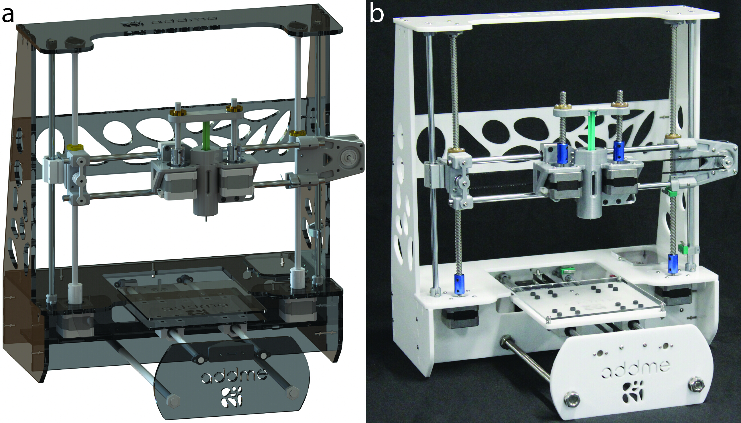
NOTE: Figure 1A shows a computer-generated rendering of the printer and Figure 1B is a photo of the finished printer.
- Procure all parts from the Table of Materials.
- See https://www.thingiverse.com/Addme/designs for all acrylic parts to be laser cut. Insure that 6 mm acrylic is used or the frame will not fit together. Laser cutters use a high energy laser to cut material; a professional shop is preferred here.
- See https://www.thingiverse.com/Addme/designs for all 3D-printed parts. It is important that the printing parameters specified with each part are used. Note that 3D printers have hot surfaces and moving parts, so use the help of a professional.
- Manufacture the heating jacket part, which is found at https://www.thingiverse.com/Addme/designs. If there is no available access to manufacturing capabilities, a silicone heater (Table of Materials) can be purchased with the associated 3D printed holder found at https://www.thingiverse.com/Addme/designs.

Figure 1: Additive manufacturing melt extrusion (ADDME) 3D printer. (A) Computer-generated rendering of the printer. (B) Photograph of a finished printer. Please click here to view a larger version of this figure.
2. Frame assembly
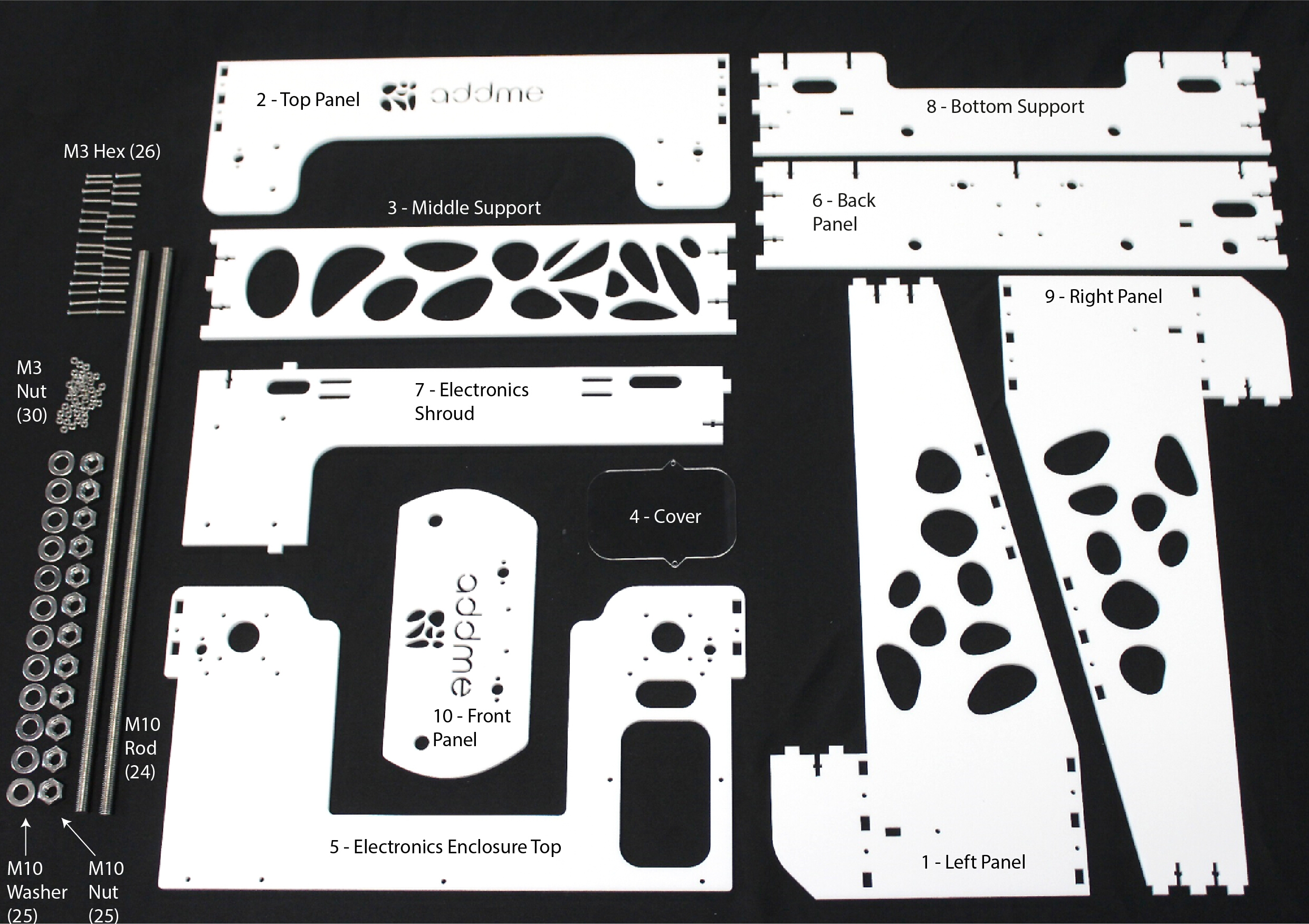
NOTE: The parts shown in Figure 2 are required to finish the frame assembly. The frame of the melt extrusion 3D printer is held together by a combination of 6 mm laser cut acrylic and M3 bolts and nuts (Figure 3). The bottom of the printer is further strengthened with a M10 threaded rod and nut combination.
- Gather acrylic parts 1–9 and place them together into the configuration shown in Figure 3A. Check the figure labels to ensure that each piece is located correctly. Secure with M3 screws and nuts in the configuration shown in Figure 3C using the M3 Allen key.
- Place the M10 threaded rod through the purpose made holes in acrylic members 6, 8, and 10. Secure them with M10 washers and nuts as shown in Figure 3B,D. Tighten with the variable spanner.

Figure 2: Components needed to assemble the frame. Please click here to view a larger version of this figure.

Figure 3: Frame assembly. (A) Assembled frame. (B) An exploded view with labeled acrylic parts and supporting M10 threaded rods. (C) An exploded view showing how each acrylic part is connected to one another, using M3 screws and nuts to hold the frame together. (D) An exploded view showing how the threaded rod holds acrylic parts 6, 8, and 9 together with M10 nuts and washers. Please click here to view a larger version of this figure.
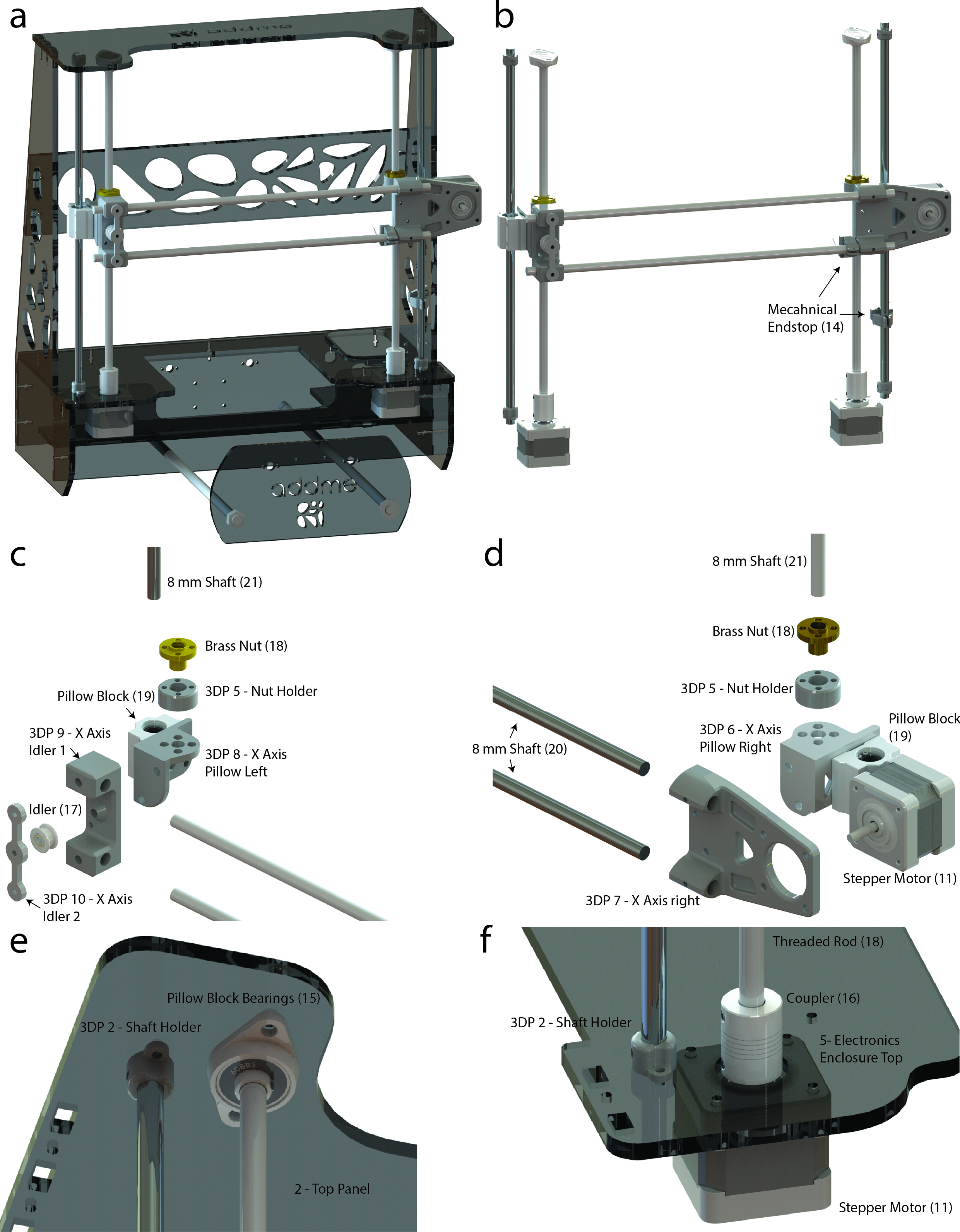
3. Y-axis and printing bed sub-assembly
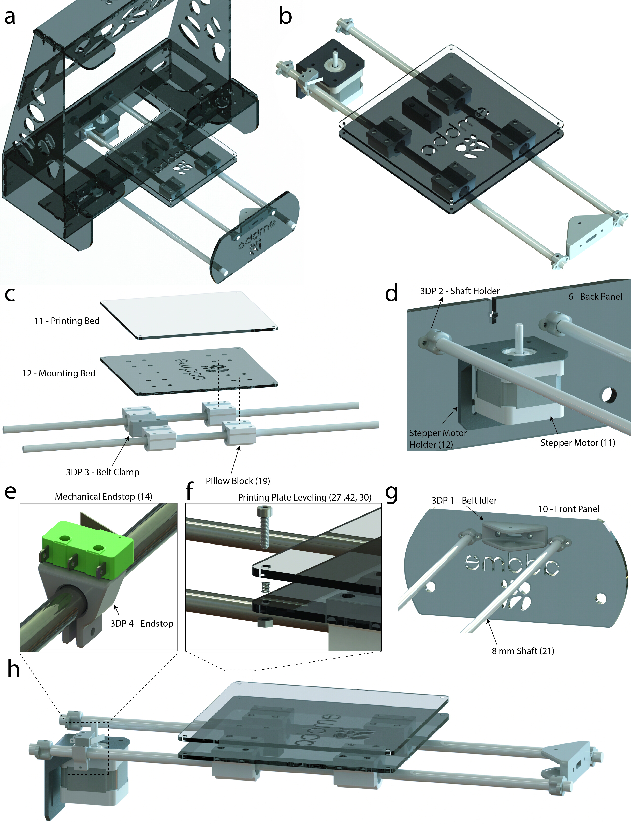
NOTE: The parts outlined in Figure 4 are required to finish the y-axis and printing bed sub-assembly. All screws are seen in Figure 4, and tools are listed in the Table of Materials.
- Using the parts in Figure 4, assemble the printing bed sub-assembly head according to Figure 5C.
- Slide two pillow blocks (19) onto each 8 mm shaft (21) according to Figure 5C. Slide the endstop (3DP 4) onto one of the 8 mm shafts (21) and secure the mechanical endstop (14) using M2 screws and an Allen key according to Figure 5E.
- Secure all four pillow blocks (19) to the mounting bed (acrylic part 12) using the M4 screws and Allen key (Figure 5C). Secure the belt clamp (3DP 3) onto the mounting bed (acrylic part 12) using the M3 screws and Allen key (Figure 5C). Secure the printing bed (acrylic part 11) onto the mounting bed (12) (Figure 5C) using the M3 screw, nut, and spring arrangement according to Figure 5F.
- Secure the remaining parts from Figure 4 to the frame according to Figure 5D,G.
- Secure two of the shaft holders (3DP 2) to both the back panel (acrylic part 6) and front panel (acrylic part 10) using the M2 screws and Allen key according to Figure 5D,G, respectively.
- Secure the stepper motor holder (12) to the back panel (acrylic part 6) using the M3 screws and Allen key (Figure 5D). Secure the stepper motor (11) to the stepper motor holder (12) using the M3 screws and Allen key (Figure 5D). Secure the belt idler (3DP 1) to the front panel (acrylic part 10) using the M3 screws and Allen key (Figure 5G).
- Place the printing bed sub-assembly into the frame by matching up each end of an 8 mm shaft (21) to a shaft holder (3DP 2) according to Figure 5A,D,G.
NOTE: It may be necessary to loosen the M12 washers on the front panel (acrylic part 10) to create space to place the printing bed sub-assembly into the frame. - Finally, to complete the y-axis and printing bed sub-assembly, screw the idler to the belt idler (3DP 1) by using an M3 screw, then secure the idler toothed to the stepper motor by tightening the M2 grub screw on the idler toothed with the M2 Allen key. Slide the belt (17) around the idler (17) and idler toothed (17) and into the belt clamp (3DP 3) to produce tension in the belt. Complete the section by tightening the belt clamp (3DP 3) with the M3 Allen key.

Figure 4: Components needed to put together the y-axis and printing bed sub-assembly. Please click here to view a larger version of this figure.

Figure 5: Additive manufacturing melt extrusion (ADDME) 3D printer. (A) Graphical rendering of the frame, y-axis, and bed. (B) Graphical rendering of the y-axis and bed. (C) Exploded view of the bed sub-assembly. (D) Labeled view showing how the y-axis connects to the back panel. (E) Zoomed-in view of the mechanical endstop. (F) Exploded view of the printing plate spring leveling system. (G) Labeled view showing how the y-axis connects to the front panel. (H) Side view graphical render of the y-axis and bed. Please click here to view a larger version of this figure.
4. X-axis sub-assembly
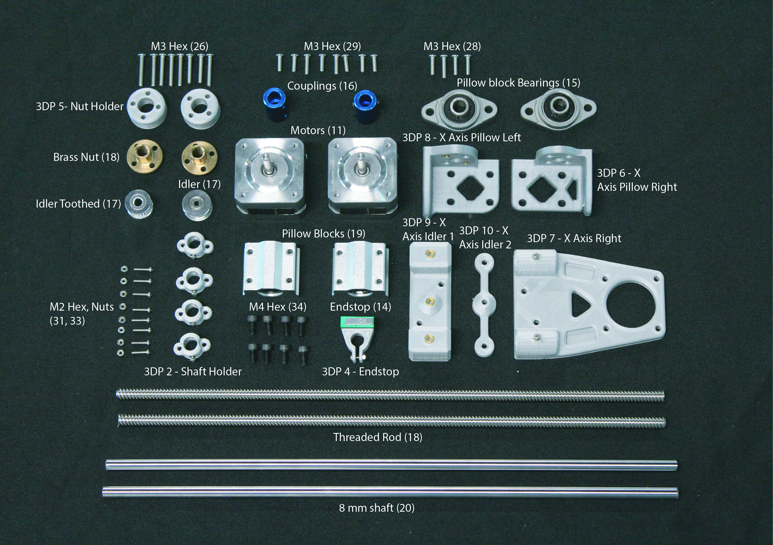
NOTE: The parts outlined in Figure 6 are required to finish the x-axis sub-assembly. All screws are seen in Figure 6, and tools are listed in the Table of Materials.
- Using the parts in Figure 6, assemble the left side of the x-axis sub-assembly according to Figure 7C.
- Place the brass nut (18) inside of the nut holder (3DP 5) and secure to the x-axis pillow left (3DP 8) using the M3 screws and Allen key (Figure 7C).
- Secure the pillow block (19) onto the x-axis pillow left (3DP 8) using the M4 screws and Allen key (Figure 7C). Secure the x-axis idler 1 (3DP 9) to the x-axis pillow left (3DP 8) using the M3 screws and Allen key (Figure 7C).
- Align the center holes of the idler (17), x-axis idler 1 (3DP 9), and x-axis Idler 2 (3DP 10). Secure using the M3 screws and Allen key (Figure 7C). Using the parts shown in Figure 6, assemble the right side of the x-axis sub-assembly according to Figure 7D.
- Place the brass nut (18) inside of the nut holder (3DP 5) and secure to the x-axis pillow right (3DP 6) using the M3 screws and Allen key (Figure 7D).
- Secure the pillow block (19) onto the x-axis pillow right (3DP 6) using the M4 screws and Allen key (Figure 7D). Secure the x-axis right (3DP 7) to the x-axis pillow right (3DP 6) using the M3 screws and Allen key (Figure 7D). Secure the stepper motor (11) to the x-axis right (3DP 7) using the M3 screws and Allen key (Figure 7D).
- Thread each of the threaded rods (18) into each of the brass nuts (18) according to Figure 7B. Slide two of the 8 mm shafts (20) into each of the pillow blocks (19) vertically, and two of the 8 mm shafts (20) horizontally according to Figure 7B,C,D.
- Secure the remaining parts from Figure 6 to the frame according to Figure 7E,F.
- Secure two of the shaft holders (3DP 2) to both the top panel (acrylic part 2) and electronics enclosure top (acrylic part 5) using the M2 screws and Allen key (Figure 7E,F). Secure the pillow block bearings (15) onto the top panel (acrylic part 2) using the M3 screws and Allen key (Figure 7E). Secure the stepper motors (11) onto the electronics enclosure top (acrylic part 5) using the M3 screws and Allen key (Figure 7F).
NOTE: The coupler (16) is a component that is designed to connect two different shaft sizes. - Secure the coupler (16) over the shafts of the stepper motors (11) by tightening the lower grub screw with the M2 Allen key (Figure 7F).
- Secure two of the shaft holders (3DP 2) to both the top panel (acrylic part 2) and electronics enclosure top (acrylic part 5) using the M2 screws and Allen key (Figure 7E,F). Secure the pillow block bearings (15) onto the top panel (acrylic part 2) using the M3 screws and Allen key (Figure 7E). Secure the stepper motors (11) onto the electronics enclosure top (acrylic part 5) using the M3 screws and Allen key (Figure 7F).
- Place the x-axis sub-assembly into the frame by aligning the vertical 8 mm shafts with the shaft holder (3DP 2) and tighten using the M2 screws and Allen key (Figure 7E,F). Secure the threaded rod (18) into the other end of the coupler (16) by tightening the upper grub screw with the M2 Allen key (Figure 7E,F).
NOTE: The top panel (acrylic part 2) may need to be temporarily removed so that the x-axis sub assembly can fit into the frame.

Figure 6: Components needed to put together the x-axis sub-assembly. Please click here to view a larger version of this figure.

Figure 7: X-axis sub assembly. (a) Graphical rendering of the frame and x-axis. (b) Graphical render of the x-axis. (c) Exploded view of the left side of the sub assembly. (d) Exploded view of the right side of the sub-assembly. (e) Labeled view showing how the x-axis connects to the top panel. (f) Labeled view showing how the x-axis connects to the electronics enclosure. Please click here to view a larger version of this figure.
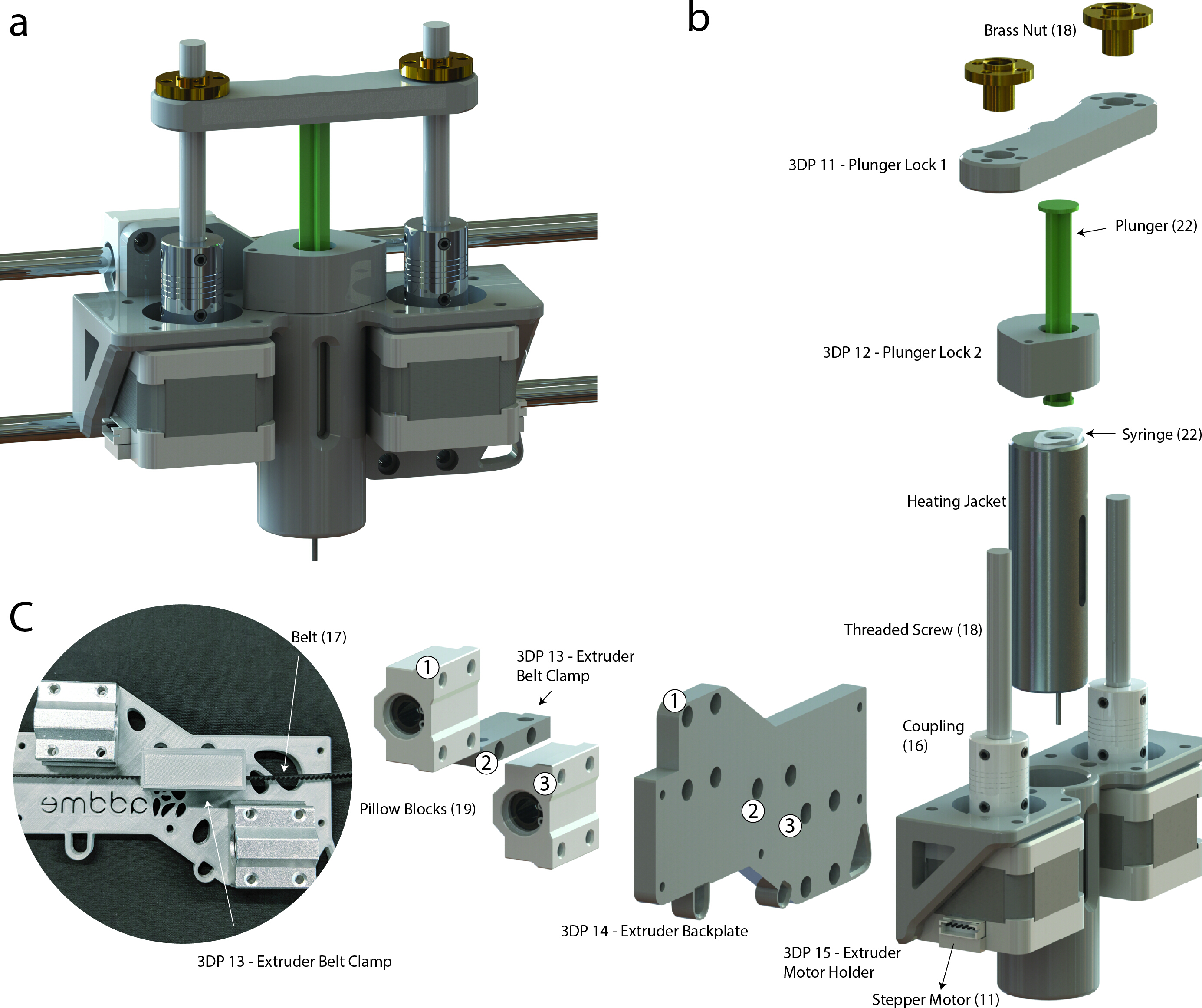
5. Extrusion sub-assembly
NOTE: The extrusion sub-assembly utilizes a dual stepper motor design to ensure that a high level of accuracy is achieved through the balancing of forces on each side of the plunger. The parts outlined in Figure 8 are required to finish the extrusion sub-assembly.
- Gather all parts shown in Figure 8 and assemble the extrusion head according to Figure 9.
NOTE: Figure 9B is an exploded view of the extruder sub-assembly that shows how each component fits together. The following steps explain how this is done. All screws are seen in Figure 8, and tools are listed in the Table of Materials.- Secure the two pillow blocks (19) onto the extruder backplate (3DP 14) using the M4 screws and Allen key (Figure 9B). Secure the extruder belt clamp (3DP 13) onto the extruder backplate (3DP 14) between the pillows blocks (19) using the M3 screws and Allen key (Figure 9B).
- Secure the extruder backplate (3DP 14) to the extruder motor holder (3DP 15) using the M3 hex screws and Allen key (Figure 9B). Secure the two stepper motors (11) onto the extruder motor holder (3DP 15) using the M3 hex screws and Allen key (Figure 9B).
NOTE: The coupler (16) is a component that is designed to connect two different shaft sizes. - Secure the couplers (16) over the shafts of the stepper motors (11) by tightening the lower grub screw with an M2 Allen key (Figure 9B). Secure the threaded screw (18) within the couplers (16) by tightening the upper grub screw (Figure 9B).
- Slide the heating jacket or silicone heater into the extruder motor holder (3DP 15) according to Figure 9B. Secure the brass nuts (18) inside plunger lock 1 (3DP 11) using the M3 screws and Allen key.
- Mount the extrusion head onto the x-axis according to Figure 9A.
- Slide the 8 mm shafts found on the x-axis into the pillow blocks (19) on the extruder head according to Figure 9A.
- Wrap the drive belt (17) through the idler (17) and idler toothed (17) located on the left and right x-axis assemblies and secure the drive belt (17) in the extruder belt clamp (3DP 13) using the M3 hex screws and Allen key (Figure 9C).

Figure 8: Components needed to assemble the extruder. Please click here to view a larger version of this figure.

Figure 9: Extruder sub-assembly. (A) Graphical rendering of the extruder sub-assembly. (B) Exploded view showing extruder components. Please click here to view a larger version of this figure.
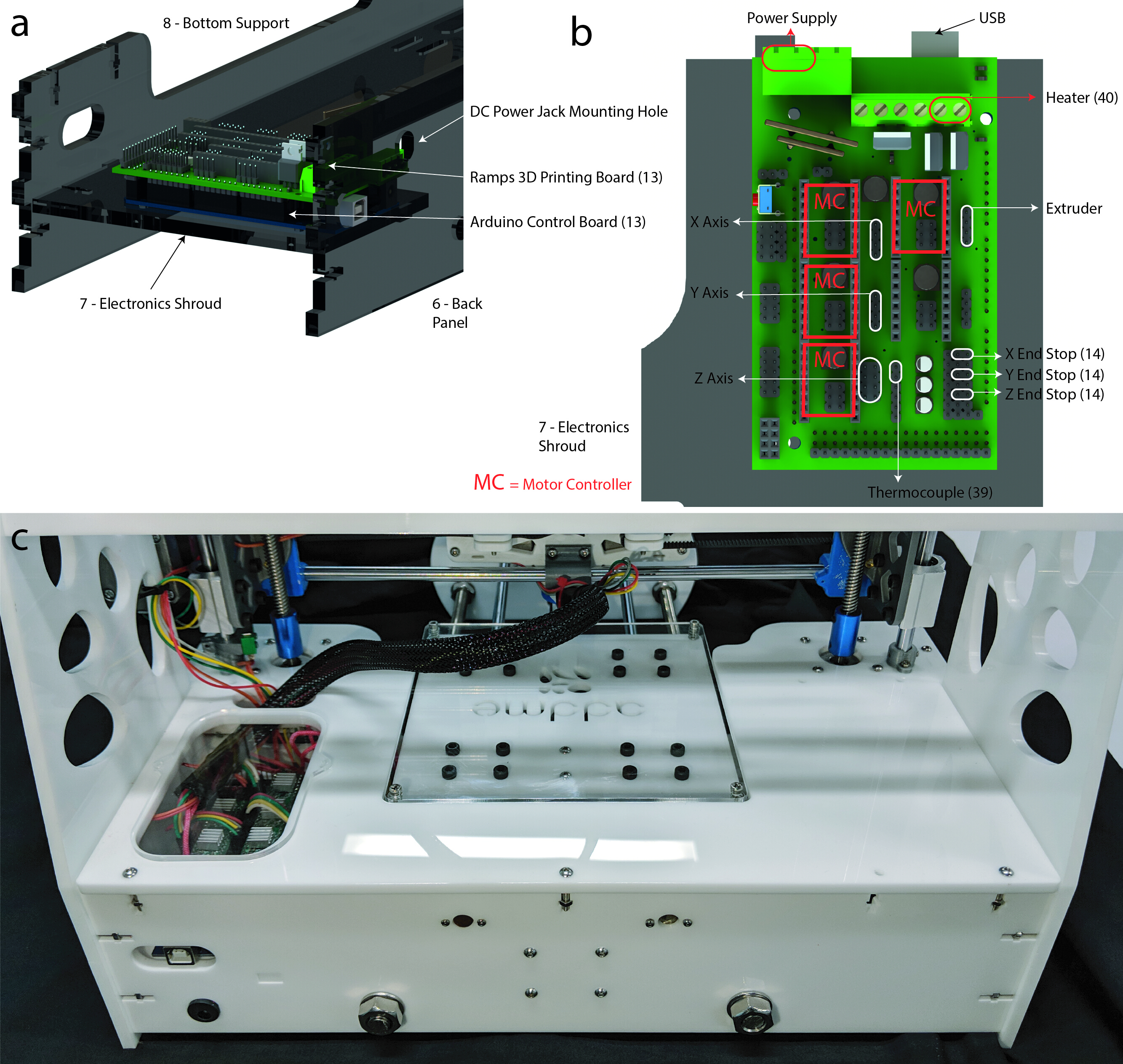
6. Electronics and wiring
- Mount the Arduino into acrylic part 7 (electronics shroud, shown in Figure 10A) with M3 hex screws using a M3 Allen key. Insert a ramps board on top of the Arduino board oriented as shown in Figure 10A,B with the USB plug facing acrylic part 6 (back panel).
- Mount the DC power supply jack in acrylic part 6 (back panel, as shown in Figure 10A) and connector to the power supply in Figure 10B. Connect the motor controllers, stepper motors, end stops, heater, and thermocouple to the respective pins (Figure 10B).

Figure 10: Electronics. (A) Graphical rendering of the electronics control board mounting location. (B) Connection diagram of electrical components and motors to 3D printing board [Jos Hummelink (grabcab.com) provided the Arduino and Ramps CAD files]. (c) Image of the finished wiring. Wires can be seen leading from the Ramps board, then to the extrusion head and x/y axis motors. Please click here to view a larger version of this figure.
7. Software, control, and calibration
NOTE: For more detailed instructions and troubleshooting information, see https://reprap.org/wiki/RAMPS_1.4.
- Download firmware from http://marlinfw.org/meta/download/.
- Install repetier https://www.repetier.com/.
- Replace the file .configuration in the firmware found in https://www.thingiverse.com/Addme/designs.
- Set buad rate in repetier to 112500 by navigating (in repetier) to Configure | Printer Settings | Connection | Baud Rate: 115200.
- Click the Connect icon in repetier.
- Once connected, full control over the printer is achieved. Navigate to Manual Control to move the printing bed and try setting the temperature.
CAUTION: Make sure that the maximum temperature of the syringe or housing components is not exceeded (see the discussion for more information). While the stepper motors have limited power, the movement of the axis presents a mechanical hazard.
NOTE: At this stage there is a fully operating printer. In the following section (section 8), the procedure for getting the printer ready for 3D printing is described.
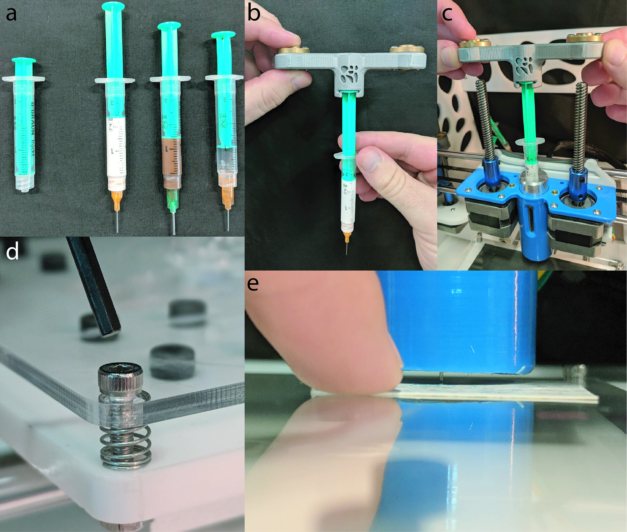
8. Preparation for 3D printing
- Load a 2 mL syringe with the desired material, such as viscous cream, chocolate, or pluronic (Figure 11A).
- To place the syringe into the extrusion head, start by inserting the syringe into plunger lock 1 (3DP 11, Figure 11B). Next, insert the syringe into the heating jacket while carefully turning the threaded screws (Figure 11C).
- Optional: if the bed has not been leveled, it is necessary to level it. Move the printing head left and right then up and down, and check if the distance between the bed and syringe nozzle is consistent. Slide a piece of paper between the syringe and bed and feel the friction (Figure 11E), then use the M3 Allen key (Figure 11D) to adjust the bed level if required.
- Optional: if the chosen material needs to be heated, do this now. Navigate to the Manual Control tab in repetier and set the temperature to the desired level.

Figure 11: 3D printing preparation. (A) A 2 mL syringe loaded with (from left to right) viscous cream (150 mL, Nivea hand cream), chocolate (Cadbury, plain milk), and Pluronic F-127 (Sigma Aldrich). (B) Plunger being inserted into the plunger lock 1 (3DP 11). (C) Shown is a syringe being inserted into the heating jacket, while the threaded screws are catching on the brass nuts. (D) Shown is an Allen key about to be inserted into the retaining M3 hex screw, allowing the level to be adjusted. (E) A business card is then slid under the syringe to check the distance between the bed and syringe. Please click here to view a larger version of this figure.
Access restricted. Please log in or start a trial to view this content.
Wyniki
The performance of ADDME during 3D printing was evaluated using a viscous cream (150 mL, Nivea hand cream), chocolate (Cadbury, plain milk), and Pluronic F-127 (Sigma Aldrich). The viscous cream and chocolate were used as is, and the Pluronic was dissolved into a 20% wt solution with ultrapure water and stored refrigerated at 5 °C until needed14,15.
Line testing inv...
Access restricted. Please log in or start a trial to view this content.
Dyskusje
This protocol provides detailed instructions for constructing a low-cost melt extrusion-based 3D printer. Construction of the 3D printer can be broken down into subsections including frame, y-axis/bed, x-axis, extruder, electronics, and software. These subsections are presented with detailed diagrams, drawings, files and parts lists. The total price of an ADDME 3D printer comes to $343 AUD ($245 USD as of 01/17/2019), making this the cheapest, reservoir-based melt extrusion 3D printer currently known. It was aimed to mak...
Access restricted. Please log in or start a trial to view this content.
Ujawnienia
The authors have nothing to disclose.
Podziękowania
This research did not receive any specific grants from funding agencies in the public, commercial, or not-for-profit sectors. Special thanks to Florian Schmittner, Sandro Gorka, Gurinder Singh, Vincent Tran, and Dominik Vu for their contribution on an earlier prototype of the design.
Access restricted. Please log in or start a trial to view this content.
Materiały
| Name | Company | Catalog Number | Comments |
| 15 W 12V DC 50x100mm Flexible Silicon Heater | Banggood | 1280175 | Optional; AU$4.46 |
| 3D Printer | Lulzbot | https://download.lulzbot.com/ | |
| 3D Printer | Ultimaker | Ultimaker 2+ | |
| AC 100-240V to DC 12V 5A 60W Power Supply | Banggood | 994870 | AU$12.7 |
| Acrylic Sheet White Continuous Cast 1200x600mm | Mulford Plastics | AU$36.95 | |
| Allen Keys | Metric | ||
| Arduino MEGA2560 R3 with RAMPS 1.4 Controller | Geekcreit | 984594 | AU$28.91 |
| Carbon Steel Linear Shaft 8mm x 350mm | Banggood | 1119330 | AU$13.44 |
| Carbon Steel linear Shaft 8mm x 500mm | Banggood | 1276011 | AU$19.42 |
| Chocolate | Cadbury | ||
| Computer with internet access | Dell | ||
| Coupler 5-8mm | Banggood | 1070710 | AU$6.93 |
| Hand Cream | Nivea | 80102 | |
| Heating Cartridge | Creality 3D | 1192704 | AU$4.75 |
| K Type Temperature Sensor Thermocouple | Banggood | 1212169 | AU$2.37 |
| Laser Cutter | trotec | Speedy 300 | https://www.troteclaser.com/ |
| M10 1mm Pitch Thread Metal Hex Nut + Washer | UXCELL | AU$8.84 | |
| M10 1mm Pitch Zinc Plated Pipe 400mm Length | UXCELL | AU$11.62 | |
| M2 - 0.4mm Internal Thread Brass Inserts | Ebay | AU$5.65 | |
| M2 Nuts | Suleve | 1239291 | AU$9.17 |
| M2 x 10 mm Button Hex Screws | Suleve | 1239291 | AU$9.17 |
| M2 x 5mm Button Hex Screws | Suleve | 1239291 | AU$9.17 |
| M3 - 0.5mm Internal Thread Brass Inserts | Suleve | 1262071 | AU$7.5 |
| M3 Nuts | Suleve | 1109208 | AU$7.85 |
| M3 Washer | Banggood | 1064061 | AU$3.05 |
| M3 x 10mm Button Hex Screws | Suleve | 1109208 | AU$7.85 |
| M3 x 20mm Button Hex Screws | Suleve | 1109208 | AU$7.85 |
| M3 x 6mm Button Hex Screws | Suleve | 1109208 | AU$7.85 |
| M3 x 8mm Button Hex Screws | Suleve | 1109208 | AU$7.85 |
| M4 x 8mm Button Hex Screws | Suleve | 1273210 | AU$4.32 |
| Needle Luer Lock 18 - 27 Gauge | Terumo | TGA ARTG ID: 130227 | AU$3.57 |
| NEMA 17 Stepper Motor | Casun | 42SHD0001-24B | AU$54 |
| NEMA Stepper Motor Mounting Bracket | Banggood | ptNema17br90 | AU$4.79 |
| Pillow Block Flange Bearing 8mm | Banggood | KFL08 | AU$5.04 |
| PLA Filament | Creality 3D | 1290153 | AU$24.95 |
| Pluronic F127 | Sigma Aldrich | P2443-250G | |
| SC8UU 8mm Linear Motion Ball Bearing | Toolcool | 935967 | AU$21.6 |
| SG-5GL Micro Limit Switch | Omron | 1225333 | AU$4.5 |
| Soldering Station | Solder, Wires, Heat shrink e.c.t. | ||
| Spring | Banggood | 995375 | AU$2.53 |
| Syringe 3ml Luer Lock Polypropylene | Brauhn | 9202618N | AU$3.14 |
| Timing Pulley GT2 20 Teeth and Belt Set | Banggood | 10811303 | AU$11.48 |
| Trapezoidal Lead Screw and Nut 8mm x 400mm | Banggood | 1095315 | AU$29.02 |
| Variable Spanner |
Odniesienia
- Brettel, M., Friederichsen, N., Keller, M., Rosenberg, M. How Virtualization, Decentralization and Network Building Change the Manufacturing Landscape: An Industry 4.0 Perspective. World Academy of Science, Engineering and Technology International Journal of Information and Communication Engineering. 8 (1), (2014).
- Gilchrist, A. Introducing Industry 4.0. Industry 4.0. , 195-215 (2016).
- Petrick, I. J., Simpson, T. W. 3D Printing Disrupts Manufacturing: How Economies of One Create New Rules of Competition. Research-Technology Management. 56 (6), 12-16 (2013).
- Wong, K., Hernandez, A. A Review of Additive Manufacturing. ISRN Mechanical Engineering. 10, (2012).
- Lanaro, M., Desselle, M. R., Woodruff, M. A. 3D Printing Chocolate: Properties of Formulations for Extrusion, Sintering, Binding and Ink Jetting. Fundamentals of 3D Food printing and Applications. , (2018).
- Godoi, F. C., Prakash, S., Bhandari, B. R. 3d printing technologies applied for food design: Status and prospects. Journal of Food Engineering. 179, 44-54 (2016).
- Stansbury, J. W., Idacavage, M. J. 3D printing with polymers: Challenges among expanding options and opportunities. Dental Materials. 32 (1), 54-64 (2016).
- Zhu, W., Ma, X., Gou, M., Mei, D., Zhang, K., Chen, S. 3D printing of functional biomaterials for tissue engineering. Current Opinion in Biotechnology. 40, 103-112 (2016).
- Lanaro, M., Booth, L., Powell, S. K., Woodruff, M. A. Electrofluidodynamic technologies for biomaterials and medical devices: melt electrospinning. Electrofluidodynamic Technologies (EFDTs) for Biomaterials and Medical Devices. , 37-69 (2018).
- Malone, E., Lipson, H. Fab@Home: the personal desktop fabricator kit Article information. Rapid Prototyping Journal. 13 (4), 245-255 (2007).
- Vilbrandt, T., Malone, E., Lipson, H., Pasko, A. Universal Desktop Fabrication. Heterogeneous Objects Modelling and Applications. , 259-284 (2008).
- Jones, R., et al. RepRap-the replicating rapid prototyper. Robotica. 29, 177-191 (2011).
- Lanaro, M., et al. 3D printing complex chocolate objects: Platform design, optimization and evaluation. Journal of Food Engineering. , (2017).
- Wu, W., DeConinck, A., Lewis, J. A. Omnidirectional Printing of 3D Microvascular Networks. Advanced Materials. 23 (24), H178-H183 (2011).
- Paxton, N., Smolan, W., Böck, T., Melchels, F., Groll, J., Jungst, T. Proposal to assess printability of bioinks for extrusion-based bioprinting and evaluation of rheological properties governing bioprintability. Biofabrication. 9 (4), 044107(2017).
Access restricted. Please log in or start a trial to view this content.
Przedruki i uprawnienia
Zapytaj o uprawnienia na użycie tekstu lub obrazów z tego artykułu JoVE
Zapytaj o uprawnieniaThis article has been published
Video Coming Soon
Copyright © 2025 MyJoVE Corporation. Wszelkie prawa zastrzeżone