Aby wyświetlić tę treść, wymagana jest subskrypcja JoVE. Zaloguj się lub rozpocznij bezpłatny okres próbny.
Method Article
Fibroblast Derived Human Engineered Connective Tissue for Screening Applications
W tym Artykule
Podsumowanie
Presented here is a protocol to generate engineered connective tissues for a parallel culture of 48 tissues in a multi-well plate with double poles, suitable for mechanistic studies, disease modeling, and screening applications. The protocol is compatible with fibroblasts from different organs and species and is exemplified here with human primary cardiac fibroblasts.
Streszczenie
Fibroblasts are phenotypically highly dynamic cells, which quickly transdifferentiate into myofibroblasts in response to biochemical and biomechanical stimuli. The current understanding of fibrotic processes, including cardiac fibrosis, remains poor, which hampers the development of new anti-fibrotic therapies. Controllable and reliable human model systems are crucial for a better understanding of fibrosis pathology. This is a highly reproducible and scalable protocol to generate engineered connective tissues (ECT) in a 48-well casting plate to facilitate studies of fibroblasts and the pathophysiology of fibrotic tissue in a 3-dimensional (3D) environment. ECT are generated around the poles with tunable stiffness, allowing for studies under a defined biomechanical load. Under the defined loading conditions, phenotypic adaptations controlled by cell-matrix interactions can be studied. Parallel testing is feasible in the 48-well format with the opportunity for the time-course analysis of multiple parameters, such as tissue compaction and contraction against the load. From these parameters, biomechanical properties such as tissue stiffness and elasticity can be studied.
Wprowadzenie
A major obstacle in the study of fibrotic diseases is the lack of representative human 3D tissue models that provide insight into the behavior of fibroblasts and their pathological derivatives. To study fibrotic processes, standard 2D culture systems are sub-optimal since isolated fibroblasts transdifferentiate rapidly into α-smooth muscle actin (SMA)-expressing myofibroblasts when cultured on non-compliant 2D substrates1,2,3. Thus, fibroblasts in the standard 2D culture do not reflect a regular "healthy" tissue phenotype3,4,5,6. Cultures on pliable substrates have been introduced to simulate non-fibrotic (10 kPa) and fibrotic (35 kPa) tissue environments7, but these lack the third dimension, which is very important with respect to pathophysiology. Tissue engineering provides the opportunity to overcome this limitation by allowing fibroblast culture in a defined and experimentally tunable extracellular matrix (ECM)-context, for example, by alterations in the cellularity, ECM composition, and ECM concentration, all of which can determine the tissue biomechanics.
Various 3D models have been generated using fibroblasts. Floating discs and microspheres were among the first and demonstrate that collagen is remodeled and compacted in a time-dependent manner. Fibroblasts exert traction forces on collagen fibrils, a process which can be facilitated by the addition of pro-fibrotic agents such as transforming growth factor-beta 1 (TGF-β1)8,9,10,11,12,13,14,15,16. However, freely floating cultures do not allow for the controlled external loading and, therefore, constitute continuously shrinking or compacting models. Sheet-like engineered tissues opened the possibility of studying homeostatic regulation of biomechanical properties of tissues, namely through uni, bi, multiaxial, or cyclic strain testing17,18,19,20. These models have been used, e.g., to demonstrate the influence of the cell number on the tissue stiffness, which was found to correlate positively with cytoskeleton integrity and actomyosin cytoskeleton contractility18,19. However, it is important to note that force-to-strain conversions are complicated by the non-uniform tissue deformation around clamp points of force transducers and anchor points. This inherent limitation can be bypassed by dog-bone or ring-shaped tissues, offering some tissue enforcement at anchor-points21,22,23. Ring-shaped tissues can be prepared by distributing a cell-collagen hydrogel into ring-shaped molds. As the hydrogel compacts, a tissue forms around the uncompressible inner rod of the mold, which offers resistance for further tissue contraction24,25,26,27. After initial and typically maximal compaction, tissues may also be transferred to adjustable spacers to further restrain circular ECT at a defined tissue length3,24,25,26,27,28,29,30. Biophysical properties can be assessed in standard horizontal or vertical strain-stress devices with appropriate load cells under unidirectional or dynamic strain3. As the tissues have a largely uniform circular structure and can be held on bars/hooks (anchorage points and/or force transducers), although these may still enclose compression areas around the loading bars, this format allows a more uniform strain variation as compared to clamping3. Furthermore, anchored tissues elicit a bipolar cell shape, and cells adapt to the tissue forces by elongation along force lines promoting anisotropic traction31,32,33,34,35,36. We have previously applied ring-shaped ECT from rat and human cardiac fibroblasts (CF) around a single stiff pole in functional stress-strain experiments and performed gain and loss of function studies by using virally transduced fibroblasts24,25,26 and pharmacological studies37. Further, we could identify sex differences in CF-mediated fibrosis in the ECT model27.
The following protocol for the generation of human ECT, exemplified with primary human CF obtained as cryopreserved CF from commercial vendors (see Table of Materials), combines the advantages of ring-shaped tissues with an easy and fast way of producing macroscopic tissues for a 48-well platform designed for parallel high-content testing.
Importantly, the ECT model is not restricted to a specific fibroblast type, with the documented use in the investigation of other fibroblasts, e.g., skin fibroblasts38,39. Moreover, fibroblasts from patient's biopsies work equally well, and the choice of fibroblasts ultimately depends on the scientific question to be addressed.
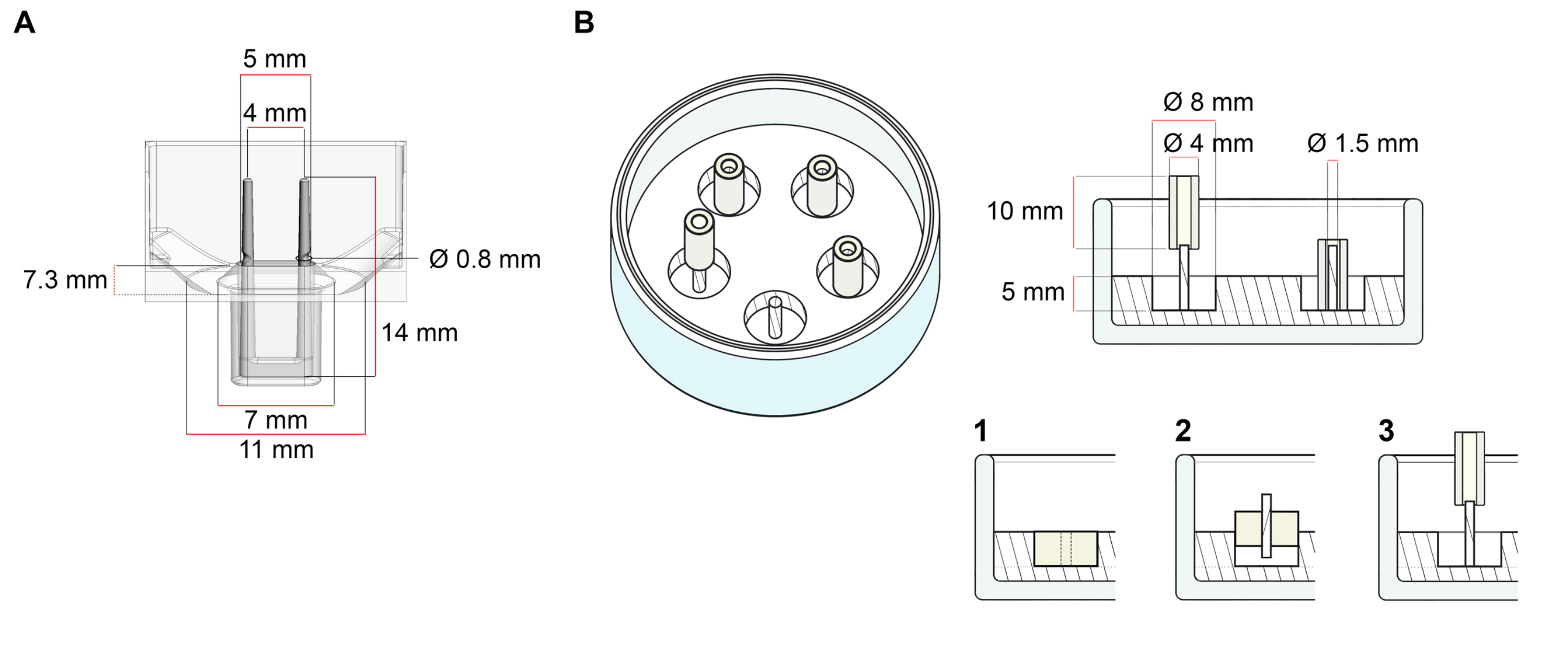
The platform used for the generation of ECT described in this protocol is a commercially available 48-well 3D cell/tissue culture plate (Figure 1A). The methods for the preparation, culturing, and monitoring ECT formation and function under a defined geometry and mechanical load with the help of the 48-well plate are described. The formed ECT are held by integrated flexible poles and the mechanical load can be fine-tuned according to the final purpose by using poles with different hardness (Shore A value 36-89), influencing their bending stiffnesses. Poles with a shore A value of 46 are recommended. The protocol is, in addition, compatible with a previously described custom circular mold, where the ECT is held around a single stiff rod37. The dimensions of this mold are given in Figure 1B.

Figure 1: Schematic representation of casting molds. (A) Technical drawing and dimensions of a casting mold with two flexible poles. The mold comprises an inner circumference delimited by a short wall that holds double retaining poles at the mold's main body. The flexible poles have a free horizontal distance to one another and are connected at the base. The mold allows for 180 µL casting volume. The well of each mold allows a volume capacity of at least 600 µL of culture media. Different material compositions can be used to produce poles with specific stiffnesses (e.g., TM5MED-TM9MED). (B) Technical drawing and dimensions of a ring-shaped mold with a single stiff rod. This is an alternative mold with distinct geometry and mechanical environment, which can be used with the ECT casting protocol37. The ring-shaped mold assembly method was adapted from published bigger formats28,41. In brief, the method includes (1) imprinting polytetrafluoroethylene (PTFE) molding spacers (8 mm diameter) in polydimethylsiloxane (PDMS, silicone) poured into glass dishes (diameter 60 mm), and (2) fixing a PDMS pole holder (1.5 mm diameter) concentrically inside of the formed hollow cavity, which serves to (3) hold a removable pole (4 mm diameter silicone tube). The hollow space resultant allows for 180 µL of casting volume. Each glass dish can comport multiple imprinted molds (exemplarily shown with 5 molds) and has the capacity for up to 5 mL of culture medium. Please click here to view a larger version of this figure.
Protokół
All steps must be undertaken in a Class II biosafety hoods installed in laboratories under containment level 1. Depending on local regulations and type of manipulations to be performed, such as viral-mediated gene transfer, the containment level must be increased to the biosafety level 2 or 3. All cultures are maintained at 37 °C in a cell culture incubator with a humidified atmosphere of 5 % CO2 in the air. Note that the volumes (Steps 1 and 2) are provided for a T75 cell culture flask. Adjust the volumes to different culture formats according to the standard cell culture recommendations.
1. Thawing and pre-plating primary cardiac fibroblast (CF) for monolayer culture (5-12 days)
NOTE: As an alternative, HFF-1 cells can be used following the standard sub-culture protocol as advised by the supplier.
- Prepare the fibroblast growth medium (FGM) according to the manufacturer's instructions. Optionally, add antibiotics such as 100 U/mL penicillin and 100 mg/mL streptomycin. Allow for the complete mixing of all the components before use. Store at 4 °C for up to 14 days.
- Warm FGM to 20-25 °C.
- Thaw the cryopreserved CF (ideally containing 1 x 10⁶ to 2 x 10⁶/mL cells per cryovial) in a water bath at 37 °C for approximately 2 min, until only a small amount of ice is left in the vial.
- Using a 2 mL serological pipette, transfer the cell suspension dropwise into an appropriate sterile centrifuge tube containing 10 mL of FGM. For optimal cell retrieval, rinse the cryovial with 1 mL of FGM and transfer it to the centrifuge tube. As the cells are very sensitive at this stage, resuspend using a serological pipette with a bore tip to minimize cell damage by shear stress.
NOTE: If the cryopreservation medium contains a high percentage of DMSO, ensure that after cell resuspension in FGM, the DMSO content is less than 1 %. Alternatively, centrifuge the resuspended cells at 300 x g for 5 min at 20-25 °C for the medium exchange. Then, aspirate the supernatant carefully, swirl the tube to dislodge the pelleted cells, and resuspend them in the desired volume of FGM for seeding. - Seed 0.5 x 10⁶ cells in 12 mL of FGM into a T75 cell culture flask. If other labware is used, adjust the cell number to maintain a seeding density of 6.7 x 10³/cm2.
- Replace FGM every other day for 5 days or until cells reach 80 % confluency.
NOTE: The cell yield after the expansion depends mainly on the cell size and proliferation rate, which may differ between cell donors. Typically, this standard culture procedure allows the retrieval of 4 x 10⁶ to 5 x 10⁶ CF from a T75 cell culture flask after 5 days of culture.
2. Enzymatic dispersion of human CF (10-20 min)
NOTE: This step aims to establish a single cell suspension of human CF for both sub-culturing monolayer cells and preparation of ECT. This protocol has been optimized for human CF monolayer cultures in passages 3-4. For optimal standardization, sub-culturing CF in monolayer is recommended, at least once before ECT preparation. This protocol must be optimized for fibroblasts originating from different donors and vendors. Alternative detachment protocols may involve replacing recombinant serine protease-based dissociation reagents with, e.g., those containing proteolytic and collagenolytic enzymes.
- Warm FGM, PBS (Ca2+/Mg2+-free), and cell dissociation reagent to 20-25 °C.
- Aspirate the medium from the cultured cells.
- Wash cells with 6 mL of PBS and aspirate.
- Add 6 mL of the cell dissociation reagent to the cells and incubate for 3 min at 20-25 °C until the cells start visibly detaching.
NOTE: Depending on the CF source, this may take several minutes longer. Alternatively, if cells do not detach at room temperature, incubate at 37 °C to improve enzymes' activity. To ensure optimal cell viability, monitor cell detachment under the microscope. - Neutralize enzymatic activity by adding 6-12 mL of FGM to the dislodged cells in the cell dissociation reagent. Gently pipette up and down 4-8 times using a 10 mL serological pipette to ensure a single cell suspension and transfer cells into a fresh 50 mL collection tube. Verify the yield with the help of a microscope and a hemocytometer or an automated cell counter according to the manufacturer's instructions.
- Centrifuge the cell suspension at 300 x g for 5 min at 20-25 °C.
NOTE: In order to reach a yield of cells sufficient for the generation of the desired amount of ECT, cells can be sub-cultured in an up to 1:6 dilution for further expansion. Let the cells grow until 80 % confluency is reached (approximately 5-6 days), with the medium change every other day. Then repeat the enzymatic dispersion and proceed with step 2.7. to continue with ECT preparation. - Aspirate the supernatant and flick the tube to dislodge the pellet. Resuspend the cells in FGM at 20-25 °C to obtain a cell suspension of ≥ 15 x 106/mL (approximately 40 % more cells than required for step 3.3.). This accounts for the cell loss due to straining in the following step.
- Strain the cell suspension through a 40 µm mesh cell strainer.
CAUTION: Cell agglomerates are detrimental to the optimal formation of ECT. When using the enzymatic dispersion of human CF protocol for directly casting ECT, straining the cell suspension ensures the absence of major cell clumps that interfere with homogeneous tissue formation. Heterogeneities will compromise reliable stress-strain analyses. - Recount cell number and assess cell viability to ensure a reliable cell number in a suspension with ≥80 % viability to proceed with ECT preparation.
- Use an automated cell counter to assess cell number and viability by electrical current exclusion.
- Alternatively, use the trypan blue (carcinogen, hazard category 2 - take precautionary measures) dye exclusion test, with the help of a microscope and a hemocytometer for the direct identification and enumeration of live (intact cell membranes that exclude the dye) and dead (compromised cell membranes which allow binding of the dye to intracellular proteins) cells.
- Reserve the collection tube with cell suspension at 20-25 °C and proceed immediately with step 3.
3. ECT preparation (1 h)
NOTE: Schematic overview of ECT generation is described in Figure 2.

Figure 2: Schematic overview of ECT generation. Fibroblasts are expanded in 2D culture before use in ECT generation. After 5-10 days, cells are enzymatically dispersed and cell suspension is reconstituted in a buffered mixture containing bovine collagen type 1. The cell-collagen hydrogel mixture is pipetted into individual wells in a 48-well plate for 3D engineered tissue culture, designed as casting molds with two flexible poles to enable ECT suspension at a defined length and load. ECT are typically cultured for 1 to 20 days prior to measurements. Please click here to view a larger version of this figure.
- Prepare a 10x DMEM stock solution by dissolving DMEM powder in ddH2O (134 mg/mL for the formulation specified in the Table of Materials) under a constant rotation at 37 °C for 1 h. Sterilize by filtration. The stock is stable for up to 14 days at 4 °C or -20 °C for up to 12 months.
- Freshly prepare 2x DMEM by diluting a 10x DMEM stock solution and by adding 20 % (v/v) FCS in sterile ddH2O. Optionally, use antibiotics such as 200 U/mL penicillin and 200 mg/mL streptomycin. Consult Table 1 for pipetting volumes. The stock is stable for up to 14 days at 4 °C.
NOTE: Perform steps 3.1. and 3.2. before commencing enzymatic dispersion of cells (step 2.) for the preparation of ECT.
| Reagent | Final Concentration | Volume (mL) |
| 10× DMEM | n/a | 2 |
| FCS | 20 % (v/v) | 2 |
| Penicillin | 200 U/mL | 0.2 |
| Streptomycin | 200 mg/mL | 0.2 |
| ddH2O | n/a | 5.6 |
| Total | n/a | 10 |
Table 1: Composition of 2x DMEM.
CAUTION: All components for the cell-collagen hydrogel mixture and centrifuge tubes must be kept on ice prior to the use. This will help to prevent collagen self-assembly from occurring before distributing the cell-collagen hydrogel mixture throughout the casting molds.
- Based on Table 2, adjust the cell suspension to a density of 8.88 x 10⁶ cells/mL by adding FGM at 20-25 °C to the cell suspension from step 2.10. Then, move the collection tube with cell suspension to ice.
- To prepare the ECT hydrogel mixture, pre-chill a 50 mL centrifuge tube on ice and add to it the different components listed in Table 2 in the following order, avoiding air bubble formation.
NOTE: The maximum number of ECT to be prepared depends on the total cell number determined in step 2.9. Use 0.3 mg of collagen per ECT, obtained from a stock solution containing 6-7 mg/mL. The concentration of the collagen stock solution determines the volume needed to obtain an optimal ECT collagen content. Volumes of the other ECT hydrogel components must be adapted accordingly. See Table 2 for adjusted volumes according to a collagen stock solution of 6.49 mg/mL. The volumes described in Table 2 are used in this protocol as an exemplary guideline.- Pipette the acid soluble-collagen type 1 hydrogel using a serological pipette with a wide bore tip.
- Adjust the salt content of the collagen solution by adding the 2x DMEM while gently mixing by swirling the tube.
- Neutralize the pH by adding 0.2 M NaOH while gently mixing by swirling the tube. Phenol red indicator will turn from yellow to red.
NOTE: The NaOH volume must be titrated for each individual collagen batch for the optimal pH neutralization. Neutralization depends on factors such as buffer type and preparation, as well as absolute collagen concentration, and it affects collagen matrix assembly and cell viability23,40. Once the ionic content is increased by the addition of DMEM and the pH is neutralized, the self-assembly of collagen follows and must not be disrupted. Therefore, perform the following swiftly and without breaks. - Add the cell suspension (from step 3.3) dropwise while gently mixing by swirling the tube.
| ECT number: | 1 | 6 | 24 | 48 | |
| including 10 % surplus | |||||
| Cell-collagen hydrogel components: | (µL) | (µL) | (µL) | (µL) | |
| Collagen stock (6.49 mg/mL) | 46.2 | 305.1 | 1220.2 | 2440.4 | |
| 2× DMEM | 46.2 | 305.1 | 1220.2 | 2440.4 | |
| 0.2 M NaOH | 3.1 | 20.5 | 81.8 | 163.7 | |
| Cell mix in FGM (8.88×10⁶ cell/mL) | 84.5 | 557.4 | 2229.7 | 4459.5 | |
| Total volume (µL) | 180.0 | 1188.0 | 4752.0 | 9504.0 | |
| This is an exemplary table to prepare a casting volume of 180 µL per ECT, containing a total of 750,000 cells and 0.3 mg of collagen per ECT. | |||||
Table 2: Preparation of ECT hydrogel (including a 10 % surplus accounting for pipetting errors).
- Mix the entire suspension by gently pipetting up and down only once, using a serological pipette with a wide bore tip to avoid bubble formation and minimize shear stress. Ensure complete mixture by gently swirling the tube 10 times and keep the 50 mL centrifuge tube containing ECT hydrogel mixture on ice throughout the casting process.
- Pre-wet a 1 mL pipette tip with ECT hydrogel mixture and distribute 180 µL of it evenly into each mold of the 48-well casting plate, avoiding excessive shear forces that may affect the integrity of the collagen matrix assembly and ensuring that the entire plate is done in 15-20 min.
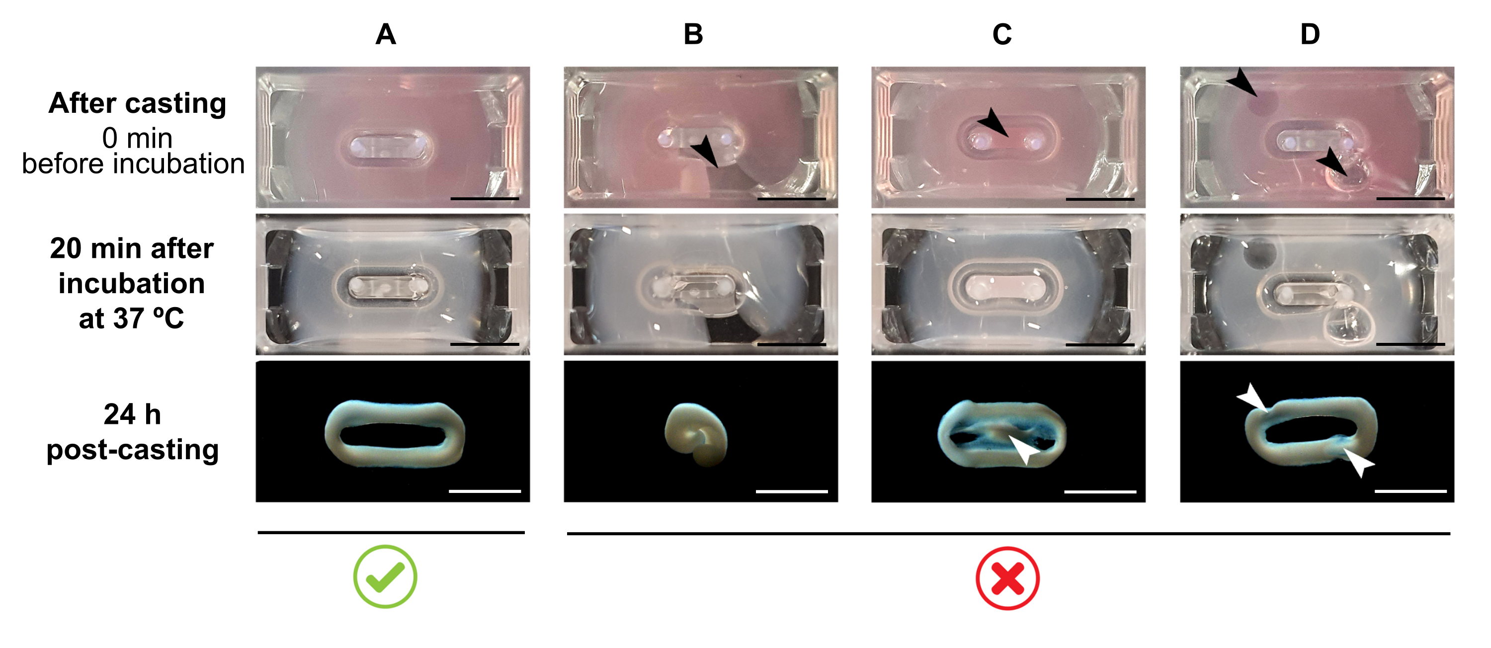
NOTE: The recommended casting volume is 180 µL, but it can be extended to 200 µL38. Therefore, when preferred, volumes in Table 2 can be adapted to 200 µL in a manner that keeps the same concentrations and ratio between cells and collagen.- Ensure that a complete loop is formed within the mold (Figure 3A). If the ECT hydrogel mixture is applied discontinuously, a complete ECT ring formation will be prevented (Figure 3B).
- Avoid pipetting into the inner well (Figure 3C) and the formation of bubbles during pipetting (Figure 3D), to ensure a homogeneous and functional tissue formation.

Figure 3: Casting, hydrogel formation, and ECT condensation in multi-well format. The top panels exemplify the appearance of ECT directly after casting. The middle panels exemplify the appearance of ECT after incubation for 20 minutes at 37 °C. The bottom panels exemplify the state of compaction of ECT 24 h after preparation, removed from the poles. (A) Proper ECT formation between two poles during the first 24 h. (B-D) Examples of pipetting errors that prevent proper ECT formation. The white and black arrows point to structural defects of ECT due to improper casting. Scale bar: 5 mm. Please click here to view a larger version of this figure.
- Carefully place the 48-well casting plate inside the cell culture incubator and let the ECT hydrogel mixture reconstitute for 15-30 min. After incubation, it will appear gel-like and opaque (Figure 3, middle panel).
- Add 600 µL of 37 °C warm FGM per well, without pipetting the culture medium directly onto the forming ECT as this can result in tissue disruption. Gently add the culture medium along the well wall, as at this point, the ECT must also not be detached from the bottom (Figure 4).

Figure 4: Proper and improper addition of culture medium to the freshly cast ECT. (A) While adding the culture medium after initial ECT solidification (20 min after casting), the condensing ECT must be left undisturbed at the bottom of the well. During the next 24 h, cell-driven matrix compaction will make the ECT slide up the ramp. The final ECT position is controlled by concave cavities at a defined pole height; this ensures that all ECT settle at the same position to allow for a comparison of pole bending activity in parallel ECT culture. (B) Forming ECT detached from the bottom while adding the culture medium too rapidly. Floating ECT will compact at the upper culture medium level. Pole contracting forces will not be directly comparable if ECT settle at different positions. Scale bar: 2 mm. Please click here to view a larger version of this figure.
- Incubate for 24 h.
- Replace the medium every day thereafter, with 500 µL of FGM until analysis.
NOTE: After the initial phase of cell-independent gelation, the human CF starts to further compact the ECT hydrogel mixture. Within 24 h, ECT should appear notably compacted and raised to the level where it is held on the flexible poles (Figure 3 and Figure 4A).
4. Assessing ECT compaction by measuring cross-sectional area (CSA) (5 min per ECT).
NOTE: Tissue compaction starts immediately after the collagen assembly and is particularly significant during the first hours. Compaction describes changes mainly triggered by cell-driven compression of the matrix perpendicularly to the tissue's long axis. This parameter is assessed by determining the cross-sectional area (CSA) of the ECT.
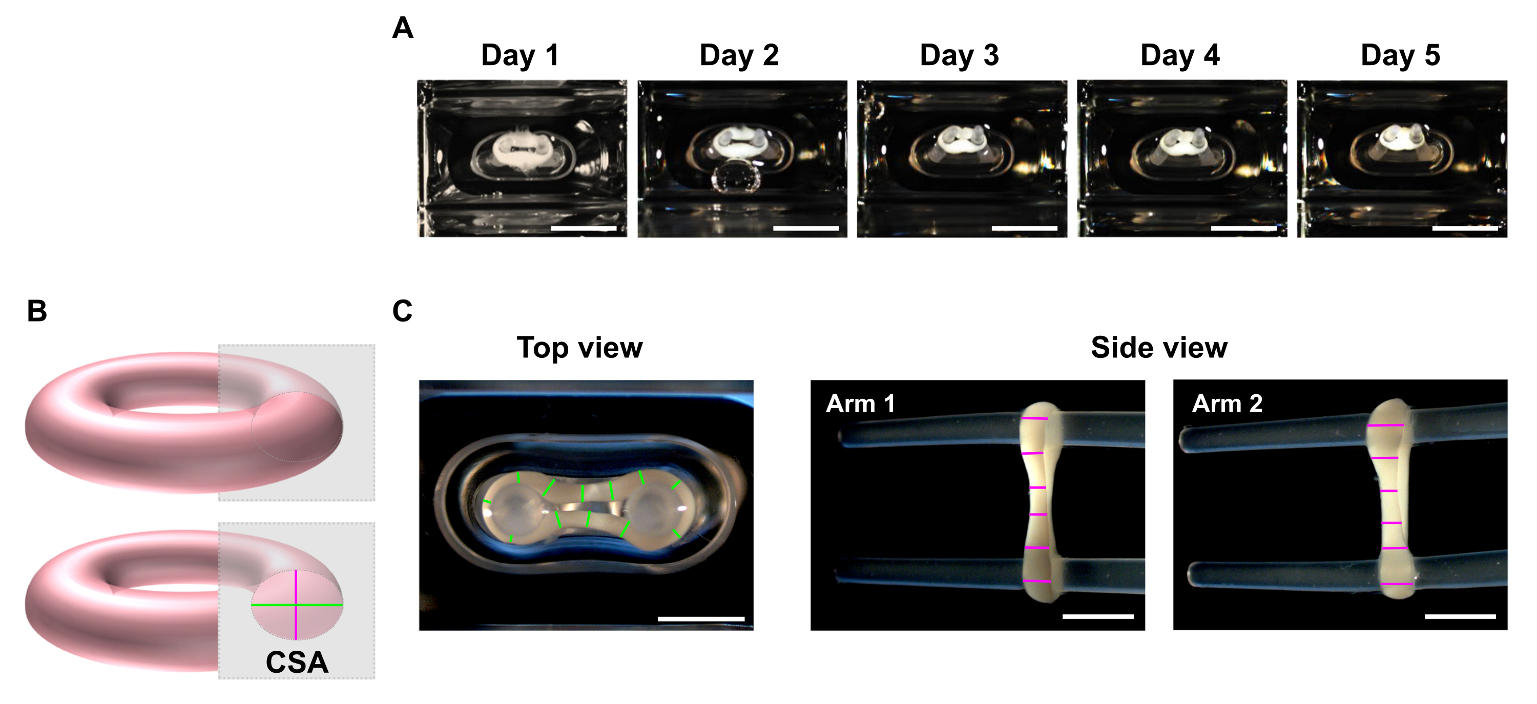
- At the desired time points, use a stereo microscope to record macroscopic images of the top and side views of the ECT (Figure 5C).
NOTE: ECT can be imaged inside of the culturing wells of the 48-well casting plate. Alternatively, transfer the ECT to a clear bottom multi-well plate for imaging. It is advised to image the ECT on the poles as removing those leads to the loss of preload, and consequently, within a short period, the tissue can further contract with eventual torsion due to tension release, which may hamper proper imaging for dimensions' analyses. - Use an image processing program to perform a line scan analysis. Set a scale and use the Straight Line tool to trace and measure the ECT diameters at a minimum of 6 positions per arm in each imaging plane (Figure 5B,C).
- Calculate the mean diameter from top and side view planes and calculate CSA according to an elliptic area equation:


Figure 5: Monitoring ECT compaction over time by cross-sectional area (CSA) analysis. ECT were generated using human CF and collagen type I and cultured around two flexible poles for 5 days. (A) Representative images of control ECT placed in flexible molds over a time of 5 days are presented. Scale bar = 5 mm. Such bright-field images can also be used to determine pole deflection variation for estimating tissue contraction. (B) Schematic representation of the cross-sectional area of an ECT (top view diameter in green and side view diameter in pink). (C) Macroscopic images of top and side views of an ECT obtained with a stereomicroscope and correspondent example of line scan analysis of the tissues' diameters using an image processing program. Scale bar = 2 mm. Averaged diameters are calculated from the mean of all line lengths measured on each view plan. Please click here to view a larger version of this figure.
5. Monitoring ECT contraction by pole deflection analysis (15 min per 48-well casting plate).
NOTE: ECT culture is typically performed for 5 days, but it can be further extended at least up to 20 days. Pole deflection occurs due to the tissue contraction driven by the cell contraction force in the direction of tension along the tissue's long axis. Assessment of ECT contraction can be performed by imaging on any day during culture.
- Image the 48-well casting plate under a recording device with an integrated area scan camera placed at a fixed distance, equipped with a high resolution (≥ 5 mega-pixels) monochrome image sensor.
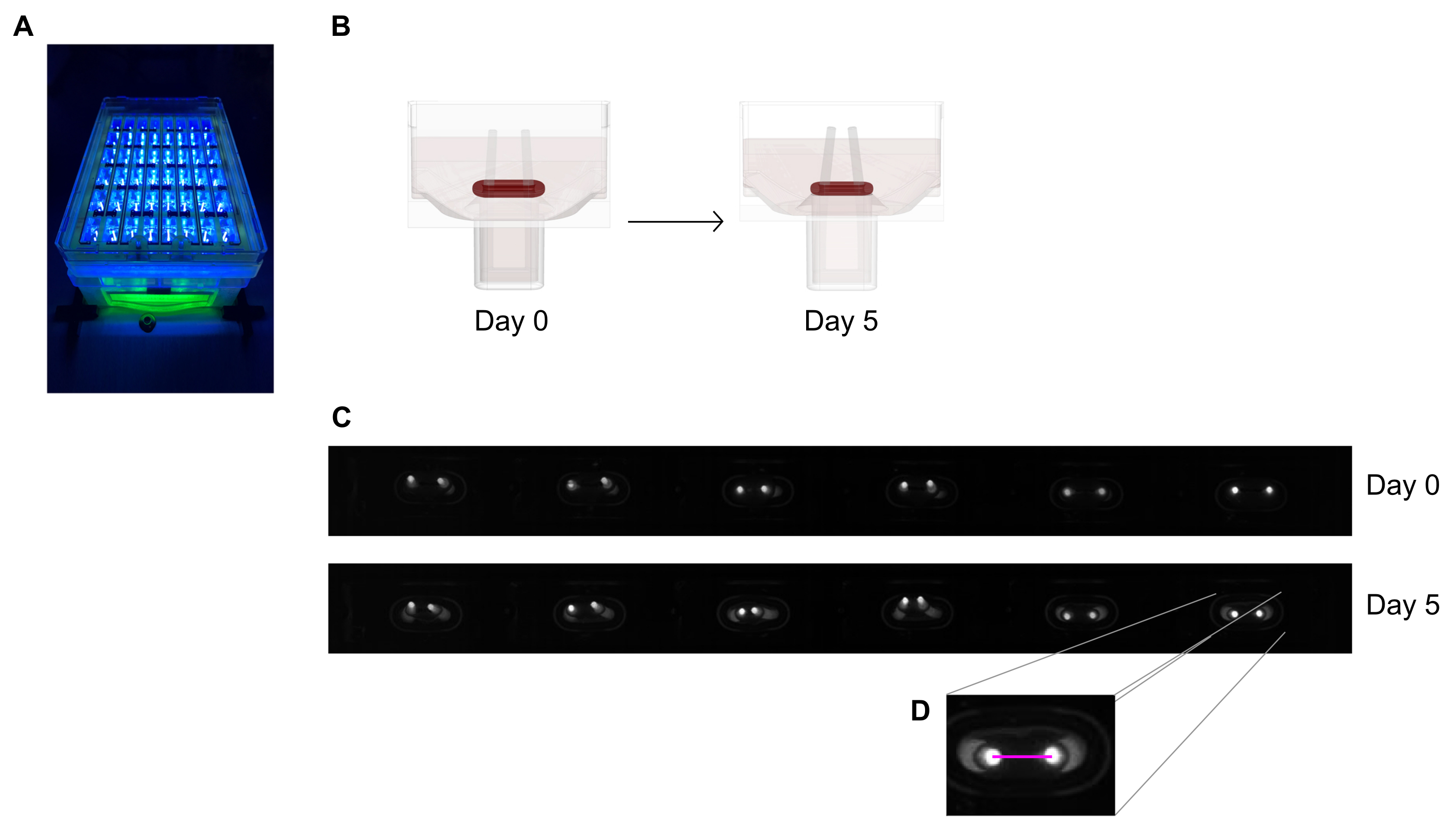
- Use a near-UV (~390 nm) light source to maximize the contrast and thus facilitate automated detection of the poles' tips as they contain a fluorescent dye (Figure 6A,C). If available, telecentric lenses are recommended for imaging as they minimize image distortions.
NOTE: Alternatively, macroscopic bright-field images from single wells or of the complete plate accompanied by a scale bar can be used for the analysis (Figure 5A).
- Use a near-UV (~390 nm) light source to maximize the contrast and thus facilitate automated detection of the poles' tips as they contain a fluorescent dye (Figure 6A,C). If available, telecentric lenses are recommended for imaging as they minimize image distortions.
- Measure the distance between the poles from daily records (Figure 6C,D) using an image processing program or automated analysis by running recorded images on software able to detect high contrast bright pixels on a dark background.
- Calculate the pole deflection through the variation of poles' distance when compared to the initial distance at day zero.

Figure 6: Schematic overview of the assessment of tissue contraction according to pole deflection. (A) Exemplary high-resolution recording of fluorescent poles in the 48-well casting plate under near-UV light excitation. This method is preferred over bright-field pictures for more precise pole tip automated tracing.(B) The schematic drawings demonstrate how ECT compaction and contraction leads to pole bending. (C) An exemplary row of the same plate records at day 0 and day 5 after casting. D. The close up shows how to measure the distance (pink line) between the poles using an image processing program. Please click here to view a larger version of this figure.
NOTE: Consider that pole deflection measured by bright tip image is only an estimative of the tissue contraction due to the difference in imaging planes. Also, note that the application of pro-fibrotic substances such as TGF-β1 during tissue culture enhances ECT compaction and contraction and can ultimately lead to early tissue disruption.
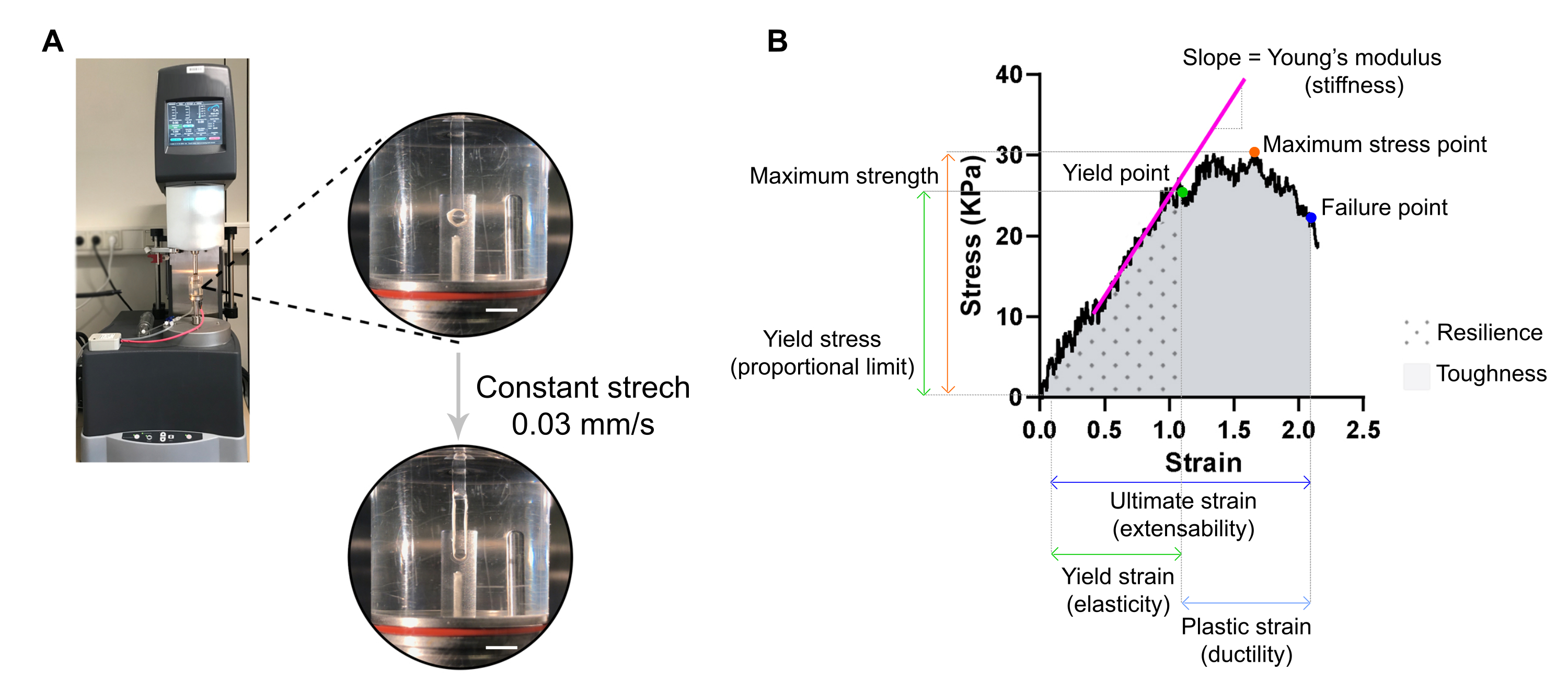
6. Assessment of stiffness and other biomechanical properties of ECT by destructive tensile measurement and stress-strain analysis (20 min per ECT)
NOTE: An optimal stress-strain curve can display three regions: toe region, elastic region, and plastic region. An ECT stress-strain curve example is shown in Figure 7. The analysis of a stress-strain curve allows extracting important biomechanical parameters of the tissue such as e.g., stiffness, maximum strength, elasticity, plasticity, extensibility, resilience, and toughness.
- Harvest ECT by first pulling the stretcher, including ECT, out of its well, using forceps. The stretcher can then be held on its base, and the ECT slipped over the stretcher tips using a fine hook or pipette tip.
- Transfer the ECT onto two hooks clamped to the stationary arm and the transducer arm of an extensional dynamic mechanical analysis (DMA) rheometer equipped with a 37 °C tempered organ bath (custom-made) filled with PBS (Figure 7A).

Figure 7: ECT destructive tensile measurement analysis. (A) Rheological destructive tensile measurement on an extensional dynamic mechanical analysis (DMA) rheometer. Upper high power view: ECT after mounting at L0 in an environmental chamber and connected to an upper and lower pole for stress-strain analyses. Bottom high power view: ECT strained at a constant rate 0.03 mm/s until the failure point at ultimate strain. Scale bars = 5 mm. (B) Stress-strain diagram of an ECT showing the main measured parameters. The upper limit of the elastic region corresponds to the yield point and the plastic region is comprised between the yield point and the failure point (ductility). The slope of the linear phase of the elastic region corresponds to the Young's modulus reflecting tissue stiffness. The maximum strength corresponds to the maximum tensile stress a tissue can withstand. Due to fiber microfracturing, the stress decreases until the tissue reaches the failure point. This occurs at the ultimate strain (extensibility) where a sudden drop in stress is observed due to the rupture of the tissue. Resilience corresponds to the energy (kJ/m3) absorbed by the tissue before permanent deformation (up to the yield point) and is given by the area under the curve (AUC) up to the yield point strain. Toughness corresponds to the total energy (kJ/m3) the tissue can absorb until rupture and is given by the AUC up to the ultimate strain. Please click here to view a larger version of this figure.
- Set the rheometer to apply uniaxial tension at a constant linear rate of approximately 1 % of the initial distance between the hooks per second. A constant stretching rate of 0.03 mm/s can be used with the typical ECT dimensions. Tare the transducer, initiate the stretch and record until the point of ECT rupture.
CAUTION: Macroscopic pictures of ECT (step 4.1.) must be recorded before tensile testing, as the CSA is required for data normalization.
NOTE: The stress-strain analysis, including CSA calculation, can be processed later in time upon tensile testing. Use a spreadsheet software and a statistical analysis software for analyzing the data. - Normalize measured force values (mN) per ECT by its CSA (mm2) to obtain stress values (kPa).
- Plot stress values against strain (a geometric measure of tissue deformation given by the relative distance between the upper and lower hook) on a XY graph.
NOTE: The initial length of the tissue (distance between the upper and lower hook) immediately before the stretch ensues, L0, must be manually adjusted and corresponds to the beginning of the toe region (toe region can be absent depending on tissue properties). Each strain point value must be calculated according to the equation, in which Ltotal is the total gap at every measuring point:

When plotting the data, use the stress value at selected L0 for background subtraction. - Determine different biomechanical parameters from the stress-strain curve (use Figure 7B as an example).
NOTE: A stress-strain curve can display three regions: toe, elastic, and plastic regions. The upper limit of the elastic region, before the tissue starts microfracturing, corresponds to the yield point, and its strain is a measure of tissue elasticity. The plastic region is comprised between the yield point and the failure point. The later point corresponds to a sudden drop in stress due to the rupture of the tissue, defining the ultimate stain, which is a measure of tissue extensibility. The third measuring point corresponds to the maximum strength, which is defined by the highest stress that the tissue can bear without breaking during the stretch. The resilience and toughness, given by the area under the curve, corresponds to the energy absorbed by the tissue up to the yield point and to the failure point, respectively. For each obtained curve, the slope of the linear part of the elastic region corresponds to the Young's modulus, also known as elastic modulus, and is a mechanical property that measures the stiffness of the tissue.- Extract from each curve the XY values (strain and stress, respectively) of the yield point, failure point, and maximum stress point.
- Assess the Young's modulus (stiffness in kPa = mN·mm-2) of each ECT from the slope of the linear part of the elastic region by plotting a linear regression of that region.
- Use a statistical program to compute the area under the curve (AUC) to determine both resilience and toughness, up to the yield point and the failure point, respectively. Compute AUC by the trapezoidal method. Set the baseline to zero and consider only the peaks above the baseline, which are at least 10 % of the distance from the minimum to the maximum value in the Y-axis.
NOTE: The moduli of resilience and toughness are given by σ × ε, where σ is stress (kPa) and ε is the strain (L/ΔL, mm/mm). Thus, resilience and toughness are the energy in kJ/m3 (kPa = kN·m-2 = kN·m·m-3 = kJ/m·m·m-3 = kJ/m3) absorbed by the tissue before permanent deformation and until rupture, respectively.
Wyniki
ECT reach around 95 % compaction compared to the initial cell-collagen hydrogel volume within the first 24 h. Tissue compaction and contraction under control conditions and in the presence of FCS ensues a few hours after casting and notably increases up to day 5 (Figure 5A). Pole deflection may further increase during the following 15 days (20 days was the longest time tested). The magnitude of pole deflection depends on cell type, cell state, and cell and tissue culture conditions. Typicall...
Dyskusje
The presented protocol describes the generation of ECT from primary human CF, which allows studying the mechanical impact of these cells on their extracellular matrix environment and vice-versa.
The fibroblasts need to be expanded to yield sufficient cells for the planned ECT experiments (0.75 x 10⁶ cells/ECT). For the best reproducibility, it is advised to pre-culture frozen or tissue-derived fibroblasts in 2D monolayer culture for a standardized duration up to 80 % confluency with...
Ujawnienia
GLS and SL drafted the manuscript. All authors contributed to the protocol development and edited the manuscript. TM, MT, and WHZ are scientific advisors to myriamed GmbH. WHZ is the founder and shareholder of myriamed GmbH.
Podziękowania
This work was supported by the German Cardiac Society (DGK Research Fellowship for GLS) and by the German Research Foundation (DFG through the project IRTG 1816 for GLS and AD; DFG 417880571 and DFG TI 956/1-1 for MT; SFB 1002 TP C04 for MT and WHZ; SFB 1002 TP S01 for WHZ; and EXC 2067/1-390729940J for WHZ). WHZ is supported by the German Federal Ministry for Science and Education (BMBF through the project IndiHEART), and the Fondation Leducq (20CVD04). MT, WHZ and SL are supported by the German Center for Cardiovascular Research (DZHK).
Materiały
| Name | Company | Catalog Number | Comments |
| Cell culture reagents: | |||
| Accutase Solution | Merk Millipore | SCR005 | |
| Dissociation reagent – TrypLE Express | Gibco | 12604013 | |
| Dulbecco's Modified Eagle Medium (DMEM) powder, high glucose | Gibco | 12100061 | |
| Dulbecco’s phosphate buffered saline (DPBS), pH 7.2, -Ca2+, -Mg2+ | Gibco | 14190144 | |
| FGM-2 Fibroblast Growth Medium-2 BulletKit | Lonza | CC-3132 | |
| FBM Fibroblast Growth Basal Medium | Lonza | CC-3131 | |
| FGM-2 Fibroblast Growth Medium-2 SingleQuots, Supplements and Growth Factors | Lonza | CC-4126 | |
| Fibroblast Growth Medium 3 KIT | PromoCell | C-23130 | |
| Fibroblast Basal Medium 3 | PromoCell | C-23230 | |
| Growth Medium 3 SupplementPack | PromoCell | C-39350 | |
| Penicillin (10000 U/mL)/ Streptomycin (10000 μL/mL) | Gibco | 15140122 | |
| Sodium hydroxide solution (NaOH) 1.0 N | Sigma-Aldrich | S2770-100ML | |
| Cell sources: | |||
| Normal human cardiac fibroblasts from the ventricle (NHCF-V) | Lonza | CC-2904 | |
| Human Cardiac Fibroblasts (HCF-c) | PromoCell | C-12375 | |
| Human Cardiac Fibroblasts (HCF-p) | PromoCell | C-12377 | |
| Primary human foreskin fibroblasts-1 (HFF-1) | ATCC | SCRC- 1041 | |
| Collagen sourses: | |||
| Collagen Type I (bovine) in 0.01 M HCl | LLC Collagen Solutions | FS22024 | 6-7 mg/mL |
| Collagen Type I (rat tail) in 0.02 M HCl | Corning | 354236 | ~4 mg/mL |
| Drugs: | |||
| Latrunculin-A (Lat-A) | Enzo Life Sciences | BML-T119-0100 | |
| Plastic ware: | |||
| Cell culture plastic ware | Sarstedt and Starlab | ||
| Mesh cell strainer (Nylon, pore size 40 μm) | Falcon | 352340 | |
| myrPlate-uniform | myriamed GmbH | TM5 med | |
| Serological pipettes wide opening, sterile (10 mL) | Corning | 07-200-619 | |
| Specific instruments: | |||
| Bi-telecentric CORE lens for 1/2″ detectors | OptoEngineering | TCCR12096 | |
| Area scan camera Basler ace acA4024 | Basler | 107404 |
Odniesienia
- Driesen, R. B., et al. Reversible and irreversible differentiation of cardiac fibroblasts. Cardiovascular Research. 101 (3), 411-422 (2014).
- Shi, X., et al. Elasticity of cardiac cells on the polymer substrates with different stiffness: an atomic force microscopy study. Physical Chemistry Chemical Physics. 13 (16), 7540-7545 (2011).
- Elson, E. L., Genin, G. M. Tissue constructs: platforms for basic research and drug discovery. Interface Focus. 6 (1), 20150095 (2016).
- Cho, N., Razipour, S. E., McCain, M. L. TGF-beta1 dominates extracellular matrix rigidity for inducing differentiation of human cardiac fibroblasts to myofibroblasts. Experimental Biology and Medicine. 243 (7), 601-612 (2018).
- Cucoranu, I., et al. NAD(P)H oxidase 4 mediates transforming growth factor-beta1-induced differentiation of cardiac fibroblasts into myofibroblasts. Circulation Research. 97 (9), 900-907 (2005).
- Peng, H., Carretero, O. A., Peterson, E. L., Rhaleb, N. E. Ac-SDKP inhibits transforming growth factor-beta1-induced differentiation of human cardiac fibroblasts into myofibroblasts. American Journal of Physiology-Heart and Circulatory Physiology. 298 (5), 1357-1364 (2010).
- Ribeiro, A. J., et al. Contractility of single cardiomyocytes differentiated from pluripotent stem cells depends on physiological shape and substrate stiffness. Proceedings of the National Academy of Sciences of the United States of America. 112 (41), 12705-12710 (2015).
- Tranquillo, R. T., Durrani, M. A., Moon, A. G. Tissue engineering science: consequences of cell traction force. Cytotechnology. 10 (3), 225-250 (1992).
- Barocas, V. H., Moon, A. G., Tranquillo, R. T. The fibroblast-populated collagen microsphere assay of cell traction force--Part 2: Measurement of the cell traction parameter. Journal of Biomechanical Engineering. 117 (2), 161-170 (1995).
- Lijnen, P., Petrov, V., Rumilla, K., Fagard, R. Stimulation of collagen gel contraction by angiotensin II and III in cardiac fibroblasts. Journal of the Renin-Angiotensin-Aldosterone System. 3 (3), 160-166 (2002).
- Baxter, S. C., Morales, M. O., Goldsmith, E. C. Adaptive changes in cardiac fibroblast morphology and collagen organization as a result of mechanical environment. Cell Biochemistry and Biophysics. 51 (1), 33-44 (2008).
- Zhou, Y., et al. Inhibition of mechanosensitive signaling in myofibroblasts ameliorates experimental pulmonary fibrosis. Journal of Clinical Investigation. 123 (3), 1096-1108 (2013).
- Lijnen, P., Petrov, V., Fagard, R. In vitro assay of collagen gel contraction by cardiac fibroblasts in serum-free conditions. Methods and Findings in Experimental and Clinical Pharmacology. 23 (7), 377-382 (2001).
- Burgess, M. L., et al. Integrin-mediated collagen gel contraction by cardiac fibroblasts. Effects of angiotensin II. Circulation Research. 74 (2), 291-298 (1994).
- Nunohiro, T., Ashizawa, N., Graf, K., Hsueh, W. A., Yano, K. Angiotensin II promotes integrin-mediated collagen gel contraction by adult rat cardiac fibroblasts. Japanese Heart Journal. 40 (4), 461-469 (1999).
- Ngu, J. M., et al. Human cardiac fibroblast extracellular matrix remodeling: Dual effects of tissue inhibitor of metalloproteinase-2. Cardiovascular Pathology. 23 (6), 335-343 (2014).
- Knezevic, V., Sim, A. J., Borg, T. K., Holmes, J. W. Isotonic biaxial loading of fibroblast-populated collagen gels: a versatile, low-cost system for the study of mechanobiology. Biomechanics and Modeling in Mechanobiology. 1 (1), 59-67 (2002).
- Delvoye, P., Wiliquet, P., Leveque, J. L., Nusgens, B. V., Lapiere, C. M. Measurement of mechanical forces generated by skin fibroblasts embedded in a three-dimensional collagen gel. Journal of Investigative Dermatology. 97 (5), 898-902 (1991).
- Kolodney, M. S., Elson, E. L. Correlation of myosin light chain phosphorylation with isometric contraction of fibroblasts. Journal of Biological Chemistry. 268 (32), 23850-23855 (1993).
- Bell, B. J., Nauman, E., Voytik-Harbin, S. L. Multiscale strain analysis of tissue equivalents using a custom-designed biaxial testing device. Biophysical Journal. 102 (6), 1303-1312 (2012).
- Wakatsuki, T., Kolodney, M. S., Zahalak, G. I., Elson, E. L. Cell mechanics studied by a reconstituted model tissue. Biophysical Journal. 79 (5), 2353-2368 (2000).
- Thomopoulos, S., et al. Fibrocartilage tissue engineering: The role of the stress environment on cell morphology and matrix expression. Tissue Engineering Part A. 17 (7-8), 1039-1053 (2011).
- Roeder, B. A., Kokini, K., Sturgis, J. E., Robinson, J. P., Voytik-Harbin, S. L. Tensile mechanical properties of three-dimensional type I collagen extracellular matrices with varied microstructure. Journal of Biomechanical Engineering. 124 (2), 214-222 (2002).
- Ongherth, A., et al. p63RhoGEF regulates auto- and paracrine signaling in cardiac fibroblasts. Journal of Molecular and Cellular Cardiology. 88, 39-54 (2015).
- Vettel, C., et al. PDE2-mediated cAMP hydrolysis accelerates cardiac fibroblast to myofibroblast conversion and is antagonized by exogenous activation of cGMP signaling pathways. American Journal of Physiology-Heart and Circulatory Physiology. 306 (8), 1246-1252 (2014).
- Jatho, A., et al. RhoA Ambivalently Controls Prominent Myofibroblast Characteritics by Involving Distinct Signaling Routes. PLoS One. 10 (10), 0137519 (2015).
- Dworatzek, E., et al. Sex-specific regulation of collagen I and III expression by 17beta-Estradiol in cardiac fibroblasts: role of estrogen receptors. Cardiovascular Research. 115 (2), 315-327 (2019).
- Tiburcy, M., Meyer, T., Soong, P. L., Zimmermann, W. H. Collagen-based engineered heart muscle. Methods in Molecular Biology. 1181, 167-176 (2014).
- Schlick, S. F., et al. Agonistic and antagonistic roles of fibroblasts and cardiomyocytes on viscoelastic stiffening of engineered human myocardium. Progress in Biophysics and Molecular Biology. 144, 51-60 (2019).
- Wille, J. J., Elson, E. L., Okamoto, R. J. Cellular and matrix mechanics of bioartificial tissues during continuous cyclic stretch. Annals of Biomedical Engineering. 34 (11), 1678-1690 (2006).
- Berry, C. C., Shelton, J. C., Bader, D. L., Lee, D. A. Influence of external uniaxial cyclic strain on oriented fibroblast-seeded collagen gels. Tissue Engineering. 9 (4), 613-624 (2003).
- Stopak, D., Harris, A. K. Connective tissue morphogenesis by fibroblast traction. I. Tissue culture observations. Developmental Biology. 90 (2), 383-398 (1982).
- Bellows, C. G., Melcher, A. H., Aubin, J. E. Association between tension and orientation of periodontal ligament fibroblasts and exogenous collagen fibres in collagen gels in vitro. Journal of Cell Science. 58 (1), 125-138 (1982).
- Tranquillo, R. T. Self-organization of tissue-equivalents: the nature and role of contact guidance. Biochemical Society Symposia. 65, 27-42 (1999).
- Barocas, V. H., Tranquillo, R. T. An anisotropic biphasic theory of tissue-equivalent mechanics: the interplay among cell traction, fibrillar network deformation, fibril alignment, and cell contact guidance. Journal of Biomechanical Engineering. 119 (2), 137-145 (1997).
- Yip, A. K., et al. Anisotropic traction stresses and focal adhesion polarization mediates topography-induced cell elongation. Biomaterials. 181, 103-112 (2018).
- Santos, G. L., Hartmann, S., Zimmermann, W. H., Ridley, A., Lutz, S. Inhibition of Rho-associated kinases suppresses cardiac myofibroblast function in engineered connective and heart muscle tissues. Journal of Molecular and Cellular Cardiology. 134, 13-28 (2019).
- Kittana, N., et al. Modulating the biomechanical properties of engineered connective tissues by chitosan-coated multiwall carbon nanotubes. International Journal of Nanomedicine. 16, 989-1000 (2021).
- Kittana, N., et al. Enhancement of wound healing by single-wall/multi-wall carbon nanotubes complexed with chitosan. International Journal of Nanomedicine. 13, 7195-7206 (2018).
- Antoine, E. E., Vlachos, P. P., Rylander, M. N. Review of collagen I hydrogels for bioengineered tissue microenvironments: characterization of mechanics, structure, and transport. Tissue Engineering Part B: Reviews. 20 (6), 683-696 (2014).
- Holder, A. J., et al. Control of collagen gel mechanical properties through manipulation of gelation conditions near the sol-gel transition. Soft Matter. 14 (4), 574-580 (2018).
- Zimmermann, W. H., et al. Tissue engineering of a differentiated cardiac muscle construct. Circulation Research. 90 (2), 223-230 (2002).
Przedruki i uprawnienia
Zapytaj o uprawnienia na użycie tekstu lub obrazów z tego artykułu JoVE
Zapytaj o uprawnieniaPrzeglądaj więcej artyków
This article has been published
Video Coming Soon
Copyright © 2025 MyJoVE Corporation. Wszelkie prawa zastrzeżone