A subscription to JoVE is required to view this content. Sign in or start your free trial.
Method Article
The Xenopus Oocyte Cut-open Vaseline Gap Voltage-clamp Technique With Fluorometry
In This Article
Summary
The cut-open Vaseline gap approach is used to obtain low noise recordings of ionic and gating currents from voltage-dependent ion channels expressed in Xenopus oocytes with high resolution of fast channel kinetics. With minor modification, voltage clamp fluorometry can be coupled to the cut-open oocyte protocol.
Abstract
The cut-open oocyte Vaseline gap (COVG) voltage clamp technique allows for analysis of electrophysiological and kinetic properties of heterologous ion channels in oocytes. Recordings from the cut-open setup are particularly useful for resolving low magnitude gating currents, rapid ionic current activation, and deactivation. The main benefits over the two-electrode voltage clamp (TEVC) technique include increased clamp speed, improved signal-to-noise ratio, and the ability to modulate the intracellular and extracellular milieu.
Here, we employ the human cardiac sodium channel (hNaV1.5), expressed in Xenopus oocytes, to demonstrate the cut-open setup and protocol as well as modifications that are required to add voltage clamp fluorometry capability.
The properties of fast activating ion channels, such as hNaV1.5, cannot be fully resolved near room temperature using TEVC, in which the entirety of the oocyte membrane is clamped, making voltage control difficult. However, in the cut-open technique, isolation of only a small portion of the cell membrane allows for the rapid clamping required to accurately record fast kinetics while preventing channel run-down associated with patch clamp techniques.
In conjunction with the COVG technique, ion channel kinetics and electrophysiological properties can be further assayed by using voltage clamp fluorometry, where protein motion is tracked via cysteine conjugation of extracellularly applied fluorophores, insertion of genetically encoded fluorescent proteins, or the incorporation of unnatural amino acids into the region of interest1. This additional data yields kinetic information about voltage-dependent conformational rearrangements of the protein via changes in the microenvironment surrounding the fluorescent molecule.
Introduction
Specialized voltage clamping techniques permit the recording of ionic currents at controlled membrane potentials. Widely used two-electrode voltage clamp (TEVC) and patch clamp techniques provide reliable electrophysiological information on the properties of many ion channels. However, both of these methods have drawbacks that prevent the acquisition of reliable data for fast voltage-gated sodium channels and other fast activating channels in membranes such as those of Xenopus oocytes. The Bezanilla and Stefani laboratories consequently developed the cut-open Vaseline gap voltage clamp technique (COVG) for oocytes2. The technique has been applied widely to record, Na+, K+, and Ca2+ channels3-8.
During COVG recording, a heterologous protein-expressing oocyte membrane is divided into three regions. The ionic current data is recorded from the top region of the oocyte as the bath surrounding the top region is clamped to a command potential, which can be easily and quickly changed. The middle region guards against leakage currents by being clamped to the same potential as the top region9. The bottom region is where oocyte opening (cut-open) occurs through the use of a saponin solution or a cannula. Chemical or manual opening of the membrane in the bottom region allows control of the internal potential, which is clamped to ground, and renders the cell interior contiguous with the lower chamber solution. Perfusion of solutions into the lower chamber can adjust the properties of the internal environment, whereas solution exchange in the top chamber alters the external surroundings.

Figure 1. Oocyte Cut-Open Voltage-Clamp Bath Setup Diagram. (A) Top down view of the three baths separated from each other. The dimensions of the chambers for COVG are displayed on the figure. (B) Side view of the baths setup in testing position. Click here to view larger image.
The advantages of the COVG technique include low current noise (1 nA at 3 kHz), control of the ionic composition of the external media, the ability to modulate the internal media, fast time resolution (20-100 μsec time constant of decay of the capacity transient), and stable recordings for several hours9. The disadvantages are that it requires specialized equipment and it is more difficult to perform compared to two electrode voltage clamping (TEVC)10.
While the COVG approach requires highly specialized equipment and intricate procedural elements, it can allow for the acquisition of valuable electrophysiological data. This data, such as gating currents with fast kinetics and tail currents4, can be recorded without some of the issues associated with other voltage clamping protocols including channel run-down. Minor modifications to the COVG setup can allow for the use of temperature controllers and voltage clamp fluorometry (VCF). The inclusion of voltage clamp fluorometry elements within the COVG assembly can augment data output by conferring the ability to monitor protein conformational changes while simultaneously recording current11-13.
Protocol
1. Initial Equipment Setup
- Place the stage and the microelectrode manipulator on a vibration-isolation system (e.g. an air table) with a surrounding Faraday cage to prevent electrical and mechanical noise.
- Solder six Ag/AgCl pellets to six-inch lengths of 24 AWG wire. For one of these lengths (to be connected to P1), splice in a second wire to form a "Y". On the ends of each wire solder a gold BNC pin, which is included with the amplifier.
- Connect the five Ag/AgCl pellets soldered to 24 AWG wire to the Bath/Guard headstage (P1, P2, CC, GS1, and GS2). Connect the "I" Ag/AgCl pellet to the "I" headstage and the second wire coming off of P1 to the V2 headstage.
- Connect the amplifier to the data acquisition unit according to the directions in the equipment manuals.
- Place and epoxy the temperature controller thermistors. Thread the block thermistor through a hole in the metal scaffold directly above the center of the heating/cooling element. Place and epoxy the bath thermistor in a hole drilled in the body of the temperature-conducting bottom chamber very close but not contacting the solution.
2. Oocyte and Preliminary Preparation
- To record a heterologously expressed channel such as hNaV1.5, synthesize mRNA (derived from hSCN5a) and inject it into a Xenopus oocyte around 4-5 days before performing Protocol 4. For hSCN5a, peak expression is obtained after incubating for 4-5 days at 19 °C. Refer to Richards and Dempski14 and Cohen et al.15 for detailed instructions on oocyte, mRNA preparation, and oocyte injection.
- Chloride the AgCl wire and AgCl pellets before beginning Protocol 4. To do this, place one end of the wire and the pellets into bleach for at least 20 min and as long as O/N. Once the pellets have been chlorided, affix them to the manifold using adhesive.
Note: Driving current through the wires can also be used to chloride the wire and pellets. This technique will increase the speed of chloridation but also require more equipment. See Techniques for Chloriding Silver Wires for further instruction16.
3. Agar Bridge Preparation
- Make at least six agar bridges by heating up one end of a borosilicate capillary tube in a medium flame. Make sure that the end of the capillary tubing is in the top portion of the blue flame. Make extra bridges in case of damage to the originals.
- Once the capillary tube has heated up, use forceps to make a 90° angle bend in the tube. Aim for a bend with a smooth curvature rather than an abrupt corner or it may significantly reduce the internal diameter of the glass, which makes filling more difficult and increases the resistance of the bridge.
- Make a second 90° bend in the same direction 25 mm down the capillary tube from the first bend using the same steps.
Note: The exact length of the bridge does not matter as long as the bridge size is consistent, but ultimately the lengths should be suitable for the rig they will be used on. Keep in mind that bridge resistance is proportional to its length and should be minimized. - Once the capillary tubes have cooled, use a diamond-tipped glass cutter to trim the "legs" of the bridge to approximately 5 mm.
- Insert lengths of platinum wire into the capillary tubes of the three "current-supplying" bridges to improve performance by reducing resistance in the agar17. Cut off any excess platinum wire so that there is no wire exposed outside the tube.
Note: Due to the high cost of platinum, retrieve and reuse any wire from broken bridges. - Push the platinum wire further into the capillary tube with a fine-tipped implement such as a micropipette tip so that the wire is 1 mm shorter than the glass on both ends of the capillary tube.
- Make 100 ml of 1 M NMDG buffered with 1.2 g of HEPES. Use a pH meter and add MES hydrate powder until a pH of 7.4 is achieved (~10 g). Once a pH of 7.4 has been reached, remove the pH electrode. Set aside 40 ml of the solution to keep as a storage solution.
- Add granulated agar to produce a 2-3% agar mixture. Stir and heat until the agar solution is dissolved and clear. Do not overheat or boil the solution as it will become overly viscous and filling the bridges will be difficult.
- Move the agar solution to a new beaker and add a small stir bar. Continue heating and stirring at a moderate speed.
- Add the capillary bridges one at a time with the legs facing up. Over time the bridges will fill with agar. Alternatively, fill the bridges by pushing agar solution through a syringe attached to a small pipette tip.
- Once there are no bubbles in the bridges, retrieve the bridges from the agar solution and place the bridges on a paper towel to dry. Any bridges with residual bubbles can be agitated with forceps to facilitate bubble exit.
Note: Settled agar with bubbles can be completely removed by immersing the bridges into boiling water. Once the agar is removed, use a vacuum line to remove residual water. Bridges can then be reused for agar treatment. - Remove excess agar from the bridges when dry. Add 60 ml of water to the 40 ml reserve solution and place the bridges in the storage solution.
4. Cut-open Rig Preparation
- Turn on the water source for the temperature controller and then the power switch to the temperature controller. Wait until the bath temperature reaches the specified temperature (19 °C).
- Pull microelectrodes from borosilicate capillary tubing with a microelectrode puller to a resistance of 0.2-0.5 MΩ.
Note: Lowering pipette resistance improves clamping speed. However, lower resistance pipettes are more likely to damage the oocyte. Experimentation is required to determine the best pipette resistance value for each application. - Prepare the saponin solution by mixing 0.125 g of dry saponin with 50 ml of internal solution. This will lead to a 0.25% solution. Invert gently to mix.
- Under a dissecting microscope apply a small amount of Vaseline around the edge of the hole on the top side of the middle chamber and the bottom side of the upper chamber with a very fine-tipped object.
Note: The "donut" of Vaseline will help keep the oocyte in place over the hole and will aid in the formation of the seal. However, too much Vaseline will trap bubbles and prevent the solutions from reaching the oocyte surface. - Add 3 M KCl solution into the manifold slots holding Ag/AgCl pellets so that there is no overflow from the slots but the pellets and bridge leg ends are covered. Clean up extra KCl droplets to prevent unwanted electric connections between slots.
- Add external solution to the lower and middle bath chambers.
- Place the agar bridges into the slots in the AgCl pellet manifold so that one leg per bridge is in each slot. The other leg of the bridges will later be placed into the respective chambers (P1, P2, CC top; GS1,GS2 middle (guard); I bottom). Make sure that platinum wire bridges are in the GS2, P2, and I slots.
Note: Ensure bridges are washed with distilled water and completely dry before inserting into chamber bath. - Turn on the data acquisition system and the PC. Start the recording software.
5. Cut-open Procedure
- Install the top and middle oocyte chambers without an oocyte. Slide the top chamber off-center so that the holes in the two chambers do not overlap. Fill all chambers with external solution and place all the electrodes in their respective chambers.
Note: Do not push the top chamber all the way down when installing the chambers. Make sure a very small gap remains between the two chambers. The off-center arrangement increases the resistance of the chamber system to better simulate the presence of a cell. This process, called "balancing the bridges", compensates for the offset potentials that may arise from inhomogeneity among the agar bridges.- Turn off the external command and both clamps. Check the current reading on the amplifier. Adjust with a small screwdriver the P offset on the back of the bath/guard head-stage to zero current.
- Switch the bath/guard switch on the amplifier to active and adjust the GS offset to obtain zero current.
- Repeat between "active" and "passive" until both are reasonably close to zero (< 100 nA).
- Remove the top chamber and transfer an oocyte into the middle bath chamber using a pipette pump. Make sure the oocyte is positioned over the hole in the center of the bath.
Note: When preparing an oocyte for VCF, place the labeled cell into the chamber with the animal pole (darker side) facing upwards. Cell orientation does not matter if VCF is not being performed. - Remove excess external solution from the bottom bath using an aspirator to create a seal between the oocyte and bath surface.
- Place the top bath chamber over the oocyte so that the hole in the chamber is centered on top of the oocyte. Using a thumb and middle finger, slowly apply pressure down on the chamber until it is pressed tightly against the oocyte so as to expose only a small portion of the membrane to the upper bath through the hole.
Note: The oocyte may bulge under the pressure from the top chamber. Do not apply excessive force to the top chamber, as this will cause the oocyte to rupture. Tweezers tips placed on diagonal corners of the top chamber can be used as an alternative to fingers to apply downward pressure. - Add external solution to the top and bottom baths until they are almost full.
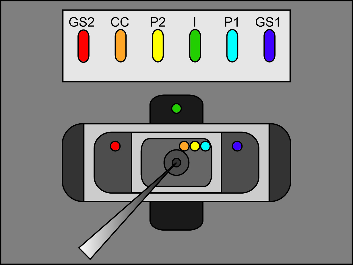
- Place the free legs of the agar bridges into the external solution of each bath as seen in Figure 2 (bridge placement). Make sure that each bridge is resting in its correct bath location. (I bridge in bottom bath, GS1 and GS2 bridges in middle bath, and P1, P2, and CC bridges in upper bath). Switch the bath/guard switch on the amplifier to active.
Note: Ensure there are no 3 M KCl connections between the bridges, their wells, and the recording chambers. Furthermore, make sure bridges are fashioned so that they are raised above the recording chamber solutions.

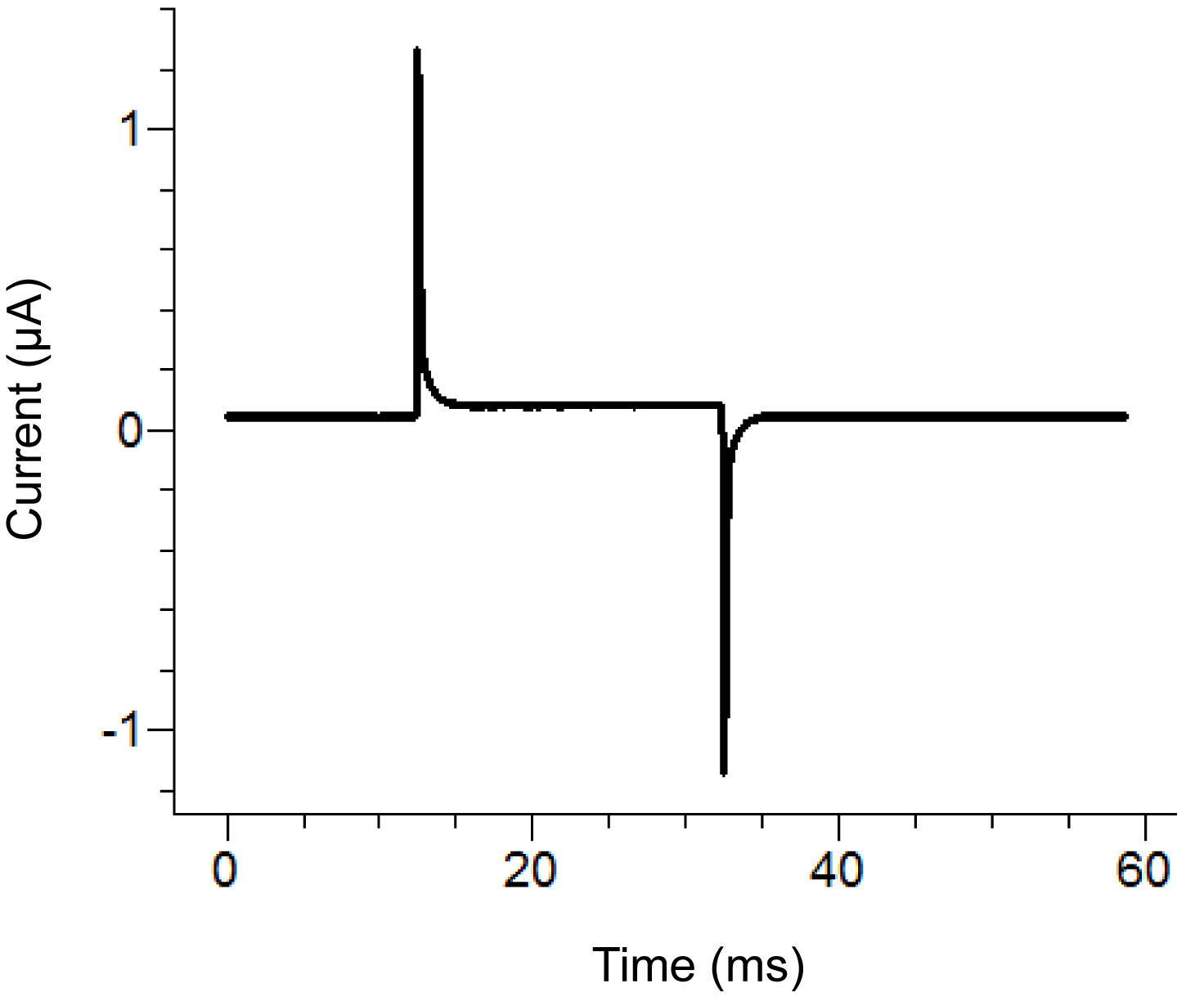
Figure 2. Agar Bridge Setup Location Diagram. Placement locations of the free ends of the agar bridges in the various baths. Click here to view larger image. - Start a test protocol in the recording software. If the pulse shows vertical displacement of the horizontal section between the two peaks upon applying a 100 mV pulse that is greater than 100 nA (corresponding to 0.3 MΩ with the bath/guard in passive) then increase the tightness of the bath cover. See Figure 3 for an example of an ideal test pulse.
Note: The test protocol emits a voltage pulse to see if the bath cover is tight enough and all components have been assembled correctly. Alternatively, the test function of the amplifier can be used.

Figure 3. Ideal Test Pulse from the Recording Software. The test pulse should look similar to the above pulse depending upon the protocol applied. The holding current (center baseline) should be close to zero. Click here to view larger image. - Remove the external solution in the bottom bath and replace with saponin solution. Be careful to avoid creating bubbles while adding the saponin. To ensure maximum replacement, apply suction on the opposite end of the bottom bath while adding the solution.
- After the saponin solution has been added, observe the repeating test pulse. If the peak of the test protocol reduces or disappears then this is a sign that there is a bubble located below the oocyte. In this case, completely remove the saponin solution and then replace it.
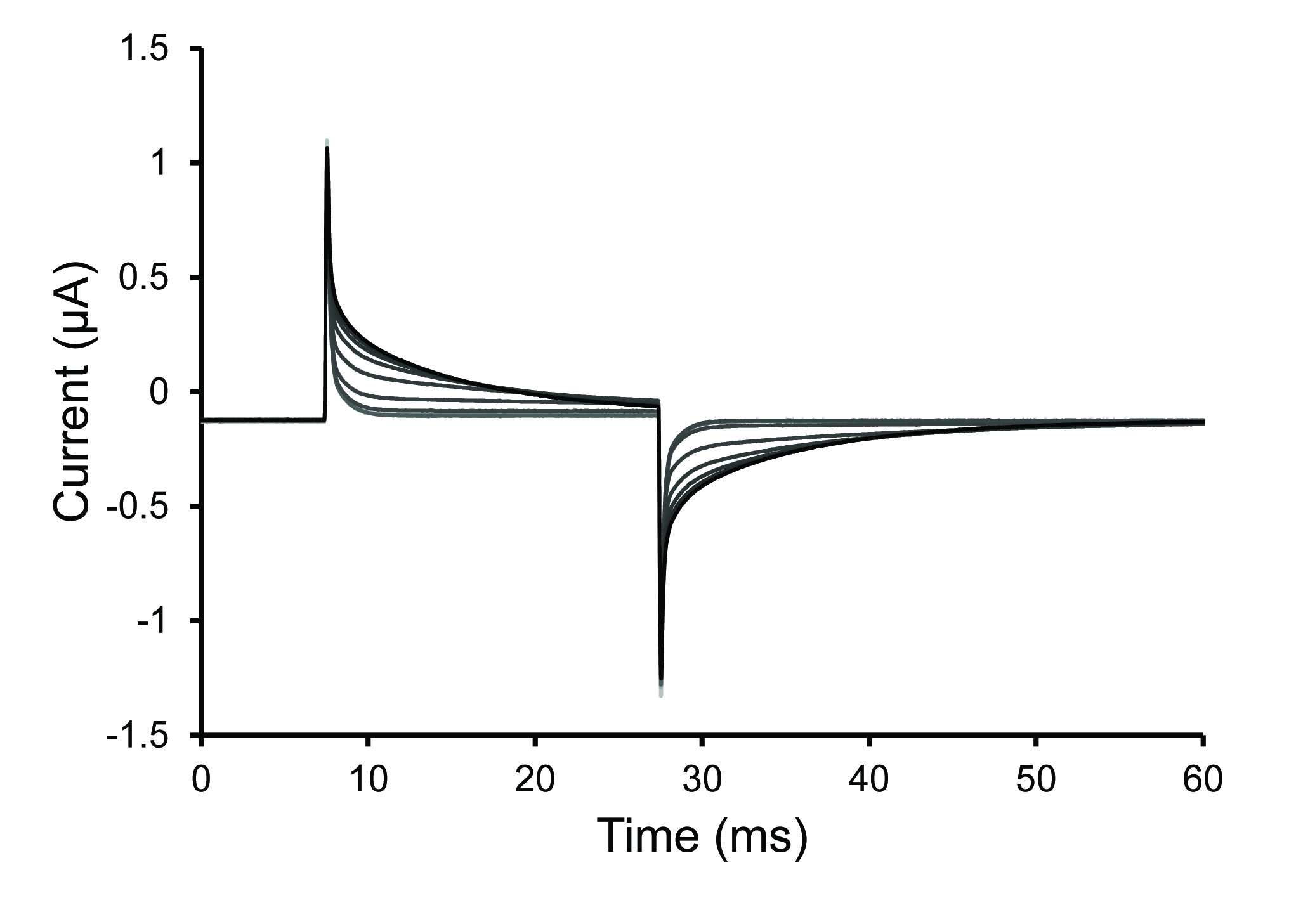
Note: Permeabilization is typically complete within 30 sec with fresh saponin solution. The solutions may have difficulty reaching the cell if there are trapped bubbles or if the follicular layer remains on a poorly digested oocyte. The oocyte has been permeabilized (opened) when the slope of the voltage spike decreases (increase in time constant of decay).

Figure 4. Test Pulse Traces During Oocyte Permeabilization. Selected traces from the test pulse protocol after a 0.25% saponin solution was introduced into the bottom oocyte chamber. The increase of the time constant of decay seen in the traces demonstrates an increase of oocyte permeabilization. Click here to view larger image. - Once the cell is permeabilized, remove the saponin solution and fill the bath with internal solution. Stop the test protocol.
Note: Even though saponin allows access to the interior of the cell by permeabilizing the membrane, equilibration of the ion concentrations between the lower bath and the cytoplasm of the oocyte by diffusion is a very slow process. This process may require tens of minutes depending on conditions (Figure 5). - Check for any high levels of solution in the baths and crystallized KCl between the wells of the manifold as these can cause short circuits and erratic behavior.
- Use the modified syringe to inject 3 M KCl into a microelectrode. Flick the microelectrode several times with one finger while bracing with the other fingers.
Note: This step is required to remove any trapped air bubbles within the microelectrode. - Mount the KCl-filled electrode on the micromanipulator arm by inserting the wire filament into the open microelectrode end. Push the end of the microelectrode into the filament holder and make sure the electrode is not loose. Tighten the electrode fastener.
Note: Make sure that the wire has an even AgCl coating for the electrode to function normally. - Swing the arm into position over the oocyte baths and tighten the clamps to prevent further arm movement.
- Using the manipulator knobs, walk the electrode down into the bath. Make sure that no test pulse is applied and that the membrane test feature is not activated at this point.
Note: Before the electrode tip is inserted into the liquid, V1-V2 on the voltage clamp will read a positive voltage. Once the electrode tip is inserted into the liquid, the voltage meter on the voltage clamp should change to a value close to zero. For VCF recordings, the electrode needs to approach the cell at a fairly shallow angle to leave room for the objective. Impaling the cell with the electrode off-center, closer to the edge of the isolated membrane patch also helps to avoid the collision of the objective with the electrode. - Stop walking the electrode down. Set the electrode offset potential to zero by pressing the V1 button and then reducing the V1 voltage to zero by adjusting the V1 offset. In addition, perform the same adjustment for V2. The potential difference V1-V2 should read 000 mV.
- Switch back to V1 and turn Z-test on to measure electrode resistance. The value will gradually fall and approach the actual resistance. Aim for a resistance value of 0.2-0.5 MΩ.
- Continue walking the electrode down towards the visible patch of the oocyte in the top bath. Once the microelectrode is very close to the oocyte, watch the V1-V2 reading to see when the electrode enters the oocyte; the V1-V2 voltage will become negative when the microelectrode enters the cell.
Note: The value shown at this point is the membrane potential of the cell and will be affected by the channels expressed and the solutions used. Inserting the microelectrode too far will damage the cell membrane. - Open the data collection protocol in the recording software.
- Flip on the clamp switch on the voltage clamp and adjust the potential to match the command (e.g. -100 mV) by adjusting the knob located on the "I" headstage.
- Flip on the capacitance and resistance compensation switch.
- Flip the "Test" switch on in the "Commands" region of the voltage clamp. Use the oscilloscope to visualize the signal. Adjust the Cm compensation knobs in the signal-conditioning segment to reduce the capacitive transients on the oscilloscope. Do not over-compensate the peaks to the point where additional reverse peaks occur or the peaks start to develop a sigmoidal curvature, which can introduce artifact into the recording.
- Once the capacitance has been manually reduced to a satisfactory level, turn off the test switch.
- Commence the data recording protocol in the recording software.
6. Cleanup
- When recordings have been completed, turn off all the various switches on the voltage clamp including the clamp and bath/guard switches.
- Use forceps to remove the agar bridges from the various baths.
- Remove the top bath and aspirate all the solutions and oocyte from all the baths.
- Use a bottle of deionized water to rinse all the baths and then aspirate the baths with a vacuum. Repeat this step 3-5x.
- Wipe crystallized KCl off the bridges and place the bridges in the storage solution. Bridges can be reused for many weeks as long as they are properly stored.
- Aspirate the KCl solution from the manifold wells and rinse the manifold with deionized water several times.
- Turn off all the various equipment including the temperature control and the recording software.
7. Addition of Voltage Clamp Fluorometry
- Follow the steps in Section 1 through 6 in a previously published JoVE protocol16 Examining the Conformational Dynamics of Membrane Proteins in situ with Site-directed Fluorescence Labeling: Click here to view page.
- Perform the steps in Section 4 through 5.22 of the aforementioned COVG protocol using a VCF microscope set at 4X focus.
Note: VCF recordings require larger oocyte bath chambers than required in COVG measurements. (The dimensions of the custom VCF chambers are located in the materials list.) This larger VCF chamber must be capable of simultaneously accommodating the objective lens, microelectrode, and agar bridges. Additionally, the animal pole (dark side of the oocyte) needs to be facing upward in the chamber for low background VCF recordings. - Bring the top portion of the oocyte into focus using a water-immersion 40X objective.
Note: Switching from the 4X to the 40X objective requires a specific geometry of cut-open components and careful attention so as not to hit the electrode, bridges, or chambers when lowering the 40X objective. Furthermore, due to the increased volume in the top guard, ensure that bath volume from the top guard is not connected with the middle guard when the 40X objective is set in place. - Focus on a ring around the perimeter of the exposed oocyte surface, so that the very top of the oocyte is slightly above the plane of focus.
Note: Adjustment in the x-y plane may be necessary so that the field of view is mostly filled with membrane and not the chamber. X-Y translation is most easily accomplished by placement of the microscope on a translation stage. - Move the filter cube into the optical path and switch the light path from the eyepiece to the detector (diode).
- Turn on the VCF light source.
- Turn off the overhead lights, the fiber light illuminator, and other sources of light.
Note: Ideally, VCF recordings should be performed in a completely dark room. - Run a fluorescence protocol in the recording software.
Results
Figure 4 displays the change in permeability of the oocyte as a saponin solution is applied to the bottom section of the oocyte. Figure 5 demonstrates the rate of intracellular solution exchange by diffusion following saponin permeabilization. 20-40 min are required to come to a steady-state2,18.
Figure 6A show traces generated from the recording protocol. The figure shows ionic currents (after P/-8 leak subtraction) in respons...
Discussion
The cut-open oocyte Vaseline gap voltage clamp technique allows for rapid resolution of data, low noise, increased control over internal solution and external solution composition, and stable recordings over relatively long protocols19. These advantages set this technique apart from the standard two-electrode voltage clamp and patch clamp techniques. Although specialized equipment is required and the protocol is relatively difficult, very few issues occur once the system has been optimized. This allows for rep...
Disclosures
The authors have nothing to disclose.
Acknowledgements
All the members of the Washington University in St. Louis Cardiac Molecular Engineering Lab. A Burroughs Welcome Fund Career Award at the Scientific Interface - 1010299 (to J.S.).
Materials
| Name | Company | Catalog Number | Comments |
| External Solution | Brand | Catalog Number | [Final], weight, or volume |
| N-methyl-D-glucamine (NMDG) | Sigma-Aldrich | M2004 | 25mM |
| MES Sodium Salt | Sigma-Aldrich | M5057 | 90mM |
| HEPES | Research Products International | H75030 | 20mM |
| Calcium hydroxide | Sigma-Aldrich | 239232 | 2mM |
| MES Hydrate | Sigma-Aldrich | M8250 | variable (pH to 7.4) |
| Internal Solution | |||
| N-methyl-D-glucamine (NMDG) | Sigma-Aldrich | M2004 | 105mM |
| MES Sodium Salt | Sigma-Aldrich | M5057 | 10mM |
| HEPES | Research Products International | H75030 | 20mM |
| Ethylene glycol-bis(2-aminoethylether)-N,N,N',N'-tetraacetic acid (EGTA) | Sigma-Aldrich | E4378 | 2mM |
| MES Hydrate | Sigma-Aldrich | M8250 | variable (pH to 7.4) |
| Depolarizing Solution | |||
| KCl | Sigma-Aldrich | 221473 | 110mM |
| Magnesium chloride | Sigma-Aldrich | M8266 | 1.5mM |
| Calcium Chloride | Caisson | C021 | 0.8mM |
| HEPES | Research Products International | H75030 | 10mM |
| Pipet Solution | |||
| KCl | Sigma-Aldrich | 221473 | 3M |
| Saponin Solution | |||
| Saponin | Sigma-Aldrich | 47036 | 0.125g |
| Internal Solution | See above | 50mL | |
| Agar Bridge Solution | |||
| N-methyl-D-glucamine (NMDG) | Sigma-Aldrich | M2004 | 100ml of 1M |
| HEPES | Research Products International | H75030 | 1.2g |
| MES Hydrate | Sigma-Aldrich | M8250 | variable (pH to 7.4) |
| Granulated Agar | Research Products International | A20250 | 3% |
| NMDG Storage Solution | |||
| NMDG, HEPES, MES Hydrate solution | see above | 40ml | |
| Water | 60ml | ||
| Name of Material/ Equipment | Company | Catalog Number | Comments/Description |
| High Performance Oocyte Clamp | Dagan | CA-1B | |
| Data Acquisition System | Axon CNS | Digidata 1440A | |
| Oscilloscope | Tektronix | TDS 210 | |
| Rack Power Filter | APC | G5 | |
| Heating/Cooling Bath Temperature Controller | Dagan | HCC-100A | |
| PC | Dell | Optiplex 990 | |
| pCLAMP 10.3 Voltage Clamp Software | Molecular Devices, LLC | pCLAMP10.3 | |
| TMC Vibration Control TableTop Platform | TMC | 64 SERIES | |
| TMC Vibration Control Air Table | TMC | 20 Series | |
| V1/I Electrode Data Collector | Dagan | part of CA-1B | |
| MX10L Micromanipulator | Siskiyou | MX10L | |
| Bath/Guard (I/V) Headstage (with appropriate connectors) | Dagan | part of CA-1B | |
| Microscope | Omano | OM2300S-JW11 | |
| Temperature Control Bath | Custom or Dagan | Custom or HE-204C | Custom chamber made from materials from Cool Polymers (D-series). Dagan also provides a prefeabricated stage (HE-204C). |
| Custom AgCl Pellet Container | Custom | Custom | Custom machined |
| Ag/AgCl electrode, pellet, 2.0 mm | Warner | E-206 | |
| External Oocyte Bath | Custom or Dagan | Custom or CC-1-T-LB | Custom machined or purchased from Dagan |
| Internal Oocyte Bath | Custom or Dagan | Custom or CC-TG-ND | Custom machined or purchased from Dagan |
| Capillaries for Agar Bridges and Pulled Electrodes | Warner | G150T-4 | |
| Rotatable Mounts for the Microscope, Micromanipulator, and Bath | Siskiyou | SD-1280P | |
| Fiber-Lite | Dolan-Jenner | LMI-600 | |
| Regular Bleach | Clorox | 470174-764 | |
| Xenopus laevis Oocytes | Nasco | LM535M (sexually mature females) | |
| 90 Na+ External Solution | See Solutions sheet | ||
| 10 Na+ Internal Solution | See Solutions sheet | ||
| 3 M KCL | See Solutions sheet | ||
| Saponin | Sigma-Aldrich | 47036 | |
| NMDG Storage Solution | See Solutions sheet | ||
| 5mL transfer pipets | SciMart | GS-52 | |
| Modified KCl electrode injector | BD | 309659 | Plastic syringe tip melted to allow for injection of solution into electrodes. Alternatively, a Microfil by WPI can be purchased. |
| Microvaccum | Custom | Custom | |
| Forceps | VWR | 63040-458 | |
| Oocyte Handling Tools (Pipette Pump) | VWR | 53502-222 | |
| Deionized Water Squirt Bottle | VWR | 16649-911 | |
| Vaseline Petroleum Jelly | Fisher Scientific | 19-086-291 | |
| Additional Materials Required for VCF Recordings: | |||
| VCF Microscope | Nikon | Eclipse FN1 | |
| Nikon CFI APO 40XW NIR Objective | Nikon | N40X-NIR | |
| X-Y Translator System for Fixed-Stage Upright Microscopes | Sutter Instruments | MT500-586 | |
| External VCF Oocyte Bath | Custom | Custom machined. The chamber dimensions are 2.7 x 1.9 x 0.4 cm. | |
| Internal VCF Oocyte Bath | Custom | Custom machined. The chamber dimensions are 1.6 x 1.6 x 0.4 cm. | |
| Modified Temperature Control Bath | Custom | Custom chamber made from materials from Cool Polymers (D-series). The chamber dimensions of the modified temperature controller bath are 2.7 x 1.9 x 0.3 cm for the horizontal chamber, and 1 x 2.5 x 0.5 cm for the vertical chamber. |
References
- Kalstrup, T., Blunck, R. Dynamics of internal pore opening in KV channels probed by a fluorescent unnatural amino acid. Proc. Natl. Acad. Sci. U.S.A. 110, 8272-8277 (2013).
- Stefani, E., Bezanilla, F. Cut-open oocyte voltage-clamp technique. Methods Enzymol. 293, 300-318 (1998).
- Muroi, Y., Chanda, B. Local anesthetics disrupt energetic coupling between the voltage-sensing segments of a sodium channel. J. Gen. Physiol. 133, 1-15 (2009).
- Stefani, E., Toro, L., Perozo, E., Bezanilla, F. Gating of Shaker K+ channels: I. Ionic and gating currents. Biophys. J. 66, 996-1010 (1994).
- Wang, S., Liu, S., Morales, M. J., Strauss, H. C., Rasmusson, R. L. A quantitative analysis of the activation and inactivation kinetics of HERG expressed in Xenopus oocytes. J. Physiolt. 502 (Pt 1), 45-60 (1997).
- Neely, A., Garcia-Olivares, J., Voswinkel, S., Horstkott, H., Hidalgo, P. Folding of active calcium channel beta(1b) -subunit by size-exclusion chromatography and its role on channel function. J. Biol. Chem. 279, 21689-21694 (2004).
- Silva, J. R., Goldstein, S. A. Voltage-sensor movements describe slow inactivation of voltage-gated sodium channels I: wild-type skeletal muscle. Na(V)1.4. J. Gen. Physiol. 141, 309-321 (2013).
- Silva, J. R., Goldstein, S. A. Voltage-sensor movements describe slow inactivation of voltage-gated sodium channels II: a periodic paralysis mutation in Na(V)1.4 (L689I). J. Gen. Physiol. 141, 323-334 (2013).
- Taglialatela, M., Toro, L., Stefani, E. Novel voltage clamp to record small, fast currents from ion channels expressed in Xenopus oocytes. Biophys. J. 61, 78-82 (1992).
- Clare, J. J., Trezise, D. J. . Expression and analysis of recombinant ion channels : from structural studies to pharmacological screening. , (2006).
- Cha, A., Zerangue, N., Kavanaugh, M., Bezanilla, F., Susan, G. A. . Methods in enzymology. 296, 566-578 (1998).
- Lakowicz, J. R. . Principles of fluorescence spectroscopy. 3rd edn. , (2006).
- Cha, A., Bezanilla, F. Characterizing voltage-dependent conformational changes in the Shaker K+ channel with fluorescence. Neuron. 19, 1127-1140 (1997).
- Richards, R., Dempski, R. E. Examining the conformational dynamics of membrane proteins in situ with site-directed fluorescence labeling. J. Vis. Exp. , (2011).
- Cohen, S., Au, S., Pante, N. Microinjection of Xenopus laevis oocytes. J. Vis. Exp. , (2009).
- Raynauld, J. P., Laviolette, J. R. The silver-silver chloride electrode: a possible generator of offset voltages and currents. J. Neurosci. Methods. 19, 249-255 (1987).
- Gagnon, D. G., Bissonnette, P., Lapointe, J. Y. Identification of a disulfide bridge linking the fourth and the seventh extracellular loops of the Na+/glucose cotransporter. J. Gen. Physiol. 127, 145-158 (2006).
- Pantazis, A., Olcese, R., Roberts, G. . Cut-Open Oocyte Voltage-Clamp Technique. In: Roberts G. (Ed.) Encyclopedia of Biophysics: SpringerReference. , (2013).
Reprints and Permissions
Request permission to reuse the text or figures of this JoVE article
Request PermissionThis article has been published
Video Coming Soon
Copyright © 2025 MyJoVE Corporation. All rights reserved