A subscription to JoVE is required to view this content. Sign in or start your free trial.
Method Article
Non-aqueous Electrode Processing and Construction of Lithium-ion Coin Cells
In This Article
Summary
Non-aqueous electrode processing is central to the construction of coin cells and the evaluation of new electrode chemistries for lithium-ion batteries. A step-by-step guide to the basic practices needed as an electrochemical engineer working with batteries in an academic experimental setting is furnished.
Abstract
Research into new and improved materials to be utilized in lithium-ion batteries (LIB) necessitates an experimental counterpart to any computational analysis. Testing of lithium-ion batteries in an academic setting has taken on several forms, but at the most basic level lies the coin cell construction. In traditional LIB electrode preparation, a multi-phase slurry composed of active material, binder, and conductive additive is cast out onto a substrate. An electrode disc can then be punched from the dried sheet and used in the construction of a coin cell for electrochemical evaluation. Utilization of the potential of the active material in a battery is critically dependent on the microstructure of the electrode, as an appropriate distribution of the primary components are crucial to ensuring optimal electrical conductivity, porosity, and tortuosity, such that electrochemical and transport interaction is optimized. Processing steps ranging from the combination of dry powder, wet mixing, and drying can all critically affect multi-phase interactions that influence the microstructure formation. Electrochemical probing necessitates the construction of electrodes and coin cells with the utmost care and precision. This paper aims at providing a step-by-step guide of non-aqueous electrode processing and coin cell construction for lithium-ion batteries within an academic setting and with emphasis on deciphering the influence of drying and calendaring.
Introduction
Lithium-ion batteries represent a promising source to fulfill the ever increasing requirements of energy storage devices1-4. Improvements in the capacity of LIBs would not only improve the effective range of electric vehicles5,6, but also improve their cycle life by reducing the depth of discharge, which in turn increases the viability of LIBs for use in grid energy storage applications7.
Originally used for hearing aids in the 1970s8, coin cells today are commonly used in the development and evaluation of new and existing electrode materials. As one of the smallest form factors for batteries, these cells represent a simple and effective way to create batteries in an academic research setting. A typical Lithium-Ion battery consists of a cathode, anode, current collectors, and a porous separator that prevents shorting of the anode and cathode. During the operation of a Lithium-Ion battery, ions and electrons are mobile. During discharge, ions travel from the negative electrode (anode) through the porous separator and into the positive electrode, or cathode. Meanwhile, electrons travel through the current collector, across the external circuit, finally recombining with the ions on the cathode side. In order to reduce any resistances associated with ion and electron transfer, the components need to be properly oriented — the distance ions travel should be minimized. Typically these components are combined a "sandwich" configuration. Batteries used in electric vehicles, cell phones, and consumer electronics consist of large sandwiches that are spirally wound or folded, depending on the form factor of the battery. These types of cells can be very difficult to manufacture on small scales without incurring high costs. However, in a coin cell there is only a single sandwich within the cell. Although specialized equipment is still necessary to create the electrodes in coin cells, the cells themselves can be quickly assembled by hand and sealed within a controlled environment.
The performance of batteries, regardless of type, is dependent on the materials that form the positive and negative electrode, the choice of electrolyte, and the cell architecture4,9-13. A typical LIB electrode is composed of a combination of Li-containing active material, conductive additive, polymeric binder, and void space that is filled with an electrolyte. Electrode processing can be organized into five main steps: dry powder mixing, wet mixing, substrate preparation, film application, and drying — a step that is often given little attention. When producing an electrode using these processing steps, the end goal is to achieve a uniform electrode film consisting of the active material, conductive additive, binder. This uniform distribution is critical to optimal performance of LIBs14-18.
This guide represents the steps utilized at Texas A&M in the Energy and Transport Sciences Laboratory (ETSL) and at Texas State University to manufacture coin cells for the evaluation of new and existing electrode materials. Beyond the basic steps found documented in many sources, we have included our own expertise at critical steps, noting important details that are often left out of similar methods documents and many publications. Additionally, the primary physical and electrochemical methods utilized in our lab (galvanostatic cycling and Electrochemical Impedance Spectroscopy (EIS)) are elucidated within.
Protocol
Caution should be exercised when using any of the solvents, reagents, or dry powders utilized in this protocol. Read all MSDS sheets and take appropriate safety measures. Standard safety equipment includes gloves, safety glasses, and a lab coat.
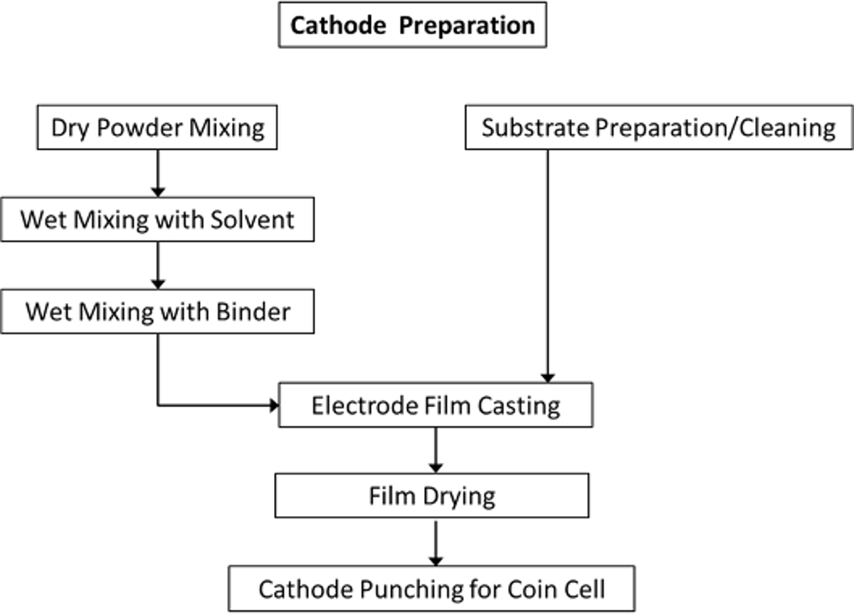
1. Cathode Preparation
Note: The schematic overview of the cathode fabrication process is presented in Figure 1.

Figure 1. Schematic overview of the steps utilized in the ETSL to create cathodes. The main process includes preparation and casting of the electrode slurry onto a cleaned aluminum substrate, followed by drying of the electrode sheet and incorporation into coin cells. Please click here to view a larger version of this figure.
- Aluminum Substrate Preparation
- Cut a 4.5" by 12" sheet of 15 µm thick aluminum (Al) foil using a paper cutter or scissors.
- Spray acetone on the surface of a clean plastic board to adhere the foil to the board and then place the foil sheet onto the board.
- Spray a generous amount of acetone on the surface of the foil and begin to scrub the entire surface using a scotch pad with small semi-circle motions. Spray additional acetone on the surface and wipe down residue with a paper towel.
- Repeat steps 1.1.2-1.1.3 for the opposite side and then repeat once more for the casting side.
- Wash etched Al sheet with deionized (DI) water on casting side first, then flip and repeat with opposite side. Re-scrub the surface of the Al foil as the DI water displays poor wettability and does not flow off the surface of the sheet without forming droplets. Repeat rinsing with isopropyl alcohol.
- Transfer the cleaned Al sheet between two paper towels and allow to dry for approximately 20 min under compression between two flat planes and paper towels.
- Slurry Preparation
- Choose the weights of active material, conductive additive and binder based on the desired composition of the electrode sheet. Choose a total dry powder weight of 1.25 g, with 70 wt% lithium-manganese-cobalt-oxide, LiNi1/3Mn1/3Co1/3O2 (NMC, active material), 20 wt% carbon black (conductive additive) and 10% Polyvinylidene Difluoride (PVDF, binder).
- Measure out 0.875 g of NMC and 0.25 g of carbon black and place into an agate mortar and pestle. Lightly mix the materials together without grinding. After a mixture starts to form, mill by hand in the mortar and pestle for 3-5 min, until a uniform powder is visually observed.
- Transfer the mixed powder into a disposable mixing tube with a piece of weigh paper. Add 16 glass balls (6 mm diameter) to the powder, along with 5.5 ml of 1-methyl-2-pyrrolidinone (NMP), the non-aqueous solvent.
- Place the disposable tube onto the tube drive station and lock into place. Turn the drive on and slowly increase to the maximum speed. Allow contents to mix for 15 min.
- Add 1.25 g of a 10% PVDF in NMP solution directly to the tube. Place the tube back onto the drive and allow mixing for 8 min, following the same procedure in 1.2.4. If the tube is allowed to sit for more than 5 min prior to casting (below), mix the contents for an additional 15 min.
- Casting and Drying
- Clean the metal surface of the automatic film applicator with isopropyl alcohol and a paper towel. Ensure that the doctor blade is clean, and is set to the desired casting height (200 µm).
- Apply a layer of isopropyl alcohol to the surface of the film applicator and place the dried aluminum substrate shiny-side down onto the surface. Press out the excess isopropyl alcohol with a folded paper towel until all wrinkles and isopropyl are removed. Take care to avoid tearing the substrate by firmly holding one of the substrate in place.
- Remove the mixing tube from the tube drive and open the container. Pour the slurry onto the surface of the substrate in a 2-3 inch line approximately 1 inch from the top (initial casting side) of the substrate. Remove any glass balls from the sheet with clean metallic tweezers.
- Set the casting speed to 20 mm/sec, and activate the casting arm of the film applicator.
- Lift the cast electrode from the surface of the film applicator using a thin piece of cardboard to ensure no wrinkles form on the sheet.
- Allow the electrode sheet to dry for 16 hr at RT (~24 °C) followed by drying at 70 °C for ~3 hr or until the sheet is dry. Ensure that the electrode is environmentally isolated in a fume hood or sealed chamber to prevent non-uniform drying.
- Cathode Electrode Punching
- Place the dried electrode sheet onto a cleaned sheet of aluminum metal. Take out a ½" hole punch and place it gently onto a region of the sheet with a uniform surface (edges may appear non-uniform). Slowly apply pressure to the punch (by hand) and "roll" the pressure around the edges of the punch to ensure a clean cut.
- (Alternative) Cut out an electrode disc utilizing a precise disc cutter in lieu of manual punching.
- Remove the electrode from the sheet with cleaned, plastic tweezers and place it into a labeled vial, with the electrode surface facing up. Repeat twice.
- (Optional) Place a punched electrode onto the surface of the lab press. Apply pressure of roughly 4 MPa (the optimal pressure will vary based on the press utilized). Repeat for the remaining electrodes.
- Place the vials in a vacuum oven and allow the electrodes to further dry at 120 °C at -0.1 MPa for 12 hr to remove any remaining moisture. After, remove the electrodes and weigh them within 0.0001 g.
- Open the antechamber of the glovebox and place the vials onto the tray. Close the chamber the door and ensure a tight seal by using two fingers to tighten antechamber hatch.
- Bring the vacuum down to -0.1 MPa, and then fill with Argon. Repeat this process 1-2 more times, depending on the samples transported into the glovebox.
2. Anode Sheet for Full Cell
- Repeat section 1 except using 9 µm thick copper foil as the substrate instead of aluminum foil. The composition of the sheet may be altered to fit specific needs.
3. Coin Cell Pre-assembly
Caution: The construction of coin cells is performed within an inert (Argon) environment within a glovebox. Extreme caution must be taken to minimize exposure of the internal environment to external atmosphere. Work with sharp materials within the glovebox should be minimized if possible. As a general rule, a task within the glovebox should take 3 times longer than the speed at which the task would be performed outside. Gloves should also be worn over the glovebox gloves to minimize exposure when working with different substances.
Note: The components needed for the construction of the coin cell, including the cap, case, wave springs, gaskets, spacers, lithium ribbon, electrolyte and remaining tools such as plastic tweezers (for component placement) are contained within an Argon-filled glovebox with O2 and H2O levels maintained below 0.5 parts per million. All components inserted into the glovebox (including lint-free task wipes) should be heated O/N in a vacuum oven at 120 °C at a pressure of -0.1 MPa to remove any moisture.
- Counter-electrode Preparation
- Within the glovebox, remove lithium ribbon (0.75 mm thick) from sealed container and roll out a portion onto the surface of a plastic block. Using a razor blade, carefully scrape away any black-colored oxidation from the foil surface. Take extreme caution to avoid cutting the gloves.
- Take a 9/16" hole punch and punch out a disk of the lithium ribbon. Use a finger (separated from the lithium by rubber gloves within glovebox) or other blunt tool to push the lithium disk out of the punch.
- Take a 0.5 mm thick spacer and gently apply the lithium disc to the surface between fingers. Ensure the lithium disc sticks to the center of the spacer and is flat — an uneven surface can cause uneven current distributions.
- Electrolyte Preparation
- Store the electrolyte of choice (in this case 1 M LiPF6 in EC/DEC 1:1 by vol) within the glovebox at all times in an aluminum container, as the electrolyte is photosensitive.
- Remove a small amount of electrolyte from the source container into a working container.
- Celgard Separator Preparation
- Place a sheet of the separator membrane between a folded sheet of printer paper. Place the folded paper and membrane onto a sheet of aluminum metal.
- Place a cushioning layer on top of the hole punch and use a hammer to punch out a ¾" diameter separator membrane.
- Transfer the punched separator discs into the glovebox utilizing the procedures outlined in 1.4.6-1.4.7.
Note: It is recommended to perform this step in bulk to avoid having to punch out individual separators for each coin cell being constructed.
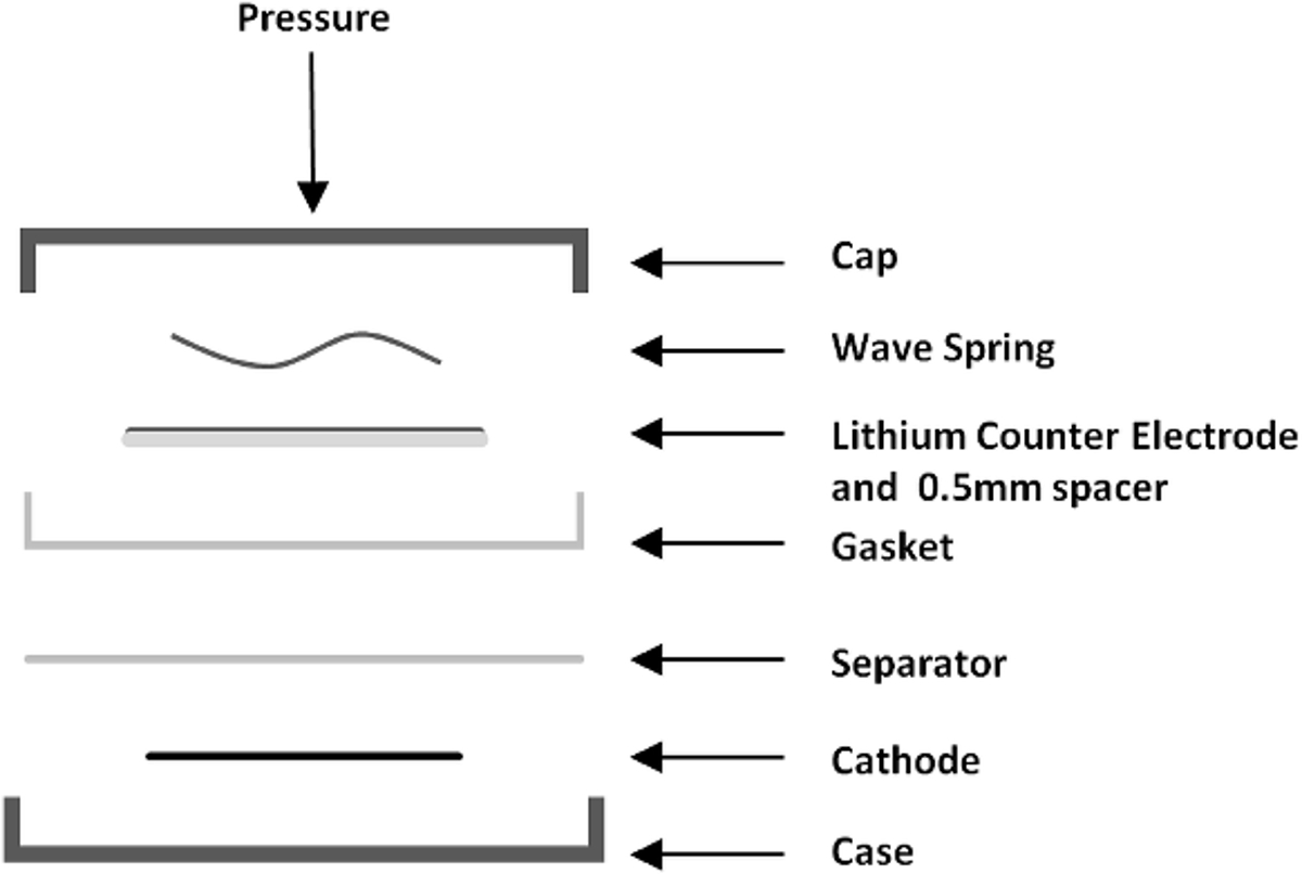
4. Coin Cell Assembly
Note: The configuration of the coin cell is presented in Figure 2.

Figure 2. Coin cell components displayed in order of placement within cell. Placement of the cathode is followed by the separator, gasket, counter electrode and wave spring, followed by sealing of the cell. Please click here to view a larger version of this figure.
- Open the interior antechamber door. Pull any components within the antechamber into the glovebox and reseal the interior antechamber door.
- Place a coin cell case into a small weigh boat. Place the cathode into the center of the coin cell case. Apply 1-2 ~30 µl drops of electrolyte to the center of the electrode and apply 1 drop on opposite sides of the rim of the case.
- Place a single ¾" separator onto the surface of the electrode. Force out any bubbles that become trapped using the flat edge of a pair of tweezers, and re-center the cathode by grabbing the case by the lip and lightly tapping the electrode into place. Apply an additional 1-2 drops of electrolyte to allow for better movement of the electrode if it sticks to its original position.
- Place the gasket into the case, with the flat side facing down and the lipped side facing up. Confirm the orientation of the gasket by holding up to the light prior to cell insertion.
- Apply 2-3 ~30 µl drops of electrolyte to the center of the cell, and place the prepared counter electrode onto the center with the lithium facing down. Place the wave spring on top of the centered counter electrode.
- Fill the cell to the brim (~0.7 ml) with electrolyte until it forms a curved, convex meniscus that covers most of the wave spring surface.
- Carefully place the coin cell cap on top of the cell utilizing the tweezers to hold the cap centered vertically over the cell. Take care to center the cap to avoid excessive loss of electrolyte.
- Press down on the cap (by hand) until it sets into the lip of the gasket. Transfer the cell to the crimper and ensure that the cell is centered in the groove of the crimping die. Crimp the cell to a pressure of ~ 6.2 MPa (900 psi) and release.
- Remove the cell from the crimper (by hand), and clean off any excess electrolyte. Repeat steps 4.2- 4.9 until all desired cells are constructed. Clean any spilled electrolyte, place trash into an appropriate container. Transfer the cells out of the glovebox and label them.
5. Electrochemical Evaluation
- Connect the cleaned cells to the battery cycler. Ensure the terminals are correctly connected by measuring the open circuit potential. If not positive, reverse the connections.
- Calculate the desired current based on the weight of the dried electrode on the surface of the aluminum substrate, the known mass of the aluminum, the active material percentage by weight, and the rated specific capacity of the active material utilized.
- With a measured electrode mass of 0.0090 g, aluminum disc mass of 0.0054 g, and rated capacity of 155 mAh/g, determine the desired current as (0.0090 g - 0.0054 g) × 0.70 × 155 mAh/g = 0.3906 mAh. For discharge at the current required to fully discharge the cell in 1 hr (1C), the applied current is 0.3906 mA.
- Set the schedule on the cycler to charge/discharge the cell between the upper and lower voltage levels of 4.2 V and 2.8 V. Cycle the cell 4 times at a rate of C/10 (galvanostatic, constant current). Then charge the cell once at C/10.
- After the 5th C/10 charge, remove the cell from the cycler (if necessary) and perform Electrochemical Impedance Spectroscopy19 (EIS) on the cell, after resting for 1 hr. Place the cell back on the cycler and discharge at C/10. Perform EIS once more after resting for 1 hr.
- Place the cell back onto the cycler and cycle the cell 5 times at rates of C/5, C, 2C, 5C, and 10C, followed by 100 1C cycles.
- Determine the specific capacity of the cells at each C-rate by dividing the capacity in mAh by the mass of active material present in the cathode. Calculate the capacity retention by dividing the average specific capacity of the last 5 1C cycles by the average specific capacity of the first 5 1C cycles.
Results
A properly cast electrode sheet should appear uniform in surface appearance and properly adhere to the current collector. Typically flaking of the electrode sheet is caused by either poor etching of the substrate, or having to little NMP in the initial mixing stage. Alternatively, too much NMP can cause the sheet to display a higher degree of porosity, which is not desirable. Lastly, a third pattern can be observed on the electrode surface, where pooling appears to occur. Interactions wit...
Discussion
The optimization of the wet mixing stages are crucial to the slurry viscosity and coating ability, which impacts the uniformity and adhesion of the electrode. Here a high-shear mixing method is utilized, where the solvent, additive, binder, and active material are mixed together utilizing the kinetic motions of the glass balls present in the vials. This mixing technique offers the benefit of much more rapid mixing times as compared to a magnetic stirrer method. Beyond this, this high shear mixing allows for more viscous ...
Disclosures
The authors have nothing to disclose.
Acknowledgements
This work is financially supported by Texas A&M University faculty research initiation grant (Mukherjee) and Texas State University start-up funding (Rhodes).
Materials
| Name | Company | Catalog Number | Comments |
| LiNiMNCoO2 (NMC, 1:1:1) | Targray | PLB-H1 | |
| CNERGY Super C-65 | Timcal | ||
| Polyvinylidene Difluoride (PVDF) | Kynar | Flex 2801 | |
| 1-Methyl-2-pyrrolidinone anhydrous, 99.5% NMP | Sigma-Aldrich | 328634 | |
| 1.0 M LiPF6 in EC/DEC (1:1 by vol) | BASF | 50316366 | |
| Celgard 2500 Separator | MTI | EQ-bsf-0025-60C | 25um thick; Polypropylene |
| Aluminum Foil | MTI | EQ-bcaf-15u-280 | |
| Lithium Ribbon | Sigma Aldrich | 320080 | 0.75 mm thickness |
| 2-Propanol, ACS reagent, ≥99.5% | Sigma Aldrich | 190764 | |
| Acetone, ACS reagent, ≥99.5% | Sigma Aldrich | 179124 | |
| Stainless Steel CR2032 Coin Cell Kit | Pred Materials | case, cap, and PP gasket | |
| Stainless Steel Spacer | Pred Materials | 15.5 mm diameter x 0.5 mm thickness | |
| Stainless Steel Wave Spring | Pred Materials | 15 mm diameter x 1.4 mm height | |
| Analytical Scale | Ohaus | Adventurer AX | |
| Agate Mortar and Pestle | VWR | 89037-492 | 5 inch diameter |
| Tube Drive | IKA | 3645000 | |
| 20 ml Stirring Tube | IKA | 3703000 | |
| Glass balls | McMaster-Carr | 8996K25 | 6 mm diameter |
| Automatic Film Applicator | Elcometer | K4340M10- | |
| Doctor Blade | Elcometer | K0003580M005 | |
| Die Set | Mayhew | 66000 | |
| Vacuum Oven | MTI | ||
| Vacuum Pump | MTI | ||
| Laboratory Press | MTI | YLJ-12 | |
| Hydraulic Crimper | MTI | MSK-110 | |
| Glovebox | MBraun | LABstar | |
| Battery Cycler | Arbin Instruments | BT2000 | |
| Potentiostat/Galvanostat/EIS | Biologic | VMP3 |
References
- Wagner, R., Preschitschek, N., Passerini, S., Leker, J., Winter, M. Current research trends and prospects among the various materials and designs used in lithium-based batteries. J Appl Electrochem. 43, 481-496 (2013).
- Whittingham, M. S. Lithium batteries and cathode materials. Chem Rev. 104, 4271-4301 (2004).
- Ellis, B. L., Lee, K. T., Nazar, L. F. Positive Electrode Materials for Li-Ion and Li-Batteries. Chem Mater. 22, 691-714 (2010).
- Tarascon, J. M., Armand, M. Issues and challenges facing rechargeable lithium batteries. Nature. 414, 359-367 (2001).
- Smith, K., Wang, C. Y. Power and thermal characterization of a lithium-ion battery pack for hybrid-electric vehicles. J Power Sources. 160, 662-673 (2006).
- Lu, L. G., Han, X. B., Li, J. Q., Hua, J. F., Ouyang, M. G. A review on the key issues for lithium-ion battery management in electric vehicles. J Power Sources. 226, 272-288 (2013).
- Dunn, B., Kamath, H., Tarascon, J. M. Electrical Energy Storage for the Grid: A Battery of Choices. Science. 334, 928-935 (2011).
- Cich, E. R. Button Cell battery. US patent. , (1972).
- Elul, S., Cohen, Y., Aurbach, D. The influence of geometry in 2D simulation on the charge/discharge processes in Li-ion batteries. J Electroanal Chem. 682, 53-65 (2012).
- Buqa, H., Goers, D., Holzapfel, M., Spahr, M. E., Novak, P. High rate capability of graphite negative electrodes for lithium-ion batteries. J Electrochem Soc. 152, A474-A481 (2005).
- Chen, Y. H., Wang, C. W., Zhang, X., Sastry, A. M. Porous cathode optimization for lithium cells: Ionic and electronic conductivity, capacity, and selection of materials. J Power Sources. 195, 2851-2862 (2010).
- Arora, P., Doyle, M., Gozdz, A. S., White, R. E., Newman, J. Comparison between computer simulations and experimental data for high-rate discharges of plastic lithium-ion batteries. J Power Sources. 88, 219-231 (2000).
- Dillon, S. J., Sun, K. Microstructural design considerations for Li-ion battery systems. Curr Opin Solid St M. 16, 153-162 (2012).
- Harris, S. J., Lu, P. Effects of Inhomogeneities-Nanoscale to Mesoscale-on the Durability of Li-Ion Batteries. J Phys Chem C. 117, 6481-6492 (2013).
- Liu, G., Zheng, H., Song, X., Battaglia, V. S. Particles and Polymer Binder Interaction: A Controlling Factor in Lithium-Ion Electrode Performance. J Electrochem Soc. 159, A214-A221 (2012).
- Zheng, H. H., Yang, R. Z., Liu, G., Song, X. Y., Battaglia, V. S. Cooperation between Active Material, Polymeric Binder and Conductive Carbon Additive in Lithium Ion Battery Cathode. J Phys Chem C. 116, 4875-4882 (2012).
- Liu, Z. X., Battaglia, V., Mukherjee, P. P. Mesoscale Elucidation of the Influence of Mixing Sequence in Electrode Processing. Langmuir. 30, 15102-15113 (2014).
- Liu, Z. X., Mukherjee, P. P. Microstructure Evolution in Lithium-Ion Battery Electrode Processing. J Electrochem Soc. 161, E3248-E3258 (2014).
- Zheng, H. H., Tan, L., Liu, G., Song, X. Y., Battaglia, V. S. Calendering effects on the physical and electrochemical properties of Li[Ni1/3Mn1/3Co1/3]O-2 cathode. J Power Sources. 208, 52-57 (2012).
- Zheng, H. H., Li, J., Song, X. Y., Liu, G., Battaglia, V. S. A comprehensive understanding of electrode thickness effects on the electrochemical performances of Li-ion battery cathodes. Electrochim Acta. 71, 258-265 (2012).
- Marks, T., Trussler, S., Smith, A. J., Xiong, D. J., Dahn, J. R. A Guide to Li-Ion Coin-Cell Electrode Making for Academic Researchers. J Electrochem Soc. 158, A51-A58 (2011).
- Li, C. C., Wang, Y. W. Binder Distributions in Water-Based and Organic-Based LiCoO2 Electrode Sheets and Their Effects on Cell Performance. J Electrochem Soc. 158, A1361-A1370 (2011).
Reprints and Permissions
Request permission to reuse the text or figures of this JoVE article
Request PermissionThis article has been published
Video Coming Soon
Copyright © 2025 MyJoVE Corporation. All rights reserved