A subscription to JoVE is required to view this content. Sign in or start your free trial.
Method Article
Operation of a 25 KWth Calcium Looping Pilot-plant with High Oxygen Concentrations in the Calciner
In This Article
Summary
This manuscript describes a procedure for operating a calcium looping pilot-plant for post-combustion carbon capture with high oxygen concentrations in the calciner in order to reduce or eliminate the flue gas recycle.
Abstract
Calcium looping (CaL) is a post-combustion CO2 capture technology that is suitable for retrofitting existing power plants. The CaL process uses limestone as a cheap and readily available CO2 sorbent. While the technology has been widely studied, there are a few available options that could be applied to make it more economically viable. One of these is to increase the oxygen concentration in the calciner to reduce or eliminate the amount of recycled gas (CO2, H2O and impurities); therefore, decreasing or removing the energy necessary to heat the recycled gas stream. Moreover, there is a resulting increase in the energy input due to the change in the combustion intensity; this energy is used to enable the endothermic calcination reaction to occur in the absence of recycled flue gases. This paper presents the operation and first results of a CaL pilot plant with 100% oxygen combustion of natural gas in the calciner. The gas coming into the carbonator was a simulated flue gas from a coal-fired power plant or cement industry. Several limestone particle size distributions are also tested to further explore the effect of this parameter on the overall performance of this operating mode. The configuration of the reactor system, the operating procedures, and the results are described in detail in this paper. The reactor showed good hydrodynamic stability and stable CO2 capture, with capture efficiencies of up to 70% with a gas mixture simulating the flue gas of a coal-fired power plant.
Introduction
CO2 emissions and the resulting global warming are critical environmental issues that have attracted a large amount of research in the past years. Carbon capture and storage (CCS) has been acknowledged as a potential technology for reducing CO2 emissions to the atmosphere1,2. The most challenging part of the CCS chain is the capture of CO2, which is also the most costly stage3. In consequence, there has been a focus on developing new technologies for CO2 capture from power plants and other industrial facilities.
CaL as a post-combustion CO2 capture technology, was first proposed by Shimizu et al.4 CO2 is captured by a CaO-based sorbent at 600-700 °C in a reactor called a carbonator, and released by subsequent calcination at 850-950 °C (in a calciner) according to Eq. (1), to produce a high-purity CO2 stream suitable for sequestration5,6. The CaL cycle utilises fluidized beds, which represent an optimal configuration for this process, since they allow for large amounts of solids to be circulated easily from one reactor to the other4,5,6,7,8.
CaO (s) + CO2 (g) ⇔ CaCO3 (s) ΔH25 °C = -178.2 kJ/mol (1)
This concept has been demonstrated at pilot scale by various groups and with different configurations and scales, such as the 0.2 MWth pilot in Stuttgart, the 1 MWth pilot in Darmstadt, the 1.7 MWth pilot in La Pereda and the 1.9 MWth unit in Taiwan9,10,11,12,13,14,15,16. Although this process has been proven, there are still possibilities for increasing its thermal efficiency, such as by modifying the standard operating conditions and changes in the design of the reactor configuration.
The use of heat pipes between the combustor and calciner has been studied instead of oxy-combusting fuel in the calciner. The results for the CO2 capture performance are comparable with those of a conventional CaL pilot-plant, however, this process has higher plant efficiencies and lower CO2 avoidance costs17. Martínez et al.18 investigated the heat integration possibilities in order to preheat the solid material entering the calciner and to reduce the heat needed in the calciner. The results showed 9% reduction in the coal consumption when compared with that of the standard case. Other studied possibilities for heat integration have also considered internal and external integration options19.
One of the main problems of the CaL cycle from the economic point of view is to supply the energy needed in the calciner by means of fuel combustion20. Increasing the oxygen concentration in the calciner's inlet is proposed in order to reduce or even avoid the need of CO2 recycle to the calciner. This alternative reduces the capital costs (reduced size of calciner and air separation units (ASU)), which can significantly improve the competitiveness of this process. The drastic change in the combustion conditions can be attained by exploiting the endothermic calcination reaction and the large CaO/CaCO3 flow circulating from the carbonator operating at lower temperatures (neither advantage is available with the oxy-combustion technology).
This work aims to develop a standard operating procedure for running a CaL pilot plant with a Circulating Fluidized Bed (CFB) carbonator and a Bubbling Fluidized Bed (BFB) calciner with 100% O2 concentration in the calciner's inlet. Several experimental campaigns have been run during the commissioning of the pilot plant to ensure proper operation as the oxygen concentration increased. Also, three limestone particle size distributions (100-200 µm; 200-300 µm; 300-400 µm) were studied to investigate how this parameter affects the elutriation of particles and capture efficiency in this operating mode.
Protocol
1. Material Preparation
- Sieve the limestone (~50 kg of raw material) to the desired particle size distribution (300-400 µm or another distribution depending on the experiment) using a mechanical shaker. Put the sieved material in pots next to the calciner for feeding during the test.
- Prepare the material in batches to be introduced into the reactor. The batches are generally 0.5 L or 1 L (1 L of limestone is roughly 1.5 kg), but this can vary depending on the operating parameters.
2. Start-up Procedure
CAUTION: Extremely high temperatures are achieved here. Suitable PPE such as gloves, eye glasses, laboratory coat and safety shoes are required.
- Heat-up of Reactors
- Start the low flow of N2 in the carbonator (60 L/min) and calciner (20 L/min) as well as the loop-seals (10 L/min) in the rotameters.
- Turn on the carbonator transformers manually. Set the temperature of all electrical preheaters of the carbonator at 600 °C.
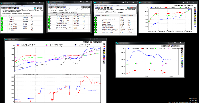
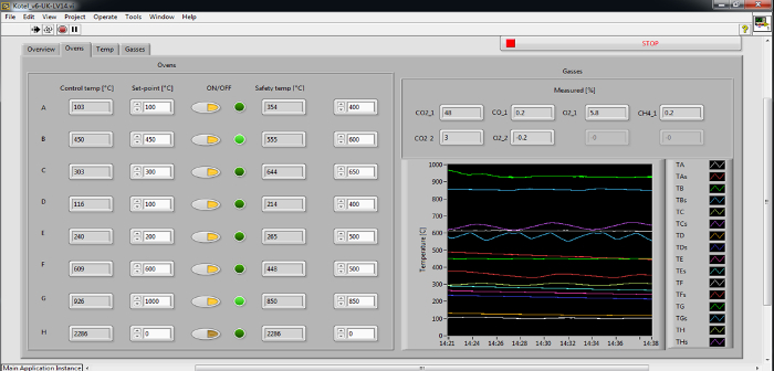
- Start acquiring data (for gas temperatures and pressures, use the recording button in the software). The data include temperatures, pressures and gas composition of both reactors. In Figure 1 and Figure 2, screenshots of the data acquisition system are shown.
- Turn on the calciner gas preheaters. Turn on the heater around the calciner to 600 °C measured inside the BFB via a thermocouple.
NOTE: Data such as temperature, pressure and gas composition are already being acquired as stated in step 2.1.3. - Put 3 L of the sieved limestone into the BFB in the calciner. First open the top valve, introduce the material in the down-pipe and close the top valve, then open the bottom valve so that the material flows into the reactor.
- Heat the material in the BFB to above 650 °C (by the electrical heater around the calciner).
NOTE: This usually takes ~1 h, during this time check the data acquisition and the pressures in the fluidized beds.

Figure 1: Screenshot of temperature and pressure data acquisition for both reactors. Please click here to view a larger version of this figure.

Figure 2: Screenshot of temperature data acquisition for the preheating system. Please click here to view a larger version of this figure.

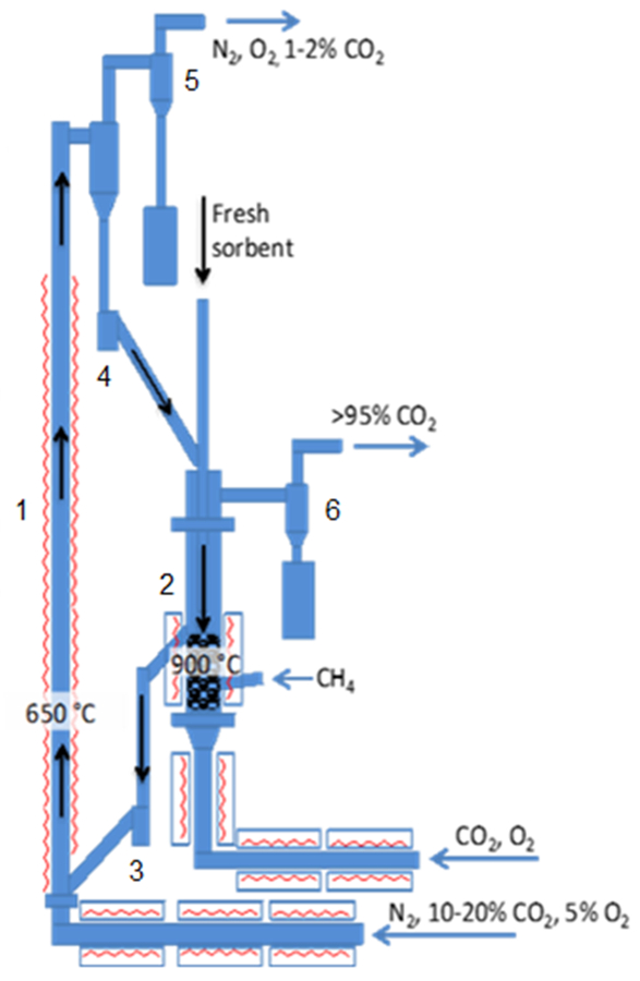
Figure 3: Schematic of the 25 kWth CaL (CFB carbonator and BFB calciner). 1: carbonator; 2: calciner; 3: lower loop-seal; 4: upper loop-seal; 5: carbonator cyclone; 6: calciner cyclone. Please click here to view a larger version of this figure.
- Start combustion in calciner
- Increase the oxygen concentration in the calciner from 0 to 40% vol, making sure that the concentration is stable before starting the combustion.
- Start the stoichiometric flow of natural gas manually using a rotameter making sure that the combustion is stable.
NOTE: The natural gas flow should be increased carefully. Check that the data show an appropriate level of combustion reaction. - Increase the oxygen concentration in the calciner in 20% vol increments by adjusting the natural gas flow rotameter to ensure stoichiometric combustion.
NOTE: This process should be performed with extreme care. If any suspicion arises that the combustion is not occurring as expected from the preliminary calculations then stop the flow of natural gas and switch the oxygen flow to nitrogen for safe operation. Identify the source of this discrepancy. The overall duration of this process is about 1 h. - Achieve 100% oxygen concentration natural gas combustion.
NOTE: The temperature and gas composition data should be carefully followed throughout all the testing, but especially when the combustion is taking place in 100% oxygen. - Add limestone in 0.5 L increments until there is 7 L in the fluidized bed. Calcine all the material in the fluidized bed of the calciner (the estimated calcination temperature is 800-850 °C for the batch present in the calciner and the calciner temperature for the following batches).
- Increase the flow of N2 in the carbonator to start the circulation. Check the circulation view port regularly to ensure proper circulation.
- Calcine all the available limestone circulating in the rig before starting the CO2 capture.
3. Stable Operation
- Manually switch the carbonation gas from N2 to 15% vol CO2 using the rotameter, which allows the calcined limestone to begin capturing CO2.
- Adjust the flows in the calciner manually using the rotameters to achieve a stable 930-950 °C temperature in the calciner by regulating the flow of natural gas (NG) and oxygen (within the optimal fluidization regime). The O2 flow is usually 100% with enough bed material, but it is adjusted throughout the experiment.
- When the material starts to decline in activity (above 5% CO2 concentration at the exit of the carbonator, which is acquired continuously by the software as described in step 2.1.3), add more limestone.
4. Shut-down Procedure
- Manually turn off the natural gas flow using the rotameter and decrease the oxygen flow, and switch the gases in both reactors to N2. Turn off all the heaters (calciner and carbonator).
- Allow the temperature of the inventory of the rig to decrease (normally overnight), and empty the reactors when they are at room temperature.
- Weigh the extracted solids and perform a standard sieve analysis. Characterize the material: porosimetry, composition (X-ray fluorescence spectrometry, XRF)21,22 and microscopic structure (scanning electron microscopy, SEM).
Results
The experimental set-up is shown in Figure 3. The plant comprises two interconnected fluidized-beds. Namely, the carbonator is a CFB with 4.3 m height and 0.1 m internal diameter (ID); while the calciner is a BFB with 1.2 m height and 0.165 m ID. The solid transport from one reactor to the other is controlled by two loop-seals fluidized with nitrogen. Both reactors are fed a mixture of gas through a preheating line, and both are electrically heated; moreover,...
Discussion
The operation of the calciner with an inlet of 100% vol oxygen is achievable, based on exploiting the endothermic nature of the calcination reaction, as well as the fact that the solids circulate between the two reactors at different temperatures. This operating mode aims to make the CaL process more economically promising by reducing capital and operating costs. As the recycle of flue gas (mainly CO2, water vapor and unreacted O2) is reduced or even eliminated, the heat consumed to preheat this str...
Disclosures
The authors have nothing to disclose.
Acknowledgements
The research leading to these results has received funding from the European Community's Research Fund for Coal and Steel (RFCS) under grant agreement n° RFCR-CT-2014-00007. This work was funded by the UK Carbon Capture and Storage Research Centre (UKCCSRC) as part of Call 2 projects. UKCCSRC is supported by the Engineering and Physical Sciences Research Council (EPSRC) as part of the Research Council's UK Energy Programme, with additional funding from the Department of Business, Energy and Industrial Strategy (BEIS - formerly DECC). The authors would also like to thank Mr. Martin Roskilly for his enormous help throughout the course of this work.
Materials
| Name | Company | Catalog Number | Comments |
| Longcal limestone | Loncliffe | Longcal SP52 | n/a |
| Mechanical Shaker | SWECO | LS24S544+C | Mechanical siever to separate particles |
| Oxygen | BOC | n/a | BOC cylinders |
| Nitrogen | BOC | n/a | BOC tank |
| Carbon dioxide | BOC | n/a | BOC tank |
| Natural gas | n/a | n/a | Taken from the line |
References
- Bernstein, L., Lee, A., Crookshank, S. Carbon dioxide capture and storage: a status report. Climate Policy. 6 (2), 241-246 (2011).
- Boot-Handford, M. E., et al. Carbon capture and storage update. Energy Environmental Science. 7 (1), 130-189 (2014).
- Herzog, H. J. Scaling up carbon dioxide capture and storage: from megatons to gigatons. Energy Economics. 33 (4), 597-604 (2011).
- Shimizu, T., Hirama, T., Hosoda, H., Kitano, K., Inagaki, M., Tejima, K. A twin fluid-bed reactor for removal of CO2 from combustion processes. Chemical Engineering Research and Design. 77 (1), 62-68 (1999).
- Blamey, J., Anthony, E. J., Wang, J., Fennell, P. S. The calcium looping cycle for large-scale CO2 capture. Progress in Energy and Combustion Science. 36 (2), 260-279 (2010).
- Masnadi, M. S., Grace, J. R., Bi, X. T., Ellis, N., Lim, C. J., Butler, J. W. Biomass/coal steam co-gasification integrated with in-situ CO2 capture. Energy. 83, 326-336 (2015).
- Abanades, J. C., Anthony, E. J., Lu, D. Y., Salvador, C., Alvarez, D. Capture of CO2 from combustion gases in a fluidized bed of CaO. AIChE Journal. 50 (7), 1614-1622 (2004).
- Hughes, R. W., Lu, D. Y., Anthony, E. J., Macchi, A. Design, process simulation and construction of an atmospheric dual fluidized bed combustion system for in situ CO2 capture using high-temperature sorbents. Fuel Processing Technology. 86 (14), 1523-1531 (2005).
- Lu, D. Y., Hughes, R. W., Anthony, E. J. Ca-based sorbent looping combustion for CO2 capture in pilot-scale dual fluidized beds. Fuel Processing Technology. 89 (12), 1386-1395 (2008).
- Hawthorne, C., et al. CO2 capture with CaO in a 200 kWth dual fluidized bed pilot plant. Energy Procedia. 4, 441-448 (2011).
- Sánchez-Biezma, A., et al. Postcombustion CO2 capture with CaO. Status of the technology and next steps towards large scale demonstration. Energy Procedia. 4, 852-859 (2011).
- Dieter, H., Hawthorne, C., Zieba, M., Scheffknecht, G. Progress in calcium looping post combustion CO2 capture: successful pilot scale demonstration. Energy Procedia. 37, 48-56 (2013).
- Arias, B., et al. Demonstration of steady state CO2 capture in a 1.7 MWth calcium looping pilot. International Journal of Greenhouse Gas Control. 18, 237-245 (2013).
- Ströhle, J., Junk, M., Kremer, J., Galloy, A., Epple, B. Carbonate looping experiments in a 1MWth pilot plant and model validation. Fuel. 127, 13-22 (2014).
- Bidwe, A. R., Hawthorne, C., Dieter, H., Dominguez, M. A., Zieba, M., Scheffknecht, G. Cold model hydrodynamic studies of a 200kWth dual fluidized bed pilot plant of calcium looping process for CO2 Capture. Powder Technology. 253, 116-128 (2014).
- Chang, M. H., et al. Design and experimental testing of a 1.9 MWth calcium looping pilot plant. Energy Procedia. 63, 2100-2108 (2014).
- Reitz, M., Junk, M., Ströhle, J., Epple, B. Design and operation of a 300kWth indirectly heated carbonate looping pilot plant. International Journal of Greenhouse Gas Control. 54, 272-281 (2016).
- Martínez, A., Lara, Y., Lisbona, P., Romeo, L. M. Energy penalty reduction in the calcium looping cycle. International Journal of Greenhouse Gas Control. 7, 74-81 (2012).
- Perejón, A., Romeo, L. M., Lara, Y., Lisbona, P., Martínez, A., Valverde, J. M. The calcium-looping technology for CO2 capture: on the important roles of energy integration and sorbent behavior. Appl Energy. 162, 787-807 (2016).
- Mantripragada, H. C., Rubin, E. S. Calcium looping cycle for CO2 capture: Performance, cost and feasibility analysis. Energy Procedia. 63, 2199-2206 (2014).
- . . ASTM C1271-99(2012), Standard Test Method for X-ray Spectrometric Analysis of Lime and Limestone. (2012), C1271-C1299 (2012).
- . . ASTM C25-11e2, Standard Test Methods for Chemical Analysis of Limestone, Quicklime, and Hydrated Lime. , C25-C11 (2011).
- Alonso, M., Rodríguez, N., Grasa, G., Abanades, J. C. Modelling of a fluidized bed carbonator reactor to capture CO2 from a combustion flue gas. Chem Eng Sci. 64 (5), 883-891 (2009).
- Manovic, V., Anthony, E. J. Parametric study on the CO2 capture capacity of CaO-based sorbents in looping cycles. Energy Fuels. 22 (3), 1851-1857 (2008).
- Duhoux, B., Mehrani, P., Lu, D. Y., Symonds, R. T., Anthony, E. J., Macchi, A. Combined Calcium Looping and Chemical Looping Combustion for Post-Combustion Carbon Dioxide Capture: Process Simulation and Sensitivity Analysis. Energy Technol. 4 (10), 1158-1170 (2016).
- Erans, M., Manovic, V., Anthony, E. J. Calcium looping sorbents for CO2 capture. Appl Energy. 180, 722-742 (2016).
- Basu, P. A study of agglomeration of coal-ash in fluidized beds. The Canadian Journal of Chemical Engineering. 60 (6), 791-795 (1982).
Reprints and Permissions
Request permission to reuse the text or figures of this JoVE article
Request PermissionThis article has been published
Video Coming Soon
Copyright © 2025 MyJoVE Corporation. All rights reserved