Method Article
組織学でMRIをマージするために、3D印刷技術を活用:脳セクショニングのためのプロトコルを
要約
このプロトコルの全体的な目標は、正確にカスタマイズされた3Dプリント脳ホルダーとスライサーボックスの作成によって組織学切片で磁気共鳴画像(MRI)画像ボリュームを揃えることです。
要約
Magnetic resonance imaging (MRI) allows for the delineation between normal and abnormal tissue on a macroscopic scale, sampling an entire tissue volume three-dimensionally. While MRI is an extremely sensitive tool for detecting tissue abnormalities, association of signal changes with an underlying pathological process is usually not straightforward. In the central nervous system, for example, inflammation, demyelination, axonal damage, gliosis, and neuronal death may all induce similar findings on MRI. As such, interpretation of MRI scans depends on the context, and radiological-histopathological correlation is therefore of the utmost importance. Unfortunately, traditional pathological sectioning of brain tissue is often imprecise and inconsistent, thus complicating the comparison between histology sections and MRI. This article presents novel methodology for accurately sectioning primate brain tissues and thus allowing precise matching between histology and MRI. The detailed protocol described in this article will assist investigators in applying this method, which relies on the creation of 3D printed brain slicers. Slightly modified, it can be easily implemented for brains of other species, including humans.
概要
In vivo MRI provides a noninvasive and sensitive measure of tissue integrity at the macroscopic level. Changes in MRI signal intensity seen in vivo are outcome measures in many ongoing clinical trials.1 While the intensity changes seen via MRI can identify areas of abnormality in the context of the whole brain, they are often not sufficiently specific to differentiate pathological processes. This is especially true of dynamic processes involving multiple pathologies. For example, in multiple sclerosis (MS) or its animal model, experimental autoimmune encephalomyelitis (EAE), inflammation, edema, myelin degradation, axonal destruction, gliosis, and neuronal death overlap. 2, 3 To obtain the necessary specificity regarding the underlying pathology, context must be taken into account, together with knowledge of the histology of the MRI-identified abnormal tissues.
However, even in well-controlled animal experiments, matching histology with in vivo MRI is fundamentally challenging for various reasons. First, the difference in dimensional scales between histology sections and MRI is of several orders of magnitude.4 Second, for proper comparison, the orientation of MRI slice plane must match the sectioning plane of the brain tissue when cut. Due to the shape of the brain, it is very difficult to make consistently straight and accurate cuts when the brain is sitting on a flat surface. Third, the large size of the brain relative to a potentially small area of interest (lesion, tumor, etc.) creates a "needle-in-a-haystack" scenario for the pathologist processing the tissue. Fourth, even when the target tissue is found, it is commonly processed in such a way as to render virtually impossible an association with the original MRI data. Finally, traditional pathological sectioning of brain tissue is often imprecise and inconsistent, further complicating the comparison between histology sections and MRI images.
Previous attempts to overcome these challenges relied on the use of deformational algorithms to coregister the data and/or placement of fiducial markers within or around the tissue as a reference.5, 6, 7, 8 The former approach requires complex computational models that are particularly susceptible to complications due to data formatting, imaging artifacts, and changes caused by tissue processing.4 On the other hand, the latter approach introduces the possibility of contaminating or otherwise harming the tissue itself.9
The approach described here improves the transition between modalities through the use of postmortem MRI to bridge the gap between in vivo MRI and histology. Postmortem MRI provides three-dimensional (3D) images of the brain at higher resolution than can be achieved in vivo and furthermore provides the data needed for producing a morphologically accurate model of the brain surface. This digital model can then be used to create a 3D-printed custom holder for the brain. With careful positioning, the brain holder allows for precise, MRI-oriented brain sectioning, reducing the need for complex mathematical algorithms, and enables a focus on specific regions for targeted sampling.
Our laboratory recently introduced new methods for creating custom brain holders and slicers using postmortem MRI and 3D-printing technology for human10 and marmoset brains.4 The two methods allow for a more accurate correlation between MRI and histology in a research setting, and ultimately allow a deeper understanding of the specific pathology underlying MRI abnormalities. Carefully designed experiments, in which the brain is sampled repeatedly over time in vivo, can provide context for interpretation of the pathology, which in turn can add specificity to interpretation of the MRI. Here, we present a modified protocol in a unified framework that can be applied to any brain tissue, whether it derive from nonhuman primates, rodents, or humans. We provide detailed instructions, and a corresponding video, for the marmoset sectioning. Although the overall protocol applies to any type of brain, due to differences in MRI acquisition and tissue size, as well as the challenges encountered when dealing with specific brain types, there are some differences in the approach depending on the type of brain being processed. In this presentation, sections with "human" will denote differences in protocol specific to the human brain.
プロトコル
全ての動物取り扱いおよび本明細書に記載の手順は、神経疾患の国立研究所と脳卒中動物実験委員会によって承認されたプロトコルに従って実施しました。脳は、EAEを発症するように誘導され、共通のマーモセット( マーモセット属コモンマーモセット )から収集しました。 11脳を3週間、4%パラホルムアルデヒドtranscardial灌流による安楽死の後一年の間に10%ホルマリン中で保存しました。
1.死後MRIの準備と取得
- マーモセットの脳
- フッ素系オイル、パラフィン、およびマーモセットの脳の綿ガーゼ、50ミリリットルの遠心分離管、小さなへら、〜30mlでワークステーションを準備します。
- 20ミリリットルマークにフッ素系オイルやガーゼでチューブを埋めます。道に沿って気泡を除去するためにガーゼを圧縮します。
- ペーパータオルで脳の表面から乾いホルマリン。の底部に向かって前頭極で脳を挿入テレビ。慎重にその位置を固定する側面の周りより多くのガーゼを使用してチューブに脳を固定します。追加のMRIスキャンの設定のためのMRI脳クレードルを作成する方法のための補助的なセクション11を参照してください。
- ガーゼやフッ素系オイルとチューブの残りの部分を埋めます。慎重に道に沿って気泡を除去。キャップを固定し、パラフィンでチューブを密封します。
- 大脳縦裂に沿ってキャップをマークします。ペーパータオルでチューブをラップし、マーク上部中央とコイルに挿入します。
- 2DスピンエコーT2を取得します。パラメータを表1に示します。
- Mipavで10解剖学的150ミクロンT2-weigted買収を開き、6 回目の買収に登録します。
注:登録はパウエルの呼び出しブレントの検索アルゴリズムで、自由、窓付きのsinc補間、正規化相互相関コスト関数の9度と最適化された自動登録の3.5Dアルゴリズムです。回転は10からサンプリングしました6; 1°をインクリメント5度をインクリメント粗い回転と細かい回転に-10°です。次に、登録画像を平均化:ユーティリティ、イメージの電卓バルク画像、平均。
- 人間の脳
- 中脳のレベルでのカットを使用して、脳幹から前脳を分離します。 10半球はまた、正中線ダウンカットで分離することができます。
- 一方の端部に半球ドーム、他端に注ぎ口を有する円筒形の管で前脳を置きます。
- 注ぎ口を介してフッ素系オイルでチューブを埋めます。注ぎ口を通して〜30分の穏やかな吸引を使用して気泡を除去。
- 3D T1-MPRAGEを取得します。パラメータを表1に示します。
2.解凍脳表面:Mipav 7.2
- 冠状向きでMRIを開きます。
- アルゴリズム、変換ツール、変換、再サンプルを選択します。ユーザー定義サイズを選択して、ISOTにリサンプリングropicボクセル:0.1×0.1×0.1ミリメートル。 Brain_MRI_ResampledとしてリサンプリングMRIを保存します。人間:等方性ボクセル0.3×0.3×0.3ミリメートルにリサンプリング。
- アルゴリズム、フィルタ(空間)、非線形ノイズリダクション]を選択します。デフォルトの設定を使用して、[OK]をクリックします。
- 表示ルックアップテーブルを選択し、二重しきい値]ボタンをクリックします。脳全体をカバーするために、グラフ上のスライダーをドラッグします。
- 最小/最大を使用してアルゴリズム、セグメンテーション、しきい値、しきい値を選択します。 「下限」ボックスに(ちょうどスケールの下)強度グラフの左下隅にある値を入力します。出力画像タイプのために「バイナリ」を選択し、チェックを外し、「反転しきい値を。」
- アルゴリズム、形態素を選択して、穴を埋めます。 「2.5Dでのプロセス」をチェック
- これは完全な脳のMRIであるため、満たされる必要がある後脳および皮質の間にいくつかの空のスペースがあります。人間の脳:このステップをスキップします。
- ラインVOIを使用して、接続に描きます最も外側にある点で、脳の両側の後脳および皮質の間。脳を介してこれを続けます。
- VOI、VOI変換、バイナリマスクにすべてを選択します。ユーティリティを選択し、画像の電卓。選択OR演算子]ドロップダウンメニューから、脳のマスクを選択します。 「デスティネーションイメージの種類を推進する」を選択
- アルゴリズム、形態素を選択して、穴を埋めます。チェック "2.5Dでのプロセス」
- Brain_Model.niiなどのバイナリマスクを保存します。
- アルゴリズム、抽出表面(マーチングキューブ)を選択します。マスク画像を選択し、Brain_Model.plyとして保存します。
3.スライス選択場所:Mipav 7.2
- 興味や開始位置の組織を識別します。意図されたスラブの厚さを計算します。マーモセットの脳では、セクションごとに30 MRIスライス、およびブレードギャップあたり5 MRIスライスを、カウントが〜3.5ミリメートルのスラブで、その結果、0.5ミリメートルブレードギャップが3mmのセクションを作成します。人間の脳:セクションあたり20 MRIのスライス、および4のMRI SLブレードギャップあたりの氷は、〜7.2ミリメートルのスラブで、その結果、1.2ミリメートルブレードギャップを有する6ミリメートルのセクションを作成します。
- 第1ブレードギャップの位置では、「ボックスVOI」をクリックし、脳の上にボックスを描画します。それを選択するために、ボックスの内側をクリックします。コピーとブレードギャップに対応する各MRIスライスの輪郭を貼り付けます。
- 切片厚に対応するMRIスライスの数によって前方にスキップして次のブレードギャップに対応する輪郭をコピーして貼り付けます。脳を介してこのプロセスを繰り返します。
- VOI、VOIの変換、バイナリマスクにすべてを選択します。 Blade_Gaps.niiとして保存します。
- アルゴリズム、抽出表面(マーチングキューブ)、マスク画像、Blade_Gaps.plyを選択します 。
4. MRIブレードマップの作成:Mipav 7.2
- Brain_MRI_ResampledとBlade_Gaps.nii画像を開きます。
- Blade_Gaps.niiイメージが選択すると、ユーティリティを選択し、画像の数学。画像タイプと乗算を推進選択します。値として万を入力します。
- ユーティリティを選択し、画像の電卓。 [追加]を選択して、[画像]ドロップダウンボックスからBrain_MRI_Resampledイメージを選択します。先の画像の種類を推進選択します。
- Brain_BladeMap.niiとしてこのイメージを保存します。
- Triplanarビューをクリックすることで、脳がスライスされた場所は、三つの直交ビューで見ることができます。
5.脳とブレードギャップサーフェスをインポート:Netfabbプロフェッショナル
- パートを選択し、部品を追加します。ファイルBrain_Model.plyとBlade_Gaps.plyを選択します。
- 脳を選択し、修復モードをクリックしてください。修復モードでは:
- シェルの選択]ボタンをクリックし、脳をクリックしてください。
- 他のメッシュを選択するためのトグル選択ボタンをクリックします。他のメッシュを削除するには、Removeをクリックします。
- 適用修復をクリックし、古い部分を削除します。
- 右脳をクリックしてください。移動を選択します。クリックします。原点ボタンに。表示されるXYZパラメータを記録します。これらの翻訳パラメータはMipavで設定ブレードの位置を維持するために必要とされます。翻訳をクリックします。その後、ウィンドウを閉じます。 (複数回を変換]をクリックしないでください。それは、再び同じパラメータを使用して変換します。)
- Blade_Gapsモデルを選択します。右の部分をクリックし、移動を選択します。 XYZパラメータボックスに、以前に記録されたXYZ値を入力します。今すぐ翻訳をクリックしてウィンドウを閉じます。
- Brain_Modelモデルを選択し、修復モードをクリックしてください。修復モードでは:
- シェルの選択]ボタンをクリックし、脳をクリックしてください。
- 右クリックして、スムーズな三角形を選択します。 4-5回の反復を入力します。防止のボリューム縮小を確認してください。人間の脳:1-2の繰り返し。
- 右クリックして、三角形を減らして選択します。ターゲット三角形カウントで200000を入力して、[実行]をクリックします。
- 自動修復、デフォルトの修理をクリックします。そして、適用の修復をクリックします
- 右クリックし、名前を変更します。 Smoothed_Brain_Modelとして平滑化された脳の名前を変更します。
- Smoothed_Brain_Modelを選択します 。右クリックし、エクスポート、STL。
6.編集脳等高線:Meshmixer
- MeshmixerにSmoothed_Brain_Modelをインポートします。
- メッシュへの調整を行うために彫刻し、選択ツールを使用してください。編集が含まれます:
- 堅牢な滑らかなスカルプトツールを使用してください。ラインのVOIに対応する領域を滑らか。人間の脳:このステップをスキップします。
- ボックスに伏せされる皮質の表面を滑らかに。
- メッシングや編集プロセスで作成されている可能性があり、小さなくぼみを離れて滑らか。
- 分析、インスペクタ、Autorepairすべてを選択します。
- Smoothed_Edited_Brain_ModelとしてSmoothed_Brain_Modelをエクスポートします 。
7.脳スライサーボックスの作成:Netfabbプロフェッショナル
- パートを選択し、パートを追加します。フィルを選択してください電子Smoothed_Edited_Brain_Model。
- パートを選択し、パートを追加します。そして、STLファイルブレインスライサーParts_Marmosetを選択し、[開く]をクリックします。人間の脳: 脳スライサーParts_Human(補足コードファイル)。
- 右の部分をクリックすると、部品に拡張、シェルを選択します。各部分を個別に選択し、右に名前を変更する]をクリックします。 (オブジェクトの隣に目をクリックすると、それを隠したり、それが表示されるようになります。) ビッグボックスメイン 、小さなボックスのサブ 、および切断ボックスBox_Cutout、六角形状Blade_Holder_Main、小型フラットボックスミクロトームブレード 、およびハーフの名前を変更しますチューブオブジェクトクレードル 。人間の脳:なしBlade_Holder_Main、 ミクロトームブレード 、またはクレードル 。
- メイン 、 サブ 、 ブレイド、Blade_Holder_Main、 ミクロトームブレード 、およびクレードルを非表示にし、すべての6とBox_Cutoutを選択するために、シフトセレクトを使用しています。 Box_CutoutとSmoothed_Edのみited_Brain_Modelが見えるはずですが、Smoothed_Edited_Brain_Modelを選択すべきではありません。
- 脳への相対的なボックスの位置を調整するためにクリックして、選択された部分をドラッグします。
- ボックスの中央に脳を置きます。ボックス内に十分な深部脳がしっかりと把持するPostionが、あまりにも深くない適切な配置を防ぐオーバーハングを作成します。
- 配置されると、脳ボックスの輪郭がオーバーハングについて試験することができます。 Box_CutoutとSmoothed_Edited_Brain_Modelを選択します 。ブール演算を選択します。
- 赤いそれを回すためにSmoothed_Edited_Brain_Modelをクリックします。
- ブール減算を選択して、計算を適用。
- 安全ボックス内に配置されることから脳組織を妨げるオーバーハングのための脳のチェックボックスをオンにします。これらのオーバーハングが存在する場合、それはボックス内の以下の深さであるので、脳を調整します。脳は、所望の深さとオーバーハングにある場合存在している、オーバーハングを除去するためのソリューションのための補助的なセクション10を参照してください。
- Blade_Gapsモデルを選択します。右クリックし、[移動]を選択します。位置Z値を記録し、その後、ウィンドウを閉じます。これは、ほとんどの後方ブレードギャップの位置になります。
- 脳スライサーパーツから来たブレード STLを選択します。右クリックし、[移動]を選択します。
- 絶対翻訳を選択します。 7.8からZ値を入力します。 XとYの値については、現在の位置パラメーターボックスから対応する値を入力してください
- ブレード STLを選択します。右クリックし、[複製]をクリックします。
- 部品を配置し確認してください。合計数のブレードの合計数を入力します。 Zカウントボックスに同じ番号を入力します。 Zのギャップにスラブ厚を入力します。重複をクリックします。スラブ厚を変化させた場合には、ブレードが個別に配置される必要があります。 (前方に後方からの移動)は、前からそれぞれの新しいブレードを複製そのセクションのセクションの厚さに等しいzのギャップを有します。
- ミクロトーム刃のためのステップ7.9と7.10を繰り返して、スライサー内のブレードとまったく同じ間隔でミクロトームブレード部品を配置します。人間の脳:このステップをスキップします。
- Blade_Holder_Main部分と一緒にミクロトームブレードを選択し、ブール演算を選択します。
- 赤、それらを強調するためにミクロトームブレード内のすべてのブレードを選択します。ブール減算をクリックして、計算を適用。
- 修復モードを選択します。拡張修復を実行します。修理を適用選択し、古い部分を削除します。
- 一部のブレードホルダーの名前を変更します。 STLなどの一部をエクスポートします。
- Shiftキーを押しながら選択Smoothed_Edited_Brain_Model、前のステップで作成したブレードモデル 、およびサブとメインのすべてを。ブーリアン演算をクリックします。
- それ自体によってメイン赤以外の部品のすべてを作りますそれらをlectingと赤に移動するには、緑色のボックスの下矢印をクリック。
- ブール減算を選択し、計算を適用]を選択します。
- 修復モードをクリックします。修復モードでは:
- オーバーハングや鋭いポイントのチェックボックスをオンにします。これらはNetfabbまたはMeshmixerで平滑化することができます。
- 自動修復、拡張、修復をクリックします。その後、修復を適用し、古い部分を削除
- 右側の修理脳ボックスをクリックして、 脳スライサーボックスに名前を変更します。 STLとしてエクスポート。
8. Ultimaker 2に脳スライサーボックスを印刷
- マーモセットの脳:クーラ
- クーラに脳スライサーボックスをインポートします。
- [回転]を選択し、それがベッドの上に平らになるようにボックスを回転させるために円をドラッグします。
- 0.1ミリメートル層の解像度、50%充填密度、ラフト:印刷設定を調整します。
- SDカードに保存するツールパスを選択します。 (〜12時間の時間を表示します。)
- インポートブレードホルダーでクーラへとスロットが側にあると六角面がXZまたはYZ平面内にあるので、それを回転させます。
- オブジェクトを複製します。
- 0.2ミリメートル層の解像度、20%充填密度、つば:印刷設定を調整します。
- SDカードに保存するツールパスを選択します。 (印刷時間〜3時間)
- 人間の脳:クーラ
- クーラに脳スライサーボックスをインポートして、8.1.2のように回転させます。
- 印刷設定を調整します:0.2ミリメートル層の解像度30〜35%の充填密度、いかだを。
- SDカードに保存するツールパスを選択します。 (単一半球ボックスの〜70時間の時間を表示します。)
- Ultimaker 2オン
- プレートを構築するためにスティックのり接着剤の薄層を適用します。
- SDカードを挿入します。印刷を選択して、パーツを選択します。
9.脳を切断
- マーモセットの脳
- 固定脳、脳スライサー、2ブレードホルダー、ミクロトーム刃、フッ素系オイルの1ミリリットル、fにワークステーションを準備緯度ピンセット、保護手袋、および包埋カセット。
- ブレードホルダー上のスロットに新しいミクロトームの刃を配置します。各ブレードの斜めの縁が同じ方向に向いていることを確認します。 ミクロトームブレードを取り扱う際は保護手袋を着用します。
- ホルマリンから脳を外し、静かに乾燥させます。
- スライサーに脳を置きます。フッ素オイル数滴の容易な位置決めを可能にするために、脳およびスライサーにも適用することができます。脳が所定の位置にしっかりとあることを確認します。
- 対応するブレードスロット内のブレードとブレードホルダーを置きます。
- ブレードホルダーにしっかりと下に押して、脳を切断するために、低速バランス圧力を加えます。
- 脳の前面から始めて、各スラブを1つずつ削除します。これは、スラブ自体を削除する前に、スラブの前にミクロトームの刃を除去するのに役立ちます。各スラブの前方/後方向きに細心の注意を払ってください。
- 前方ANの写真を撮ります各スラブのd後面。後部スラブは、最も可能性の高い別々の部品が含まれているので、埋め込むためのピースの向きに注意を払うだろう。包埋カセットに各スラブを配置し、10%ホルマリン溶液にそれらすべてを置きます。
- 人間の脳
- 慎重に箱に脳の適合をテストします。
- ゆっくりと、しかししっかりとスライスし、角度の付いたカットを使用して、一方の端部から始まる脳をスライス。各ブレードの隙間を通って脳をカットします。
- 各スラブの数と、前方/後方の方向に細心の注意を払って、一度に各スラブ1を削除してください。
- 各スラブの前面と後面の写真を撮ります。密封された10%ホルマリン袋にスラブを配置します。組織ブロックは、スラブから切り出し、埋め込みカセット内に配置されます。
ブレインボックス(補足節)10.取り外しオーバーハング
- Meshmixer:スライスを引き出します
- Smoothed_Editをインポートed_Brain_Model。
- [編集]を選択し、スライスを作成します。メイクスライスで:
- 積み上げ3D、Zを選択して1〜2ミリの厚さを入力します。計算をクリックします。スライスをロードすると、[Accept]をクリックします。
- 皮質の下の方に大きな周囲長との1または2のスライスを選択します。これらのスライスは、 サブボックスのレベルより下でなければなりません。
- Brain_Slice_#などこれらのスライスのそれぞれをエクスポートします。
- オーバーハングを除去するために、スライスを拡張:Netfabbプロフェッショナル
- Brain_Slice_の#スライスをインポートします。
- 各Brain_Slice_#を (チェックすると部品の手配をオフに)重複しています。
- 右各Brain_Slice_#と選択スケールの一つのコピーをクリックします。
- チェックを外して固定スケーリング比。それがサブボックスの下部のレベルに到達するようそしてY方向に脳スライスをスケールアップ。
- Brain_Slice_Big_#これらのスライスの名前を変更します。
- Y位置Oをチェック部分を右クリックして、元のBrain_Slice_の#fおよび移動を選択します。元Brain_Slice_の#スライスのそれぞれについて、Y位置を記録します。
- 計算を実行します。Brain_Slice_#[y位置] - (Brain_Slice_Big_#[Yサイズ] - Brain_Slice _#[Yサイズ])
- 個別Brain_Slice_Big_#2のそれぞれを選択し、右クリックして[移動]を選択します。
- Y並進パラメータボックスで10.2.6から算出した値を入力します。 XとZ変換パラメータについては、現在の位置パラメーターボックスに位置の値を入力します。絶対翻訳を選択します。翻訳し、ウィンドウを閉じますをクリックします。
注:ボックスを作るときBrain_Slice_Big_の#スライスは、脳とブレードと一緒に差し引かれます。
- Y並進パラメータボックスで10.2.6から算出した値を入力します。 XとZ変換パラメータについては、現在の位置パラメーターボックスに位置の値を入力します。絶対翻訳を選択します。翻訳し、ウィンドウを閉じますをクリックします。
追加のスキャンのための11マーモセットの脳MRIクレードル
- 脳MRIクレードルを作成します
- クロムの上面ことを確認してくださいadleはBox_Cutoutと同じ高さにあります。クレードルに脳の深さと位置は、それがスライサーのためであると同じように設定する必要があります。
- Shiftキーを押しながら選択Smoothed_Edited_Brain_Modelとクレードルを選択します。
- ブール演算を選択します。ブール減算を選択し、赤いそれを強調するために、脳を選択します。その後、計算を適用。 (該当する場合もBrain_Slice_Big_の#スライスを選択します。)
- スライサーのために以前に行ったようにクレードル輪郭に鋭いポイントを削除するには、修復モードを入力します。拡張修復を選択します。修理を適用し、古い部分を削除します。
- 右部分MRI脳クレードルの名前を変更する]をクリックします。 、STLをエクスポート]を選択します。
- クーラ:クレードルを印刷
- クーラにMRI脳クレードルをインポートし、脳の切り欠きを有する平坦な部分が表向きになるように回転させます。
- 0.1ミリメートル層の解像度、100%充填密度、ラフト:印刷設定を調整します。
- SDカードに保存するツールパスを選択します。 (印刷時間〜10時間)
- 8.3で説明したようにUltimaker 2に印刷します。
- クレードルを使用して取得した高解像度T2 * MRI
- ペーパータオルで脳の表面から乾いホルマリン。
- スライサーで説明したようにクレードルに脳を置きます。
- 50ミリリットルの遠心分離管に脳とクレードルをスライドさせます。フッ素系オイルでいっぱいにそれを記入します。
- ゆっくりと気泡が脳から逃れることができるようにチューブを絞ります。そこに気泡が生じないようにするために、チューブキャップのはめ込みにキャップを挿入を挿入します 。キャップを固定し、パラフィンでチューブを密封します。
- 前述のようにコイル状にチューブを置きます。 3D T2 *パラメータを表1に示します。
- Mipavで18解剖学的100ミクロンT2 * -重み付け買収を開き、10 回目の買収に登録します。登録パラメータは、1.1.7と同じです。ユタ:登録画像を平均化ilities、画像電卓バルク画像、平均。
結果
この方法のワークフローは、脳がスライスされると、スラブの表面の表面のMR画像と画像の間の視覚的な比較は、複数のスラブを横切る良好な配向が一致する(図2)を示し、図1に要約されています。スラブをパラフィンに包埋した後、それらは、ミクロトームで切片と染色します。高解像度の死後MRIと染色組織学セクション間のより完全な比較は、マーモセットの脳(図3)の全ての構造を横切って、正確で一貫性の一致を示しています。
MSのこの動物モデルにおいて、動物は、大脳白質全体に広がる白質病変を開発します。これらの病変はMRIを行うことにより、非侵襲的に検出することができます。図4は、MRI所見の病理学的な基板を解明するこの技術の能力を示します。 in vivoでの MRIで検出された小さな病変缶死後MRIおよび組織学の両方で追跡します。挿入図に示すように、病変内の脱髄は、(周囲の組織と比較しhyperintensity)MR信号の変化を駆動する主な要素の一つです。組織学および死後MRIはまた、in vivoでの MRI(図4)に逃した病変を表示することができます。
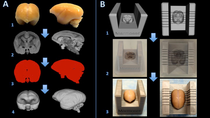
マーモセットの脳スライサーボックスを作成する1.ワークフロー図 。脳をホルマリン(A1)で固定されており、T2強調MRIは、エッジあたり150マイクロメートル(A2)の等方性ボクセルで取得されています。画像を処理し、バイナリマスク(A3)を作成するために閾値処理されています。表面は、その後、3Dモデリングソフトウェア(A4)でレンダリングされます。スライサーテンプレートと脳モデルとのブーリアン減算は脳スライサー(B1)のデジタルモデルを作成します。脳スライサーボックスは、3Dプリンタ(B2)に印刷されています。脳は、その後、スライサーボックスの中にしっかりと配置されています切断(B3)。 この図の拡大版をご覧になるにはこちらをクリックしてください。
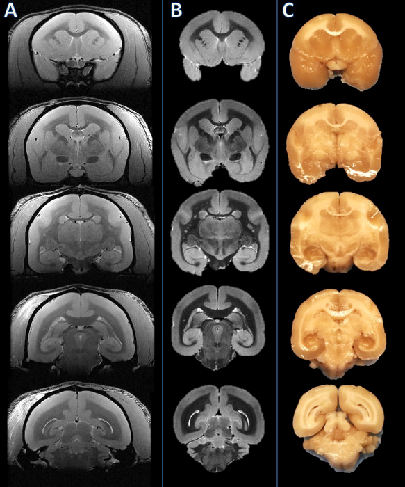
左から右へ図2: 生体内 MRI、死後MRI、および組織スラブ写真で 。スライス平面は、対応するin vivoでの MRIのスライス(A)に比べて視覚的に死後MRI(B)に基づいて設立されました。脳は、その後切断し、そして得られたスラブは、一貫した(C)であることが見出されました。 この図の拡大版をご覧になるにはこちらをクリックしてください。
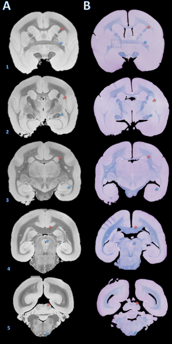
図3.高解像度の死後MRIおよび組織学セクションマッチング。スラブは、4μmの切片にミクロトームで切断し、パラフィンに包埋し、ファストブルーおよびクレシルバイオレット(B)で染色しました。次いで、切片を視覚的に脳構造(A)に基づいて、100ミクロンのT2 * - 重み付けMRIと一致しました。この画像を取得するための詳細は、プロトコルと表1の脳構造の補足セクションにあります:(1)赤い矢印=内部カプセル、青色の矢印=前交連。 (2)赤い矢印=被殻、青色の矢印=視索。 (3)赤色の矢印=尾状核、青色の矢印=海馬; (4)赤い矢印=脳梁、青色の矢印=中脳水道; (5)赤い矢印=下丘、青い矢印=錐体路。 B1の破線のボックスは、どちらかの脳の切断またはパラフィン包埋中に、エラーが左側の前交連の不一致につながる、Y軸周りのわずかな回転を引き起こしたスライスを示しています。 ご覧になるにはこちらをクリックしてください。この図の拡大版。
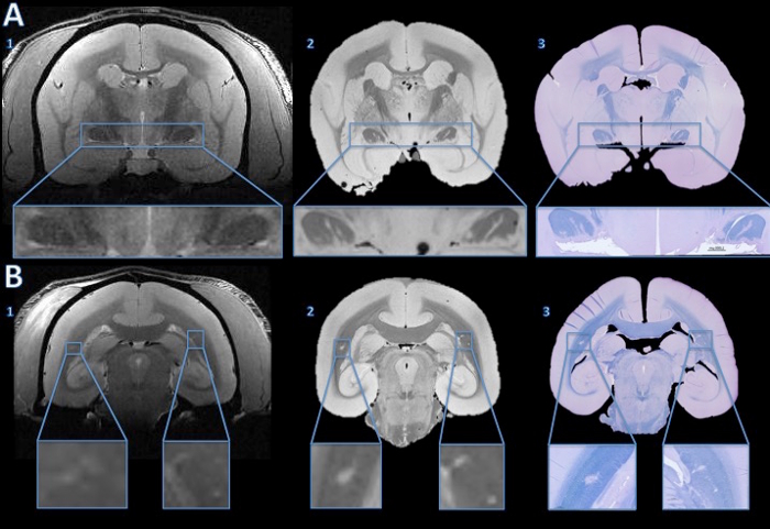
図4.組織学セクションにin vivoでの MRIの病変を追跡。 in vivoでの MRIは視神経管(A1)のいずれかに病変を示唆する異常hyperintensity信号のない説得力のある証拠を示しませんでした。しかし、高解像度の死後MRIは、両方の視神経管(A2)の明確なハイパー強烈な行を示しています。 4μmの組織学セクションのファーストブルー/クレシルバイオレット染色は、ex vivo MRIで見られる高強度領域は(A3)の脱髄していることを示しています。大脳白質では、in vivoでの MRIは微妙な左右対称hyperintensity(B1、インセットの拡大)を示しています。高信号領域は、高解像度の死後MRI(B2)の詳細は明らかです。 4μmの組織学セクションのLFB染色は、これらの領域は、(B3)の脱髄していることを示しています。ベースラインIと比較した後、nは生体内MRIとヘマトキシリン・アンド・エオシン染色は、右サイドは、解剖学的異常はなく、脱髄病変であると決定しました。 この図の拡大版をご覧になるにはこちらをクリックしてください。
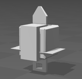
補足コードファイル。 Brain_Slicer_Parts_Marmoset.stl: このファイルをダウンロードするにはこちらをクリックしてください。 Brain_Slicer_Parts_Human.stl: このファイルをダウンロードするにはこちらをクリックしてください。 Cap_Insert.stl: このファイルをダウンロードするにはこちらをクリックしてください。
ディスカッション
ここで説明するプロトコルは、MRIおよび組織学のセクション間の正確な比較を可能にします。プロトコルは、例えば、マーモセットやげっ歯類などのヒトまたは小動物の脳に適用することができる統一フォーマットで提示されています。大(ヒト)に特異的な、脳が強調されている(非ヒト霊長類および齧歯類)小、および添付のビデオや数字の違いは、私たちは、マーモセットでアプリケーションを実証します。アプローチは簡単ですが、この方法は多くの工程だけでなく、ソフトウェアのいくつかのタイプを使用する必要があります。また、潜在的にこの方法の精度に影響を与えるいくつかの問題が言及することが重要です。
インビボ MRIの画質が重要な因子です。 MRIおよび組織学的デジタル画像間の画像解像度の不均衡を最小限に抑えるために、可能な限り最小のMRIボクセルサイズは、使用されるべきです。この概念はまた、死後MRIの画質に適用されます。増加したものの死後MRIにおける取得時間がはるかに高い画像解像度を可能にする、製剤は、気泡に関連する焦点信号抜け等の画像アーチファクトを導入することができます。これらのアーチファクトは、組織の領域を不明瞭だけでなく、その輪郭に影響を与えることができます。また、死後のMRI上の組織の寸法は、定着工程及び持続時間によって影響される可能性があります。 ex vivoでのMRI一致密接取得中スライス幾何設定で、解剖学的ランドマークを利用することによって近似することができるにインビボながらは、非線形登録がまだそれら二つのMRI画像を合わせてより高い精度に到達するのに必要であろう。
脳ホルダーとスライサーのデザインも重要なステップです。脳のデジタルモデルを作成する際に、平滑化アルゴリズムは、わずかに固定された脳のモデルを相対的に大きくすることが適用されます。これは、そのホルダーとスライサーに脳の容易な挿入を可能にし、ホルダーにシャープなエッジを低減します' sの輪郭。モデルが大きすぎる場合は、(例えば、5%以上)、脳は死後MRIおよび/または切片中に移動することがあります。別の重要な点は、小脳が適切に3D印刷オブジェクトの内部に配置されるように、脳モデルの設計を適応させることです。小脳は、剖検で脳の抽出中に損傷を受けたとき、これは特に困難な場合があります。
脳スライサーとホルダーを印刷する場合は、3Dプリンタの種類も慎重に選択する必要があります。いくつかのマルチインクジェットプリンタは、支持材料を除去するためにオーブンを用いて後処理を必要とします。これらのプリンタは、防水およびデスクトップ熱溶解積層法(FDM)のプリンタよりも比較的耐久性があるオブジェクトを生成することができますが、サポートを除去するための加熱処理は、わずかに脳の輪郭に対して完全に垂直ではないブレードギャップを作成し、ボックスをワープすることができます。
脳切片プロセスは、別の重要なステップです。目を切断する前に電子スラブへの全脳は、脳が脳スライサーの内側にしっかりと座っていることを確認することが重要です:わずかな圧力が脳に適用される動きがあってはなりません。これにより、ブレードが研究者によって設定された正確な位置で脳を切断できるようにするためであろう。切断時に連続し、バランスのとれた圧力は、両方のブレードホルダーに適用する必要があります。刃の切れ味と組織の剛性に応じて、わずかな横方向の切削運動は、平坦な切断面を維持するのに有利である可能性があります。
パラフィン包埋プロセスはまた、MRIおよび組織学との位置ずれの原因となることがあります。組織のスラブは、埋め込みプロセス中にカセットに対して平らに座っていない場合は、ミクロトームの切断面とスラブの表面の場所との間に傾きがあるでしょう。これは、すべての組織が露出した平面を検索するために使用できないセクションを切断する必要があります。傾きを補正するための一つの方法高等方性の解像度の死後MRIで観察面の角度を変化させることです。しかし、これは通常異方性解像度(典型的には厚の冠状切片)で取得されたin vivoでのMRI上で実行することはほぼ不可能です。
最後に、組織は、同様に(しわ、割れ、折りたたみ)スライドの準備中にホルマリン固定期間およびパラフィン包埋(収縮)の間にいくつかの変形を体験することができます。これらの変形のいくつかは、スライド上に転送する前に水浴中で4~5μmの切片を置くことによって補正することができます。他の変形は、部分的に、死後MRI画像に学的デジタル画像の変形可能な画像coregistrationを実行することによって解決することができます。それにもかかわらず、慎重かつ熟練の練習で変形を最小限に抑えることが組織学セクションにMRIボリュームに一致する最も効果的なアプローチです。
結論として、ここで紹介する方法は、INVを可能にします正確にMRI所見の根底にある病理を評価するestigators。より一般的には、同定および/またはそのような炎症または再ミエリン化のような特定の病理学的プロセスを標的とする調査研究のための新規MRIバイオマーカーを検証するための有望なアプローチです。
開示事項
The authors declare that they have no competing financial interests.
謝辞
The Intramural Research Program of NINDS supported this study. We thank the NIH Functional Magnetic Resonance Imaging Facility. We thank Jennifer Lefeuvre and Cecil Chern-Chyi Yen for assistance with postmortem MRI acquisition. We thank John Ostuni and the Section on Instrumentation Core Facility for assistance with 3D printing. Figure 1 of this work used snapshots from MeshLab, a tool developed with the support of the 3D-CoForm project.
資料
| Name | Company | Catalog Number | Comments |
| 7T/30cm USR AVIII Bruker MRI | Bruker Biospin | ||
| 38 mm Bruker Biospin volume coil | Bruker Biospin | ||
| Fomblin | Solvay Solexis | ||
| 50 ml Falcon Centrifuge Tubes, Polypropylene, Sterile | Corning | 21008-951 | |
| Fisherbrand Gauze Sponges | Fisher Scientrific | 13-761-52 | |
| Parafilm M All-Purpose Laboratory Film | Bemis | ||
| Leica RM2235 rotary microtome | Leica | ||
| Leica Disposable Blades, low profile (819) | Leica | ||
| Cresyl Violet Acetate, 0.1% Aqueous | Electron Microscopy Sciences | 26089-01 | |
| Luxol Fast Blue, 0.1% in 95% Alcohol | Electron Microscopy Sciences | 26056-15 | |
| ETOH | |||
| Ultimaker 2 Extended | Ultimaker | ||
| .75 kg Official Ultimaker Branded PLA Filament, 2.85 mm, Silver Metallic | Ultimaker | ||
| Axio Observer.Z1 | Zeiss | ||
| Zen 2 (Blue Edition) | Zeiss | ||
| Netfabb Professional 5.0.1 | Netfabb | http://www.netfabb.com/professional.php | |
| Meshmixer 10.9.332 | Autodesk | http://www.meshmixer.com/download.html | |
| Mipav 7.2 | NIH CIT | http://mipav.cit.nih.edu | |
| Cura | Ultimaker | https://ultimaker.com/en/products/cura-software |
参考文献
- Evans, A. C., Frank, J. A., Antel, J., Miller, D. H. The role of MRI in clinical trials of multiple sclerosis: comparison of image processing techniques. Ann Neurol. 41 (1), 125-132 (1997).
- 't Hart, B. A., van Kooyk, Y., Geurts, J. J. G., Gran, B. The primate autoimmune encephalomyelitis model; a bridge between mouse and man. Ann Clin Transl Neurol. 2 (5), 581-593 (2015).
- Ontaneda, D., Hyland, M., Cohen, J. A. Multiple sclerosis: new insights in pathogenesis and novel therapeutics. Annu Rev Med. 63, 389-404 (2012).
- Guy, J. R., Sati, P., Leibovitch, E., Jacobson, S., Silva, A. C., Reich, D. S. Custom fit 3D-printed brain holders for comparison of histology with MRI in marmosets. J Neurosci Methods. 257, 55-63 (2016).
- Breen, M. S., Lazebnik, R. S., Wilson, D. L. Three-dimensional registration of magnetic resonance image data to histological sections with model-based evaluation. Ann Biomed Eng. 33 (8), 1100-1112 (2005).
- Dauguet, J., et al. Three-dimensional reconstruction of stained histological slices and 3D non-linear registration with in-vivo MRI for whole baboon brain. J Neurosci Methods. 164 (1), 191-204 (2007).
- McGrath, D. M., Vlad, R. M., Foltz, W. D., Brock, K. K. Technical note: fiducial markers for correlation of whole-specimen histopathology with MR imaging at 7 tesla. Med Phys. 37, 2321-2328 (2010).
- Schormann, T., Zilles, K. Three-Dimensional linear and nonlinear transformations: An integration of light microscopical and MRI data. Hum Brain Mapp. 6, 339-347 (1998).
- Jiang, L., et al. Combined MR, fluorescence and histology imaging strategy in a human breast tumor xenograft model. NMR Biomed. 26 (3), 285-298 (2013).
- Absinta, M., et al. Postmortem magnetic resonance imaging to guide the pathologic cut: individualized, 3-dimensionally printed cutting boxes for fixed brains. J Neuropathol Exp Neurol. 73 (8), 780-788 (2014).
- Gaitán, M. I., et al. Perivenular brain lesions in a primate multiple sclerosis model at 7-tesla magnetic resonance imaging. Mult Scler. 20 (1), 64-71 (2014).
転載および許可
このJoVE論文のテキスト又は図を再利用するための許可を申請します
許可を申請さらに記事を探す
This article has been published
Video Coming Soon
Copyright © 2023 MyJoVE Corporation. All rights reserved