
Aby wyświetlić tę treść, wymagana jest subskrypcja JoVE. Zaloguj się lub rozpocznij bezpłatny okres próbny.
Method Article
Interlinked Macroporous 3D Scaffolds from Microgel Rods
W tym Artykule
Podsumowanie
Microgel rods with complementary reactive groups are produced via microfluidics with the ability to interlink in aqueous solution. The anisometric microgels jam and interlink into stable constructs with larger pores compared to spherical-based systems. Microgels modified with GRGDS-PC form macroporous 3D constructs that can be used for cell culture.
Streszczenie
A two-component system of functionalized microgels from microfluidics allows for fast interlinking into 3D macroporous constructs in aqueous solutions without further additives. Continuous photoinitiated on-chip gelation enables variation of the microgel aspect ratio, which determines the building block properties for the obtained constructs. Glycidyl methacrylate (GMA) or 2-aminoethyl methacrylate (AMA) monomers are copolymerized into the microgel network based on polyethylene glycol (PEG) star-polymers to achieve either epoxy or amine functionality. A focusing oil flow is introduced into the microfluidic outlet structure to ensure continuous collection of the functionalized microgel rods. Based on a recent publication, microgel rod-based constructs result in larger pores of several hundred micrometers and, at the same time, lead to overall higher scaffold stability in comparison to a spherical-based model. In this way, it is possible to produce higher-volume constructs with more free volume while reducing the amount of material required. The interlinked macroporous scaffolds can be picked up and transported without damage or disintegration. Amine and epoxy groups not involved in interlinking remain active and can be used independently for post-modification. This protocol describes an optimized method for the fabrication of microgel rods to form macroporous interlinked scaffolds that can be utilized for subsequent cell experiments.
Wprowadzenie
To study complex cooperative cell behavior in 3D constructs, scaffold platforms need to show consistent performance in reproducibility, have suitable geometry for cell migration, and, at the same time, allow certain flexibility in terms of parameter alteration to investigate their influence on the living tissue1. In recent years, the concept of macroporous annealed particles (MAP), first described by Segura et al., developed into an efficient and versatile platform for 3D scaffold production2. The tailored composition of the microgels, which are the building blocks of the final 3D scaffold, predefines properties such as the stiffness of the construct, the selective chemical reactivity of the gel network, and the final pore size of the scaffold2,3,4,5,6. Cell adhesive peptides as cues for scaffold-cell interactions are incorporated into the polymer network of the microgels to allow for cell attachment and can be varied to investigate their specific effects on cells in culture. The 3D scaffolds are stabilized by interlinking of the annealed injectable microgels due to covalent or supramolecular bonds, resulting in robust and defined constructs for cell culture2,3,5,7,8.
Microfluidics has established itself as one of the most accurate and adaptable methods for the preparation of defined granular hydrogels9. The possibility of producing larger quantities of the required building blocks in a continuous process while maintaining their chemical, mechanical, and physical monodispersity contributes substantially to the suitability of this process. Furthermore, the size and shape of the produced microgels can be manipulated by various methods such as batch emulsions, microfluidics, lithography, electrodynamic spraying, or mechanical fragmentation, which determine the geometry of the building blocks and, thus, the 3D structure of the final scaffold1,10.
Recently, the concept of macroporous 3D scaffolds composed of functionalized microgel rods that rapidly interlink in aqueous solutions without further additives has been reported11. The anisotropy of microgel rods resulted in higher porosities and pore distributions with larger pore sizes compared to employing spherical microgels in this study11. In this way, less material creates larger pores with a variety of different pore geometries while maintaining the stability of the 3D scaffold. The system consists of two types of microgel rods with complementary primary amine and epoxy functional groups that are consumed within the interlinking reaction when coming in contact with each other. The functional groups that do not participate in the interlinking process remain active and can be used for selective post-modification with cell adhesive peptides or other bioactive factors. Fibroblast cells attach, spread, and proliferate when cultured inside the 3D scaffolds, first growing on the microgel surface and filling most of the macropores after 5 days. A preliminary co-culture study of human fibroblasts and human umbilical vein endothelial cells (HUVECs) showed promising results for the formation of vessel-like structures within the interlinked 3D scaffolds11.
Protokół
1. Required material and preparations for microfluidics
- For the described microfluidic procedure, use 1 mL and 5 mL glass syringes and syringe pumps. On-chip droplet formation is observed via an inverted microscope equipped with a high-speed camera.
- Create the microfluidic chip design (Figure 1B) using a computer-aided design software and produce a master template as already reported12.
- Achieve controlled UV-irradiation using a self-constructed UV-LED (λ = 365 nm, spot diameter ~4.7 mm) providing irradiance at 957 mW/cm2 through a 0.13 mm thick cover glass.
NOTE: Take into account possible local heat generation by the UV-LED during irradiation. If this is the case, ensure sufficient cooling by external airflow.
2. Microfluidic device production
NOTE: The microfluidic device production is based on a previous publication13.
- Prepare 20 g of a 10:1 (by mass) mixture of polydimethylsiloxane (PDMS) and curing agent. Mix vigorously for 3 min.
- Mix 60 mg of Oil Red O in 2.0 g of toluene. Add 50 µL of Oil Red O in toluene solution to the PDMS mixture. Mix until there is homogeneous color distribution to decrease undesired light scattering and keep the spot size focused during on-chip gelation.
- Remove the bubbles by placing the mixture into a desiccator equipped with a vacuum pump.
- Cast the PDMS mixture into the master template to a height of 5-5.5 mm and degas again.
- Allow the PDMS to cure for 18 h at room temperature to avoid diazo dye degradation.
- Cut out the PDMS structure and punch inlet and outlet holes into the structure using a line core sampling tool (0.77 mm inner diameter, 1.07 mm outer diameter).
- Wash the PDMS and cover glass with isopropanol and deionized water repeatedly 5x and, subsequently, remove the liquid via pressured air or nitrogen flow after each washing step.
- Treat the dry glass and PDMS together in a plasma oven at 0.2 mbar, with an oxygen flow of 20 mL/min for 60 s at 100 W, and connect directly to bind the glass and PDMS together to form the microfluidic device.
NOTE: Avoid bending the PDMS structure during the binding process to minimize channel structure deformation. - To render the channels of the microfluidic chip hydrophobic, place the device together with 50 µL of trichloro-(1H,1H,2H,2H-perfluoroctyl)-silane in a desiccator under vacuum overnight (close the connection to the pump after decreasing the vapor pressure). Rinse the outside of the device with hydrofluoroether.
CAUTION: Perform these steps in a fume hood and avoid any contact with the perfluoro silane. Use a glass vacuum desiccator sealed with grease. Clean the desiccator thoroughly before using for other purposes.
3. Solution preparation for microfluidics
- For the continuous oil phase, mix paraffin oil and hexadecane (1:1 v/v) and add 8% (w/w) of a non-ionic surfactant. Fill one 1 mL (first oil, Figure 1) and one 5 mL (second oil, Figure 1) glass syringe.
- Prepare the prepolymer solutions for the disperse phase in brown glass vials to prevent photoinitiator decomposition and unintended gelation.
- Amine component prepolymer solution containing GRGDS-PC
- For a 300 µL solution, weigh out 33.3 mg of star-polyethylene glycol-acrylate (sPEG-AC) and 3.03 mg of lithium phenyl-2,4,6-trimethylbenzoylphosphinate (LAP).
- Dissolve 18.74 mg of 2-aminoethyl methacrylate hydrochloride (AMA) in 1.5 mL of deionized water and pass the solution through a syringe filter (0.20 µm pore size).
NOTE: AMA is hygroscopic and should be discarded as soon as the solid forms lumps in the storage container. - Prepare sterile 36 mM GRGDS-PC aliquots in water and keep at −20 °C until use.
- Use 291.7 µL of the AMA solution to dissolve sPEG-AC and LAP, and add 8.3 µL of the GRGDS-PC solution. Take up the solution with a 1 mL glass syringe and protect from light using aluminum foil.
- Epoxy component prepolymer solution
- For a 300 µL solution, weigh 33.3 mg of star-polyethylene glycol-acrylate (sPEG-AC), 3.03 mg of LAP and dissolve in 300 µL of deionized water. Add 2.4 mg of glycidyl methacrylate (GMA).
NOTE: Vigorous shaking accelerates GMA dissolving. Take up the solution with a 1 mL glass syringe and protect from light using aluminum foil.
- For a 300 µL solution, weigh 33.3 mg of star-polyethylene glycol-acrylate (sPEG-AC), 3.03 mg of LAP and dissolve in 300 µL of deionized water. Add 2.4 mg of glycidyl methacrylate (GMA).
- Amine component prepolymer solution containing GRGDS-PC
4. Production and purification of amine and epoxy functionalized microgel rods

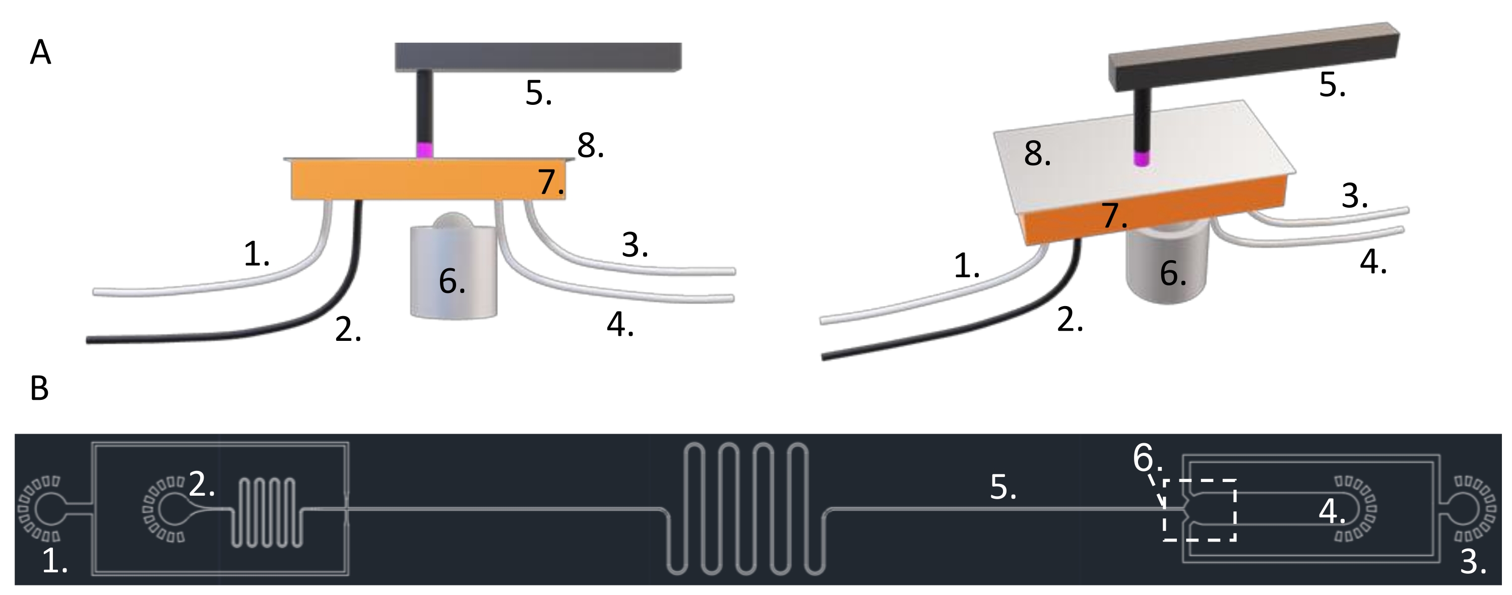
Figure 1: Arrangement of the microfluidic on-chip gelation assembly. (A) Front view and angled view of the component arrangement during microfluidics. (B) Microfluidic chip design used for on-chip gelation of microgel rods. (1) PE tube to the first oil inlet. (2) Light-protected PE tube to the disperse phase inlet. (3) PE tube to the second oil inlet. (4) PE tube from the outlet to the product collection container. (5) UV lamp and irradiation location on the straight 80 µm channel near the outlet. (6) Microscope objective/observation position. (7) Colored PDMS component of the microfluidic device. (8) Cover glass bonded to the PDMS. Please click here to view a larger version of this figure.
- Insert the needles into the PE tubes and remove the gas from the syringe and the tube.
- Insert a PE tube into the outlet for product collection.
- Place all the glass syringes in the syringe pumps and insert each tubing end into the corresponding inlet (Figure 1).
NOTE: Protect the prepolymer tubing from light via aluminum foil or a black tube to avoid unintentional gelation. - Focus the microscope on the oil-water cross-section.
- Start the first oil syringe pump (flow rate = 100-200 µL/h) to fill the channel with oil first to prevent channel wetting by the disperse phase.
- Decrease the first oil flow rate to 30 µL/h and start the prepolymer syringe pump (flow rate = 100-200 µL/h) until the dispersed aqueous phase can be observed at the cross-section.
- Set the prepolymer flow rate to 30 µL/h and focus the microscope on the outlet.
- Start the second oil syringe pump (flow rate of 300 µL/h) and wait until the flow regime is stable.
- Place the outlet tube in a collection container.
NOTE: Place the end of the tube in the upper part of the container to avoid a pressure increase due to the accumulation of the product over time. - Set the UV irradiation system such that the irradiance is in the range of 900-1000 mW/cm2 (used irradiance = 957 mW/cm2) and the irradiation spot is in the straight channel part before the outlet (Figure 1B).
NOTE: Make sure to not irradiate near the oil-water cross-section to avoid clogging the channel. For additional protection, cover the channel structures prior to the irradiation spot on the top of the unit. - Before UV irradiation, adjust the flow rates of the prepolymer and the first oil to achieve the desired aspect ratio in the range of 3.0 to 4.5, and set the irradiation time of the dispersed phase to ~2.3 s, depending on the size of the irradiation spot.
- Start UV irradiation and, if necessary, adjust the flow rates again according to the previous subsection.
NOTE: Observe the production at the beginning and monitor for stable flow behavior in the outlet and the uniformity of the microgel rods. The second oil flow can be adjusted to optimize product transport within the outlet. - Change the collection container and note the product collection start time and flow rates.
NOTE: Protect the product from dust. Stop collecting before any syringe runs low on solution. - To end collection, remove the collection container, noting the time. Stop irradiation and all the syringe pumps.
- Wash the product subsequently 5x each with n-hexane, isopropanol, and deionized water. Remove the supernatant after rod sedimentation.
NOTE: After each solution addition, disperse the product carefully and wait 10 min before replacing the solvent, considering molecular diffusion. Replace the isopropanol gradually with water to prevent the rods from floating to the surface of the liquid. Multiple additional washing steps with water decrease the remaining isopropanol traces.
5. Macroporous scaffold formation
- Determine the number of microgel rods per dispersion volume for the epoxy and amine functionalized samples.
- Adjust the number of epoxy and amine functionalized samples by dilution or concentration to a similar value between 1,000-5,000 rods/100 µL.
NOTE: Use a centrifuge at ~2,000 x g for 5-10 s to speed up the sedimentation of the microgel rods. If the number of rods per dispersion volume is low, rod-interlinking may result in smaller rod clusters instead of one stable construct. If the number of rods per dispersion volume is high, the mixing quality of the two components will be compromised. - Transfer the first component (~1,200 rods) dispersion into a conical 1.5 mL or 2 mL transparent vial.
- Add the second component in a controlled manner in a continuous operation (100 µL pipette). After addition, mix the contents directly using the pipette to take up liquid and add it again. The interlinked structure forms within seconds during mixing.
NOTE: If multiple clusters form instead of one coherent structure, recheck the number of microgel rods per volume or provide more controlled mixing of the two components.
6. Cell adhesive post-modification
- Calculate the theoretical number of epoxy groups in the interlinked structure based on the flow rate of the dispersed polymer phase, the number of microgels collected during a specific time, and the dilution factor of the microgel dispersion used for scaffold formation.
NOTE: Approximate the theoretical number of epoxy groups per scaffold by the following equation.


nth: Theoretical amount of substance
cGMA: GMA concentration in prepolymer solution
Q: Flow rate of prepolymer solution - Add GRGDS-PC solution to the interlinked structure to modify all remaining epoxy groups with the cell adhesive peptide bearing a free amine and thiol (n[theoretical epoxy groups]/n[GRGDS-PC] = 1). Leave at room temperature overnight.
- Remove the unreacted molecules by washing with deionized water and removing the supernatant.
7. Sterilization and transfer into cell culture media
- Reduce the water level to just submerge the interlinked scaffold.
- Open the vial and irradiate with UV light of λ = 250-300 nm. Close the vial and transfer the vial onto a clean bench. Wash 1x with sterile water.
- Replace the water in the vial with cell culture media and allow for equilibration for 5 min. Repeat this with fresh cell culture media 2x.
- Transfer the macroporous scaffold into a cell culture well plate for the experiment by pouring or using a spatula.
Wyniki

Figure 2: Macroporous crosslinked scaffold structure. (A) 3D projection of a 500 µm confocal microscopy Z-stack of the interlinked macroporous scaffold. Scale bar represents 500 µm. (B) Interlinked scaffold composed of ~10,000 microgel rods on a cover glass taken directly out of water. Scale bar repre...
Dyskusje
One of the critical steps in this protocol is the quality of the 2-aminoethyl methacrylate (AMA) used as the comonomer for primary amine functionalization. The AMA should be a fine-grained and preferably colorless powder delivered in a gas-tight brown glass container. One should avoid using greenish and lumpy material, as it significantly impairs the gelation reaction and negatively affects the reproducibility of the results. In case of poor gelation and unstable microgel rods, one can consider changing the supplier.
...Ujawnienia
The authors assure that there are no conflicts of interest.
Podziękowania
We express our gratitude to the coauthors of our previous work this methodology is based on, Céline Bastard, Luis P. B. Guerzoni, Yonca Kittel, Rostislav Vinokur, Nikolai Born, and Tamás Haraszti. We gratefully acknowledge funding from the Deutsche Forschungsgemeinschaft (DFG) within the project B5 and C3 SFB 985 "Functional Microgels and Microgel Systems". We acknowledge funding from the Leibniz Senate Competition Committee (SAW) under the Professorinnenprogramm (SAW-2017-PB62: BioMat). We sincerely acknowledge funding from the European Commission (EUSMI, 731019). This work was performed in part at the Center for Chemical Polymer Technology (CPT), which was supported by the EU and the federal state of North Rhine-Westphalia (grant EFRE 30 00 883 02).
Materiały
| Name | Company | Catalog Number | Comments |
| ABIL EM 90 | Evonik | 144243-53-8 | non-ionic surfactant |
| 2-Aminoethyl methacrylate hydrochloride | TCI Chemicals | A3413 | >98.0%(T)(HPLC) |
| 8-Arm PEG-acrylate 20 kDa | Biochempeg Scientific Inc. | A88009-20K | ≥ 95 % |
| AutoCAD 2019 | Autodesk | computer-aided design (CAD) software; modeling of microfluidic designs | |
| CHROMAFIL MV A-20/25 syringe filter | XH49.1 | pore size 0.20 µm; Cellulose Mixed Esters (MV) | |
| Cover glass | Marienfeld-Superior | type No. 1 | |
| EMS Swiss line core sampling tool 0.75 mm | Electron Microscopy Sciences | 0.77 mm inner diameter, 1.07 mm outer diameter | |
| Ethanol absolut | VWR Chemicals | ||
| FL3-U3-13Y3M 150 FPS series high-speed camera | FLIR Systems | ||
| Fluoresceinamine isomer I | Sigma-Aldrich | 201626 | |
| Fluorescein isothiocyanate | Thermo Fisher Scientific | 46424 | |
| 25G x 5/8’’ 0,50 x 16 mm needles | BD Microlance 3 | ||
| Glycidyl methacrylate | Sigma-Aldrich | 779342 | ≥97.0% (GC) |
| GRGDS-PC | CPC Scientific | FIBN-015A | |
| Hamilton 1000 Series Gastight syringes | Thermo Fisher Scientific | 10772361/10500052 | PFTE Luer-Lock |
| Hexane | Sigma-Aldrich | 1,04,367 | |
| Lithium phenyl-2,4,6-trimethylbenzoylphosphinate | Sigma-Aldrich | 900889 | ≥95 % |
| Motic AE2000 trinocular microscope | Ted Pella, Inc. | 22443-12 | |
| Novec 7100 | Sigma-Aldrich | SHH0002 | |
| Oil Red O | Sigma-Aldrich | O9755 | |
| Paraffin | VWR Chemicals | 24679320 | |
| Pavone Nanoindenter Platform | Optics11Life | ||
| Phosphate buffered saline | Thermo Fisher Scientific | AM9624 | |
| Polyethylene Tubing 0.38×1.09mm medical grade | dropletex | ID 0.38 mm OD 1.09 mm | |
| 2-Propanol | Sigma-Aldrich | 190764 | ACS reagent, ≥99.5% |
| Protein LoBind Tubes | Eppendorf | 30108132 | |
| Pump 11 Pico Plus Elite Programmable Syringe Pump | Harvard Apparatus | ||
| RPMI 1640 medium | Gibco | 11530586 | |
| SYLGARD 184 silicone elastomer kit | Dow SYLGARD | 634165S | |
| Trichloro-(1H,1H,2H,2H-perfluoroctyl)-silane | Sigma-Aldrich | 448931 | |
| UVC LED sterilizing box | UVLED Optical Technology Co., Ltd. | 9S SZH8-S2 |
Odniesienia
- Daly, A. C., Riley, L., Segura, T., Burdick, J. A. Hydrogel microparticles for biomedical applications. Nature Reviews Materials. 5 (1), 20-43 (2020).
- Griffin, D. R., Weaver, W. M., Scumpia, P. O., Di Carlo, D., Segura, T. Accelerated wound healing by injectable microporous gel scaffolds assembled from annealed building blocks. Nature Materials. 14 (7), 737-744 (2015).
- Xin, S., Wyman, O. M., Alge, D. L. Assembly of PEG microgels into porous cell-instructive 3D scaffolds via thiol-ene click chemistry. Advanced Healthcare Materials. 7 (11), 1800160 (2018).
- Truong, N. F., et al. Microporous annealed particle hydrogel stiffness, void space size, and adhesion properties impact cell proliferation, cell spreading, and gene transfer. Acta Biomaterialia. 94, 160-172 (2019).
- Sheikhi, A., et al. Microfluidic-enabled bottom-up hydrogels from annealable naturally-derived protein microbeads. Biomaterials. 192, 560-568 (2019).
- de Rutte, J. M., Koh, J., Di Carlo, D. Scalable high-throughput production of modular microgels for in situ assembly of microporous tissue scaffolds. Advanced Functional Materials. 29 (25), 1900071 (2019).
- Hsu, R. -. S., et al. Adaptable microporous hydrogels of propagating NGF-gradient by injectable building blocks for accelerated axonal outgrowth. Advanced Science. 6 (16), 1900520 (2019).
- Caldwell, A. S., Campbell, G. T., Shekiro, K. M. T., Anseth, K. S. Clickable microgel scaffolds as platforms for 3D cell encapsulation. Advanced Healthcare Materials. 6 (15), 1700254 (2017).
- Chen, Z., et al. Advanced microfluidic devices for fabricating multi-structural hydrogel microsphere. Exploration. 1 (3), 20210036 (2021).
- Qazi, T. H., et al. Anisotropic rod-shaped particles influence injectable granular hydrogel properties and cell invasion. Advanced Materials. 34 (12), 2109194 (2022).
- Rommel, D., et al. Functionalized microgel rods interlinked into soft macroporous structures for 3D cell culture. Advanced Science. 9 (10), 2103554 (2022).
- Guerzoni, L. P. B., et al. Cell encapsulation in soft, anisometric poly(ethylene) glycol microgels using a novel radical-free microfluidic system. Small. 15 (20), 1900692 (2019).
- Krüger, A. J. D., et al. Compartmentalized jet polymerization as a high-resolution process to continuously produce anisometric microgel rods with adjustable size and stiffness. Advanced Materials. 31 (49), 1903668 (2019).
- Darling, N. J., et al. Click by click microporous annealed particle (MAP) scaffolds. Advanced Healthcare Materials. 9 (10), 1901391 (2020).
- Lutzweiler, G., Ndreu Halili, ., Engin Vrana, N. The overview of porous, bioactive scaffolds as instructive biomaterials for tissue regeneration and their clinical translation. Pharmaceutics. 12 (7), 602 (2020).
- Dang, H. P., et al. 3D printed dual macro-, microscale porous network as a tissue engineering scaffold with drug delivering function. Biofabrication. 11 (3), 035014 (2019).
- Highley, C. B., Song, K. H., Daly, A. C., Burdick, J. A. Jammed microgel inks for 3D printing applications. Advanced Science. 6 (1), 1801076 (2019).
Przedruki i uprawnienia
Zapytaj o uprawnienia na użycie tekstu lub obrazów z tego artykułu JoVE
Zapytaj o uprawnieniaThis article has been published
Video Coming Soon
Copyright © 2025 MyJoVE Corporation. Wszelkie prawa zastrzeżone