
Aby wyświetlić tę treść, wymagana jest subskrypcja JoVE. Zaloguj się lub rozpocznij bezpłatny okres próbny.
Method Article
Tools for Surface Treatment of Silicon Planar Intracortical Microelectrodes
W tym Artykule
Podsumowanie
The present protocol describes tools for handling silicon planar intracortical microelectrodes during treatments for surface modification via gas deposition and aqueous solution reactions. The assembly of the components used to handle the devices throughout the procedure is explained in detail.
Streszczenie
Intracortical microelectrodes hold great therapeutic potential. But they are challenged with significant performance reduction after modest implantation durations. A substantial contributor to the observed decline is the damage to the neural tissue proximal to the implant and subsequent neuroinflammatory response. Efforts to improve device longevity include chemical modifications or coating applications to the device surface to improve the tissue response. Development of such surface treatments is typically completed using non-functional "dummy" probes that lack the electrical components required for the intended application. Translation to functional devices requires additional consideration given the fragility of intracortical microelectrode arrays. Handling tools greatly facilitate surface treatments to assembled devices, particularly for modifications that require long procedural times. The handling tools described here are used for surface treatments applied via gas-phase deposition and aqueous solution exposure. Characterization of the coating is performed using ellipsometry and x-ray photoelectron spectroscopy. A comparison of electrical impedance spectroscopy recordings before and after the coating procedure on functional devices confirmed device integrity following modification. The described tools can be readily adapted for alternative electrode devices and treatment methods that maintain chemical compatibility.
Wprowadzenie
Neuroprosthetic devices aim to restore impaired or absent sensory and motor abilities in a wide range of patient populations, including those with spinal cord injury, Amyotrophic Lateral Sclerosis (ALS), cerebral palsy, and amputations1,2,3. Intracortical microelectrodes (IMEs) can establish a communication pathway between cortical neurons and the devices used to control neuroprosthetics. A distinct advantage of intracortical microelectrodes is their capability to record neural signals at the high spatial and temporal resolution, which is preferred for subsequent signal processing and control of brain-computer interfaces4,5. Unfortunately, the performance of intracortical microelectrodes dramatically reduces within months to a year following implantation2,6,7,8. The loss of signal quality and stability negatively affects the application of the technology.
A significant contributor to the observed performance decline is the biotic response to implantation-associated tissue damage and chronic neuroinflammation9,10,11. Implantation of IMEs inflicts damage on brain tissue, resulting in the release of signaling molecules that initiate cascades of reactionary cellular defense processes. Chronic interfacing exacerbates the foreign body response, leading to sustained neuroinflammation that damages tissue proximal to the device; often recognized as symptoms of neuroinflammation, scarring, and local neurodegeneration contributing to the decline of the recording of the signal quality12,13,14,15. Comprising a dense conglomerate of astrocytes with entrained activated microglia and macrophages, the scar that encapsulates the electrode creates an unfavorable local environment with reduced material transport and local accumulation of inflammatory factors16,15,16,17,18.
Many studies have described the brain's response to intracortical microelectrodes or approaches to mitigate the response7. Research and development into improving the tissue response have involved a range of strategies, including modifications to the overall structure, surface topology, materials, and coatings application. These efforts intend to minimize damage sustained from the implantation event, introduce a more favorable interface between the device and proximal cells, or reduce the tissue strain after devices are implanted7. Methods specifically targeting the chronic biologic response have led to several bioactive coatings that aim to stabilize the implantation site and chemically promote cell health. Examples include conductive polymers such as poly(ethylene dioxythiophene) (PEDOT)19,20, carbon nanotubes21, hydrogels22, and the addition of bioactive molecules and drugs to target specific cellular processes23,24,25. Our research group, in particular, have explored many mechanisms to promote a reduction of the inflammatory response to implanted microelectrodes including, but not limited to, minimizing the trauma associated with device implantation26, minimizing the device/tissue stiffness mismatch27,28,29,30,31,32,33, optimizing sterilization procedures34,35, reducing oxidative stress/damage28,36,37,38,39,40,41,42, exploring alternative electrode materials43, and mimicking the nano-architecture of the natural extracellular matrix44,45,46. Recent interest is the development of biomimetic surface coatings to mitigate the neuroinflammatory response at the microelectrode tissue interface directly39.
Modification of the interface offers the unique benefit of directly targeting the wound and the proximal tissue necessary for signal recording. A surface treatment that promotes healing without exacerbating the immune response can benefit the lifetime of quality recording and remove limitations in realizing the therapeutic and research potential of intracortical microelectrodes. The presented work details methods for applying surface treatments to microelectrode arrays that require extended reaction times while accommodating the fragility of the devices. The presented technique is intended to share surface modification methods to functional devices where the device cannot be handled throughout the treatment application. The tools are presented for handling non-functional dummy probes and functional silicon planar microelectrode arrays.
The presented approach to modify the electrode surface allows for the secure suspension of non-functional dummy probes or functional silicon planar electrode arrays for gas-phase deposition and reaction with aqueous solutions. Several 3D printed pieces are used to handle these fragile devices (Figure 1 and Figure 2). An example is provided of a procedure that utilizes both gas and solution phase steps for the surface modification with an antioxidative coating involving the immobilization of Mn(III)tetrakis (4-benzoic acid) porphyrin (MnTBAP). MnTBAP is a synthetic metalloporphyrin possessing antioxidant properties with demonstrated mediation of inflammation47,48. The provided example on functional silicon planar electrode arrays validates an update to a previously reported protocol for non-functional devices40. The adaptation of a gas phase deposition technique from Munief et al. supports the protocol's compatibility with functional electrodes49. The gas-phase deposition is utilized to amine functionalize the surface in preparation for the aqueous reaction involving carbodiimide crosslinker chemistry to immobilize the active MnTBAP. The handling methodology developed here is provided as a platform that can be modified to accommodate other coatings and similar devices.
The protocol illustrates the approach using non-functional dummy probes comprising a silicon shank and 3D printed tab with similar dimensions to the functional silicon planar electrode arrays. The connector packaging of the device is considered analogous to the 3D printed tab of the non-functional dummy probe in the provided instruction.

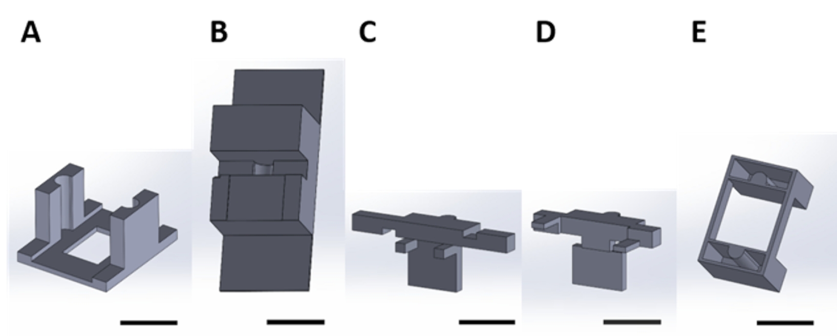
Figure 1: 3D printed pieces for handling functional devices during the gas-phase deposition in a vacuum desiccator. (A) The structure's base includes holders for 1 cm x 1 cm sample silicon squares (top arrow) and holes for securing to desiccator plate (bottom arrow). (B) The plate is used to secure the suspension of devices. From here onward, each piece in this figure will be referred to as either piece 1A or 1B. Scale bar = 1 cm. Please click here to view a larger version of this figure.

Figure 2: 3D printed pieces for handling functional devices for the surface reaction occurring in the aqueous solution. (A) Guide piece to be glued to the lid of the culture plate. (B) Benchtop pieces used to stabilize pieces (C) and (D) while assembling. (C) and (D) together secure the suspension of devices for placement in the well plate, and (E) further secures pieces (C) and (D) to the well plate lid. From here onward, individual pieces in each panel of this figure will be referred to as piece numbers corresponding to the panel number of this figure. Scale bar = 1 cm. Please click here to view a larger version of this figure.
Protokół
All the coding files for 3D printing are provided in Supplementary Coding Files 1-16. The analysis provided in the Representative results is described using commercially acquired functional silicon planar electrode arrays (see Table of Materials).
1. Handling assembly for gas-phase deposition in a vacuum desiccator
NOTE: The assembled apparatus for handling and holding devices during gas-phase deposition is shown in Figure 3. Steps 1.1-1.8 describe the procedure required to place the devices into the apparatus for deposition (Figure 4A).

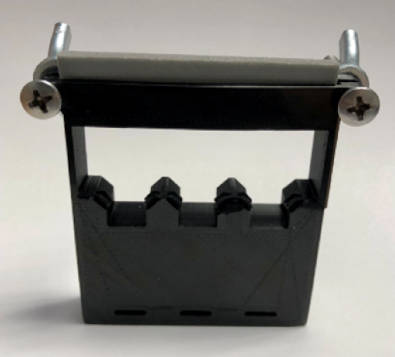
Figure 3: Assembly of 3D printed pieces for handling functional devices during gas-phase deposition. The assembly is pictured without samples to be coated. Screws and wing nuts are used to fasten pieces 1A and 2B together. Please click here to view a larger version of this figure.

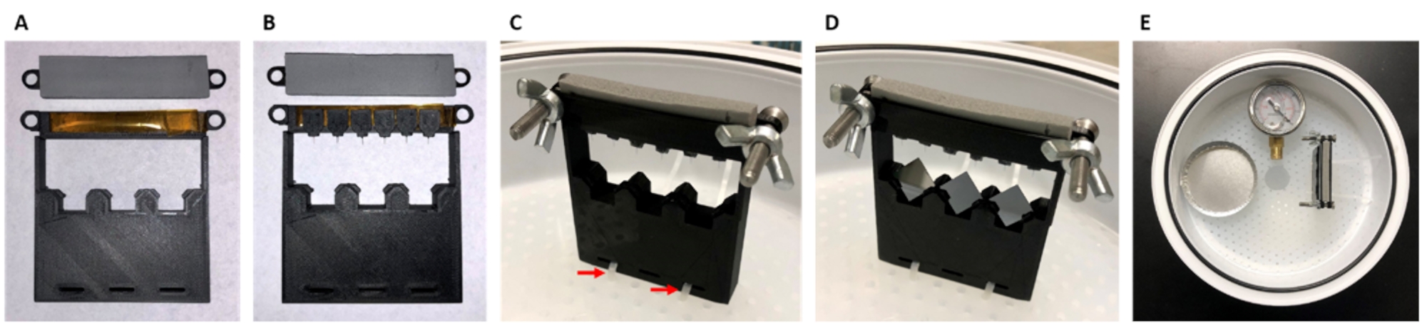
Figure 4: Image of assembly and placement of samples to be coated. This scheme describes the handling of functional devices during gas-phase deposition secured within a vacuum desiccator. (A) Double-sided polyimide tape placed on piece 1A and foam tape placed on 1B. (B) Devices secured onto tape. (C) Screws and wing nuts are used to fasten pieces 1B to 1A, and the assembly is attached to the desiccator tray using zip cable ties (red arrows). (D) 1 cm x 1 cm silicon square samples are placed into respective holders. (E) The aluminum weigh dish and pressure gauge are placed into the desiccator in the orientation shown. Please click here to view a larger version of this figure.
- For surface treatment, acquire 1 cm x 1 cm square samples of the devices' substrate material.
- For silicon samples (selected for this protocol), cut the silicon wafer into 1 cm x 1 cm squares using a wafer dicing machine (see Table of Materials).
- Print or acquire pieces 1A (Figure 1A, Supplementary Coding File 1, Supplementary Coding File 2) and 1B (Figure 1B, Supplementary Coding File 3, Supplementary Coding File 4).
- Attach double-sided polyimide tape to piece 1A and attach 1/8" thick foam strip with one-side adhesive to piece 1B.
- Adhere the connector packaging of the device to the tape on piece 1A.
NOTE: The ideal orientation of the connector on the tape will leave the shank suspended over the edge, as shown in Figure 4B. - Secure piece 1A and piece 1B together (Figure 4C). Align the holes and secure using stainless steel screws and wing nuts (see Table of Materials).
- Using zip ties, fasten the assembly to the vacuum desiccator tray using the holes in the bottom of piece 1A as shown in Figure 4C.
- If applicable, place square material samples into the slits at the bottom of the frame (Figure 4D). Here, 1 cm x 1 cm square silicon wafer diced samples are used as an example.
NOTE: The exact material will need to match the substrate of the treated device, which will vary depending on the device. - Complete the gas-phase deposition by placing the solution into an appropriate receptacle within the vacuum desiccator opposite and in line with the secured assembly.
NOTE: Aluminum weigh dishes were used as receptacles for the (3-Aminopropyl)triethoxysilane (APTES) deposition, as an example here.- Place a vacuum gauge (see Table of Materials) within the desiccator to record the exact pressure. Position the port of the desiccator lid near the secured assembly and in line with the solution (Figure 4E).
NOTE: Further details regarding this method of gas-phase deposition are described in a previously published Reference49.
- Place a vacuum gauge (see Table of Materials) within the desiccator to record the exact pressure. Position the port of the desiccator lid near the secured assembly and in line with the solution (Figure 4E).
2. Handling assembly for surface reaction via aqueous solution
NOTE: The components and assembled apparatus for handling and holding devices during aqueous phase deposition and surface treatment are illustrated in Figures 5-7. The following steps will detail the procedure required to place the devices into the apparatus for deposition and treatment.

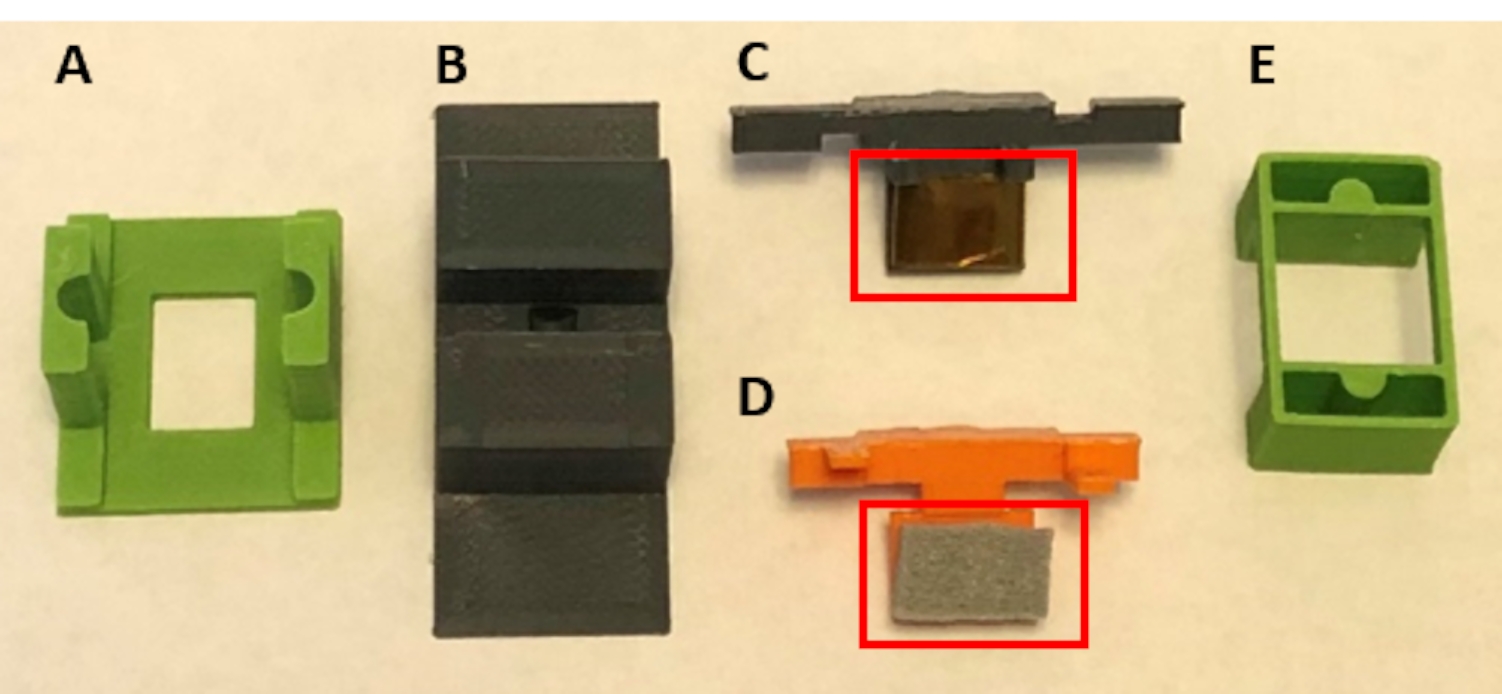
Figure 5: Assembly of 3D printed pieces for handling functional devices for the surface reaction occurring in aqueous solution. (A) Guide piece to be glued to the lid of the culture plate. (B) The benchtop piece was used to stabilize pieces (C) and (D) while assembling. (C) and (D) together secure the suspension of devices for placement in the well plate. (E) further secures pieces (C) and (D) to the well plate lid. Double-sided polyimide tape was placed on the lower portion of (C), and foam tape was placed on the lower portion of (D) (both boxed in red). Please click here to view a larger version of this figure.

Figure 6: Cell culture plate lid constructed with 6 guides (piece 2A). Please click here to view a larger version of this figure.

Figure 7: Sequence for securing and loading probes for solution reaction. The color of the parts was changed in this figure for clarity within the image. These are the same parts as Figure 5 and Figure 6. (A) Piece 2C is placed into piece 2B, and the device is secured to the taped portion of 2C. (B) Piece 2D fits into piece 2C to create an assembly that suspends the device shank. (C) The assembly of 2C, 2D, and the device is carefully positioned onto the lid of the well plate using the guide. (D) Piece 2E fits on top of the assembly to further secure the lid. Please click here to view a larger version of this figure.
- Construct a lid for the well plate to suspend the electrode array of the device in solution (Figure 6). This protocol describes the use of a 24-well plate.
- Cut rectangular holes 19 mm x 10.5 mm into the lid of the well plate using a laser cutter or manually with a box cutter. Match the number of holes to the number of devices desired for treatment.
NOTE: For ease of assembly, it is recommended to treat six devices per well plate, or at minimum, place holes over non-adjacent wells (Figure 6). - Print or acquire the appropriate number of guides (piece 2A (Figure 2A), Supplementary Coding File 5, Supplementary Coding File 6).
- Use cyanoacrylate adhesive to secure guides to the lid. Align the rectangular holes in the guides and lids while gluing to ensure the guide's rectangular hole is unobstructed, as shown in Figure 6.
- Cut rectangular holes 19 mm x 10.5 mm into the lid of the well plate using a laser cutter or manually with a box cutter. Match the number of holes to the number of devices desired for treatment.
- Fill the well plate with the desired solution at locations where treatment will occur. For example purposes, the solution comprises EDC and Sulfo-NHS (see Table of Materials) in MES buffer.
NOTE: The volume of the solution will depend on the electrode device's dimensions. For Michigan-style microelectrode arrays (see Table of Materials) with low-profile connectors of 8.6 mm and shank length of 3 mm, there is ~9 mm clearance50. Using 2 mL of solution will allow for the shank of the device to be fully submerged while keeping the remainder of the device out of the reaction solution.- If substrate samples are being used to confirm surface treatment, place square material samples in a well of the plate and submerge them in the reaction solution.
- Securely suspend the devices (see Table of Materials) in a well plate. The sequence is shown in Figure 7.
- Tape piece 2B (Figure 2B, Supplementary Coding File 7, Supplementary Coding File 8) to a benchtop (Figure 7A).
- Place double-sided polyimide tape to cover the base of piece 2C (Figure 2C, Supplementary Coding File 9, Supplementary Coding File 10).
- Place 1/8" foam tape with single-side adhesive to cover the base of piece 2D (Figure 2D, Supplementary Coding File 11, Supplementary Coding File 12).
- Fit piece 2C into the groove of piece 2B (Figure 7A).
- Adhere the connector packaging of the device onto the tape, oriented, so the length of the device shank is suspended (Figure 7B).
- Secure the device by sliding piece 2D (shown in orange in Figure 7) into piece 2C. This assembly effectively secures the device between the tool pieces (Figure 7B).
- Holding the edges of the assembly, carefully lift to remove from piece 2A.
- Fit the assembly into the lid by aligning the outward-facing semicircles on pieces 2C and 2D with the corresponding guides on piece 2A (shown in green in Figure 7C).
- Secure assembly placement by press-fitting piece 2E (Figure 2E) over the guides (shown in green in Figure 7D, Supplementary Coding File 13, Supplementary Coding File 14).
- For reactions that benefit from continuous mixing of the solution, agitate the well plate. Transfer the assembled well plate to a shaker table and run at speeds under 100 rpm.
- If multiple solution-based reactions or wash steps are desired, carefully transfer the lid to a new well plate with desired solution(s) distributed to the appropriate wells.
NOTE: Step 2.4 is optional. - Remove devices from the well plate.
- Tape piece 2B to a benchtop.
- Remove piece 2E from the lid.
- Carefully remove the assembly holding the device from the well plate.
- Orient the assembly, so that piece 2C faces the benchtop and piece 2D faces upward. The shank of the device needs to be parallel to the benchtop. Fit piece 2C of the assembly into piece 2B as was completed previously (step 2.3.4) when fitting together the assembly.
- Separate piece 2D from piece 2C by carefully pulling them apart. Apply slight pressure on the tabs of piece 2C into the bench to provide stability for this task.
NOTE: The tabs of 2C are longer than that of 2D to facilitate this handling. - Use forceps to hold onto the device's connector packaging to remove from the tape and transfer the device to the desired storage container.
Wyniki
To demonstrate the use of the handling components, the described methodology was implemented to adapt the immobilization of an oxidant mediator to activated silicon. The application of this chemistry to IMEs to reduce oxidative stress was devised by Potter-Baker et al. and demonstrated on non-functional silicon dummy probes40. This surface treatment immobilizes the antioxidant, MnTBAP, to UV/ozone activated silicon surface via amine functionalization followed by carbodiimide crosslinking ...
Dyskusje
The described protocol was designed for the surface treatment of silicon planar microelectrode arrays. The 3D printed tools are customized to Michigan-style microelectrode arrays with low-profile connectors50. Non-functional probes were assembled by adhering a silicon probe to 3D printed tabs using a biocompatible adhesive. The 3D printed tabs were designed with similar dimensions to the connectors incorporated on the commercially available devices used. Files for the 3D printed tabs are available...
Ujawnienia
The contents do not represent the views of the US Department of Veterans Affairs, the National Institutes of Health, or the United States Government.
Podziękowania
This study was supported in part by Merit Review Award IRX002611 (Capadona) and Research Career Scientist Award IK6RX003077 (Capadona) from the United States (US) Department of Veterans Affairs Rehabilitation Research and Development Service. Additionally, this work was also supported in part by the National Institute of Health, National Institute of Neurological Disorders and Stroke R01NS110823 (Capadona/Pancrazio), and the National Science Foundation Graduate Research Fellowship Program (Krebs).
Materiały
| Name | Company | Catalog Number | Comments |
| 1-[3-(Dimethylamino)propyl]-3-ethylcarbodiimide methiodide (EDC) | Sigma-Aldrich | 165344-1G | Solid, stored desiccated at -20 °C |
| 15 mL Conical Centrifuge Tubes | Fisher Scientific | 14-959-70C | |
| 18 Pound Solid Nylon Cable/Zip Ties | Cole-Parmer | EW-06830-66 | Length 4 inches |
| 2-(N-Morpholino)ethanesulfonic acid (MES) | Sigma-Aldrich | 4432-31-9 | Solid |
| 3-aminopropyltriethoxysilane (APTES) | Sigma-Aldrich | 440140-100ML | Liquid, container with Sure/Seal |
| 50 mL Conical Centrifuge Tubes | Fisher Scientific | 14-959-49A | |
| Aluminum foil | Fisher Scientific | 01-213-103 | |
| Aluminum weighing dishes | Fisher Scientific | 08-732-102 | Diameter 66 mm |
| Bel-Art Vacuum Desiccator | Fisher Scientific | 08-594-15B | |
| Corning Costar TC-Treated Multiple Well Plates | Millipore Sigma | CLS3527-100EA | 24-well plate, polystyrene |
| Cyanoacrylate Adhesive | LocTite | N/A | |
| Digital Microscope | Keyence | VHX-S750E | |
| Disco DAD3350 Dicing Saw | Disco | DAD3350 | Used to cut silicon wafer into 1 cm x 1 cm samples |
| Double-Sided Polyimide Tape | Kapton Tape | PPTDE-1/4 | ¼” x 36 yds. |
| EP21LVMed – low viscosity, two component epoxy compound | Masterbond | EP21LVMed | Meets USP Class VI certification, Passes ISO 10993-5 for cytotoxicity |
| Epilog Fusion Pro 48 Laser Machine | Epilog | N/A | CO2 laser |
| Foam tape | XFasten | N/A | 1/8" Thick |
| Gamry Interface 1010E Potentiostat | Gamry | 992-00129 | |
| High precision 45° curved tapered very fine point tweezers/forceps | Fisher Scientific | 12-000-131 | |
| Lab tape | Fisher Scientific | 15-901-10L | |
| Mn(III)tetrakis (4-benzoic acid) porphyrin (MnTBAP) | EMD Millipore | 475870-25MG | Solid, stored at -20 °C |
| N-Hydroxysulfosuccinimide sodium salt, ≥98% (HPLC) | Sigma-Aldrich | 56485-250MG | Solid, stored desiccated at 4°C |
| Platinum clad niobium mesh anode | Technic | N/A | Clad with 125μ” of platinum on one side, framed in titanium with (1) 1” x 6” titanium strap centered on one 6” dimension |
| Silicon Planar Microelectrode Array, 16 Channel | NeuroNexus | A1x16-3mm-100-177-CM16LP | Electrode site material is iridium, shank thickness is 15 μm |
| Silicon Wafer | University Wafer | 1575 | Diameter 100 mm, p-type, boron-doped, 100 oriented, resistivity 0.01-0.02 Ohm-cm, thickness 525 um, single side polished, prime grade |
| Silver/silver Chloride reference electrode | Gamry Instruments | 930-00015 | |
| Solidworks | N/A | ||
| Stainless Steel Phillips Flat Head Screws | McMaster Carr | 96877A629 | #8-32, 1 1/2", fully threaded |
| Type I deionized water | ChemWorld | CW-DI1-20 | |
| Ultimaker 3 3D printer | Ultimaker | N/A | |
| Ultimaker Cura | Ultimaker | N/A | 3D printing software |
| Ultimaker NFC ABS Filament | Dynamism, Inc. | 1621 | 2.85 mm |
| Ultimaker NFC PLA Filament | Dynamism, Inc. | 1609 | 2.85 mm |
| Vacuum Gauge Vacuum Gauge | Measureman Direct | N/A | Glycerin Filled, 2-1/2” Dial Size, ¼”NPT, -30” Hg/-100kpa-0 |
| Wing nuts | Everbilt | 934917 | #8-32, zinc plated |
Odniesienia
- Donoghue, J. Bridging the brain to the world: A perspective on neural interface systems. Neuron. 60 (3), 511-521 (2008).
- Ajiboye, A. B., et al. Restoration of reaching and grasping movements through brain-controlled muscle stimulation in a person with tetraplegia: a proof-of-concept demonstration. The Lancet. 398 (10081), 1821-1830 (2017).
- Ereifej, E. S., et al. Neural engineering: the process, applications, and its role in the future of medicine. Journal of Neural Engineering. 16 (6), 063002 (2019).
- Nicolas-Alonso, L. F., Gomez-Gil, J. Brain computer interfaces, a review. Sensors (Basel). 12 (2), 1211-1279 (2012).
- Leuthardt, E. C., Schalk, G., Moran, D., Ojemann, J. G. The emerging world of motor neuroprosthetics: a neurosurgical perspective. Neurosurgery. 59 (1), 1-14 (2006).
- Barrese, J. C., et al. Failure mode analysis of silicon-based intracortical microelectrode arrays in non-human primates. Journal of Neural Engineering. 10 (6), 066014 (2013).
- Jorfi, M., Skousen, J. L., Weder, C., Capadona, J. R. Progress towards biocompatible intracortical microelectrodes for neural interfacing applications. Journal of Neural Engineering. 12 (1), 011001 (2015).
- Prasad, A., et al. Comprehensive characterization and failure modes of tungsten microwire arrays in chronic neural implants. Journal of Neural Engineering. 9 (5), 056015 (2012).
- Hermann, J. K., Capadona, J. R. Understanding the role of innate immunity in the response to intracortical microelectrodes. Critical Reviews in Biomedical Engineering. 46 (4), 341-367 (2018).
- Ravikumar, M., et al. The roles of blood-derived macrophages and resident microglia in the neuroinflammatory response to implanted intracortical microelectrodes. Biomaterials. 35 (28), 8049-8064 (2014).
- Sawyer, A. J., et al. The effect of inflammatory cell-derived MCP-1 loss on neuronal survival during chronic neuroinflammation. Biomaterials. 35 (25), 6698-6706 (2014).
- Prasad, A., Sanchez, J. C. Quantifying long-term microelectrode array functionality using chronic in vivo impedance testing. Journal of Neural Engineering. 9 (2), 026028 (2012).
- Salatino, J. W., Ludwig, K. A., Kozai, T. D. Y., Purcell, E. K. Glial responses to implanted electrodes in the brain. Nature Biomedical Engineering. 1 (11), 862-877 (2017).
- McConnell, G. C., et al. Implanted neural electrodes cause chronic, local inflammation that is correlated with local neurodegeneration. Journal of Neural Engineering. 6 (5), 056003 (2009).
- Rennaker, R. L., Miller, J., Tang, H., Wilson, D. A. Minocycline increases quality and longevity of chronic neural recordings. Journal of Neural Engineering. 4 (2), 1-5 (2007).
- Carnicer-Lombarte, A., Chen, S. T., Malliaras, G. G., Barone, D. G. Foreign body reaction to implanted biomaterials and its impact in nerve neuroprosthetics. Frontiers in Bioengineering and Biotechnology. 9, 622524 (2021).
- Roitbak, T., Sykova, E. Diffusion barriers evoked in the rat cortex by reactive astrogliosis. Glia. 28 (1), 40-48 (1999).
- Polikov, V. S., Tresco, P. A., Reichert, W. M. Response of brain tissue to chronically implanted neural electrodes. Journal of Neuroscience Methods. 148 (1), 1-18 (2005).
- Cui, X., Martin, D. C. Electrochemical deposition and characterization of poly(3,4-ethylenedioxythiophene) on neural microelectrode arrays. Sensors and Actuators B: Chemical. 89 (1), 92-102 (2003).
- Ludwig, K. A., Uram, J. D., Yang, J., Martin, D. C., Kipke, D. R. Chronic neural recordings using silicon microelectrode arrays electrochemically deposited with a poly(3,4-ethylenedioxythiophene) (PEDOT) film. Journal of Neural Engineering. 3 (1), 59-70 (2006).
- Keefer, E. W., Botterman, B. R., Romero, M. I., Rossi, A. F., Gross, G. W. Carbon nanotube coating improves neuronal recordings. Nature Nanotechnology. 3 (7), 434-439 (2008).
- Kim, D. -. H., Wiler, J. A., Anderson, D. J., Kipke, D. R., Martin, D. C. Conducting polymers on hydrogel-coated neural electrode provide sensitive neural recordings in auditory cortex. Acta Biomaterialia. 6 (1), 57-62 (2010).
- He, W., McConnell, G. C., Bellamkonda, R. V. Nanoscale laminin coating modulates cortical scarring response around implanted silicon microelectrode arrays. Journal of Neural Engineering. 3 (4), 316-326 (2006).
- Azemi, E., Lagenaur, C. F., Cui, X. T. The surface immobilization of the neural adhesion molecule L1 on neural probes and its effect on neuronal density and gliosis at the probe/tissue interface. Biomaterials. 32 (3), 681-692 (2011).
- Zhong, Y., Bellamkonda, R. V. Controlled release of anti-inflammatory agent alpha-MSH from neural implants. Journal of Controlled Release. 106 (3), 309-318 (2005).
- Shoffstall, A. J., et al. Potential for thermal damage to the blood-brain barrier during craniotomy: implications for intracortical recording microelectrodes. Journal of Neural Engineering. 15 (3), 034001 (2018).
- Bedell, H. W., et al. Understanding the effects of both CD14-meditated innate immunity and device/tissue mechanical mismatch in the neuroinflammatory response to intracortical microelectrodes. Frontiers in Neuroscience. 12, 772 (2018).
- Nguyen, J. K., et al. Influence of resveratrol release on the tissue response to mechanically adaptive cortical implants. Acta Biomaterialia. 29, 81-93 (2016).
- Sridharan, A., Nguyen, J. K., Capadona, J. R., Muthuswamy, J. Compliant intracortical implants reduce strains and strain rates in brain tissue in vivo. Journal of Neural Engineering. 12 (3), 036002 (2015).
- Nguyen, J. K., et al. Mechanically-compliant intracortical implants reduce the neuroinflammatory response. Journal of Neural Engineering. 11, 056014 (2014).
- Harris, J. P., et al. In vivo deployment of mechanically adaptive nanocomposites for intracortical microelectrodes. Journal of Neural Engineering. 8 (4), 046010 (2011).
- Shoffstall, A. J., et al. Characterization of the neuroinflammatory response to Thiol-ene/Acrylate shape memory polymer coated intracortical microelectrodes. Micromachines. 10, 486 (2018).
- Simon, D. M., et al. Design and demonstration of an intracortical probe technology with tunable modulus. Journal of Biomedical Materials Research. Part A. 105 (1), 159-168 (2017).
- Ravikumar, M., et al. The effect of residual endotoxin contamination on the neuroinflammatory response to sterilized intracortical microelectrodes. Journal of Materials Chemistry. B. 2 (17), 2517-2529 (2014).
- Ecker, M., et al. Sterilization of thiol-ene/acrylate based shape memory polymers for biomedical applications. Macromolecular Materials and Engineering. 302 (2), 160331 (2017).
- Ereifej, E. S., et al. Implantation of neural probes in the brain elicits oxidative stress. Frontiers in Bioengineering and Biotechnology. 6 (9), 1-12 (2018).
- Potter, K. A., et al. The effect of resveratrol on neurodegeneration and blood brain barrier stability surrounding intracortical microelectrodes. Biomaterials. 34 (29), 7001-7015 (2013).
- Potter, K. A., et al. Curcumin-releasing mechanically adaptive intracortical implants improve the proximal neuronal density and blood-brain barrier stability. Acta Biomaterialia. 10 (5), 2209-2222 (2014).
- Potter-Baker, K. A., Capadona, J. R. Reducing the "stress": Antioxidative therapeutic and material approaches may prevent intracortical microelectrode failure. ACS Macro Letters. 4 (3), 275-279 (2015).
- Potter-Baker, K. A., et al. Development of superoxide dismutase mimetic surfaces to reduce accumulation of reactive oxygen species for neural interfacing applications. Journal of Materials Chemistry B. 2 (16), 2248-2258 (2014).
- Potter-Baker, K. A., et al. Implications of chronic daily antioxidant administration on the inflammatory response to intracortical microelectrodes. Journal of Neural Engineering. 12 (4), 046002 (2015).
- Kim, Y., et al. Ventricular delivery of resveratrol improves microelectrode recording performance and reduces oxidative stress. Micromachines. 12, 1446 (2021).
- Deku, F., et al. Amorphous silicon carbide ultramicroelectrode arrays for neural stimulation and recording. Journal of Neural Engineering. 15 (1), 016007 (2018).
- Ereifej, E. S., et al. The neuroinflammatory response to nanopatterning parallel grooves into the surface structure of intracortical microelectrodes. Advanced Functional Materials. 28 (12), 1704420 (2018).
- Kim, Y., et al. Nano-architectural approaches for improved intracortical interface technologies. Frontiers in Neuroscience. 12, 456 (2018).
- Mahajan, S., et al. Towards standardization of electrophysiology and computational tissue strain in rodent intracortical microelectrode models. Frontiers in Bioengineering and Biotechnology. 8, 416 (2020).
- Suresh, M. V., et al. The protective role of MnTBAP in oxidant-mediated injury and inflammation in a rat model of lung contusion. Surgery. 154 (5), 980-990 (2013).
- Liu, D., Shan, Y., Valluru, L., Bao, F. Mn (III) tetrakis (4-benzoic acid) porphyrin scavenges reactive species, reduces oxidative stress, and improves functional recovery after experimental spinal cord injury in rats: comparison with methylprednisolone. BMC Neuroscience. 14 (1), 23 (2013).
- Munief, W. M., et al. Silane deposition via gas-phase evaporation and high-resolution surface characterization of the ultrathin siloxane coatings. Langmuir. 34 (35), 10217-10229 (2018).
- Hoogerwerf, A. C., Wise, K. D. A three-dimensional microelectrode array for chronic neural recording. IEEE Transactions on Biomedical Engineering. 41 (12), 1136-1146 (1994).
- Staros, J. V., Wright, R. W., Swingle, D. M. Enhancement by N-hydroxysulfosuccinimide of water-soluble carbodiimide-mediated coupling reactions. Analalytical Biochemistry. 156 (1), 220-222 (1986).
- Yuan, X., Wolf, N., Mayer, D., Offenhausser, A., Wordenweber, R. Vapor-phase deposition and electronic characterization of 3-Aminopropyltriethoxysilane self-assembled monolayers on silicon dioxide. Langmuir. 35 (25), 8183-8190 (2019).
- Montgomery, D. C. . Design and Analysis of Experiments. Eighth edition. , (2013).
- Shoffstall, A. J., Capadona, J. R. Bio-inspired materials and systems for neural interfacing. Current Opinions in Biomedical Engineering. 6, 110-119 (2018).
- Skousen, J. L., Tresco, P. A. . Neuroprosthetics. Theory and Practice 2nd Edition. , 259-299 (2017).
- Michelson, N. J., et al. multi-modal analysis uncovers complex relationship at the brain tissue-implant neural interface: new emphasis on the biological interface. Journal of Neural Engineering. 15 (3), 033001 (2018).
- Hofmann, U. G., Capadona, J. R. Editorial: Bridging the gap in neuroelectronic interfaces. Frontiers in Neuroscience. 14, 457 (2020).
- Usoro, J., Sturgill, B., Musselman, K., Capadona, J. R., Pancrazio, J. J. On the definition of 'chronic' for intracortical microelectrode array applications. Micromachines. 12 (8), 972 (2021).
- Thompson, C. H., Saxena, A., Heelan, N., Salatino, J., Purcell, E. K. Spatiotemporal patterns of gene expression around implanted silicon electrode arrays. Journal of Neural Engineering. 18 (4), 1741 (2021).
- Golabchi, A., Woeppel, K. M., Li, X., Lagenaur, C. F., Cui, X. T. Neuroadhesive protein coating improves the chronic performance of neuroelectronics in mouse brain. Biosensors and Bioelectronics. 155, 112096 (2020).
- Zheng, X. S., et al. A superoxide scavenging coating for improving tissue response to neural implants. Acta Biomaterialia. 99, 72-83 (2019).
- Lee, H. C., et al. Foreign body response to intracortical microelectrodes is not altered with dip-coating of Polyethylene Glycol (PEG). Frontiers in Neuroscience. 11, 513 (2017).
- Boehler, C., et al. Actively controlled release of Dexamethasone from neural microelectrodes in a chronic in vivo study. Biomaterials. 129, 176-187 (2017).
- Hess, A. E., et al. Development of a stimuli-responsive polymer nanocomposite toward biologically optimized, MEMS-based neural probes. Journal of Micromechanics and Microengineering. 21 (5), 054009 (2011).
Przedruki i uprawnienia
Zapytaj o uprawnienia na użycie tekstu lub obrazów z tego artykułu JoVE
Zapytaj o uprawnieniaPrzeglądaj więcej artyków
This article has been published
Video Coming Soon
Copyright © 2025 MyJoVE Corporation. Wszelkie prawa zastrzeżone