
A subscription to JoVE is required to view this content. Sign in or start your free trial.
Method Article
Ion-Exchange Membranes for the Fabrication of Reverse Electrodialysis Device
In This Article
Summary
We demonstrate the fabrication of a reverse electrodialysis device using a cation-exchange membrane (CEM) and anion-exchange membrane (AEM) for power generation.
Abstract
Reverse electrodialysis (RED) is an effective way to generate power by mixing two different salt concentrations in water using cation-exchange membranes (CEM) and anion-exchange membranes (AEM). The RED stack is composed of an alternating arrangement of the cation-exchange membrane and anion-exchange membrane. The RED device acts as a potential candidate for fulfilling the universal demand for future energy crises. Here, in this article, we demonstrate a procedure to fabricate a reverse electrodialysis device using laboratory-scale CEM and AEM for power production. The active area of the ion-exchange membrane is 49 cm2. In this article, we provide a step-by-step procedure for synthesizing the membrane, followed by the stack's assembly and power measurement. The measurement conditions and net power output calculation have also been explained. Furthermore, we describe the fundamental parameters that are taken into consideration for obtaining a reliable outcome. We also provide a theoretical parameter that affects the overall cell performance relating to the membrane and the feed solution. In short, this experiment describes how to assemble and measure RED cells on the same platform. It also contains the working principle and calculation used for estimating the net power output of the RED stack using CEM and AEM membranes.
Introduction
Energy harvesting from natural resources is an economical method that is environmentally friendly, thereby making our planet green and clean. Several processes have been proposed until now to extract energy, but reverse electrodialysis (RED) has an enormous potential to overcome the energy crisis issue1. Power production from Reverse electrodialysis is a technological breakthrough for the decarbonization of global energy. As the name suggests, RED is a reverse process, where the alternate cell compartment is filled with the high-concentrated salt solution and low-concentrated salt solution2. The chemical potential generated by the salt concentration difference across the ion-exchange membranes, collected from the electrodes at the compartment end.
Since the year 2000, many research articles have been published, providing insight into the RED theoretically and experimentally3,4. Systematic studies on the operation conditions and reliability studies under stress conditions improved the stack architecture and enhanced the overall cell performance. Several research groups have diverted their attention toward RED's hybrid application, such as RED with desalination process5, RED with solar power6, RED with reverse osmosis (RO) process5, RED with the microbial fuel cell7, and RED with the radiative cooling process8. As mentioned earlier, there is a lot of scope in implementing RED's hybrid application to solve the energy and clean water problem.
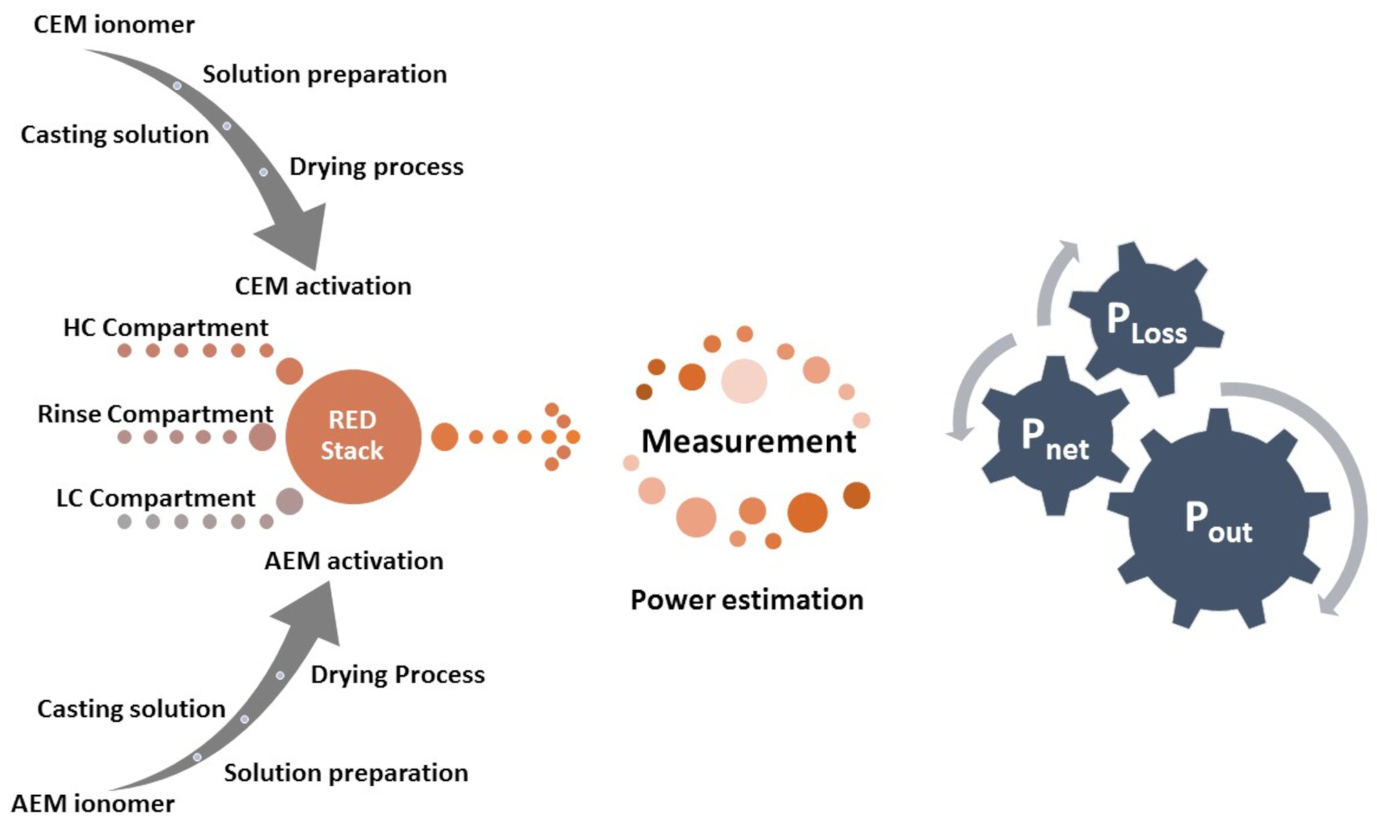
Several methods have been adopted to enhance the RED cell's performance and the membrane's ion-exchange capacity. Tailoring the cation-exchange membranes with different types of ions using sulfonic acid group (-SO3H), phosphonic acid group (-PO3H2), and carboxylic acid group (-COOH) is one of the effective ways to alter the physicochemical properties of the membrane. Anion-exchange membranes are tailored with ammonium groups ( )9. The high ionic conductivity of AEM and CEM without deteriorating the membrane's mechanical strength is the essential parameter for selecting an appropriate membrane for device application. The robust membrane under stress conditions provides mechanical stability to the membrane and enhances the device's durability. Here, a unique combination of high-performance free-standing sulfonated poly (ether ether ketone) (sPEEK) as cation-exchange membranes with FAA-3 as anion-exchange membranes are used in the RED application. Figure 1 shows the flow chart of the experimental procedure.

Figure 1: Procedure chart. The flow chart presents the procedure adopted for the preparation of ion-exchange membrane followed by the process for measurement of reverse electrodialysis. Please click here to view a larger version of this figure.
Protocol
1. Experimental requirement
- Purchase ion-exchange ionomer polymer, E-550 sulfonated-PEEK polymer fiber to prepare CEM and FAA-3 to prepare AEM. Ensure that all ionomer polymers are stored in a clean, dry, and dust-free environment before use.
- Use high purity (>99%) solvents, including N-Methyl-2- pyrrolidone with molecular weight 99.13 g mol-1 and N, N-Dimethylacetamide with molecular weight 87.12, for preparing homogeneous ionomer solution. Ensure all analytical grade chemicals and solvents are used for membrane preparation as received without any further purification.
- After the membranes' activation process, immediately immerse all membranes in a 0.5 M NaCl solution for better performance. After activation of both membranes, drying is not required. Water with resistivity is 18.2 MΩ at room temperature was used throughout the synthesis of the membrane.
- Characterize membrane properties using a dry membrane. The detailed description of the characterization techniques and their physicochemical properties such as ion-exchange capacity, ion-conductivity, thickness, thermal analysis, and surface morphology, are as presented in the literatures10,11.
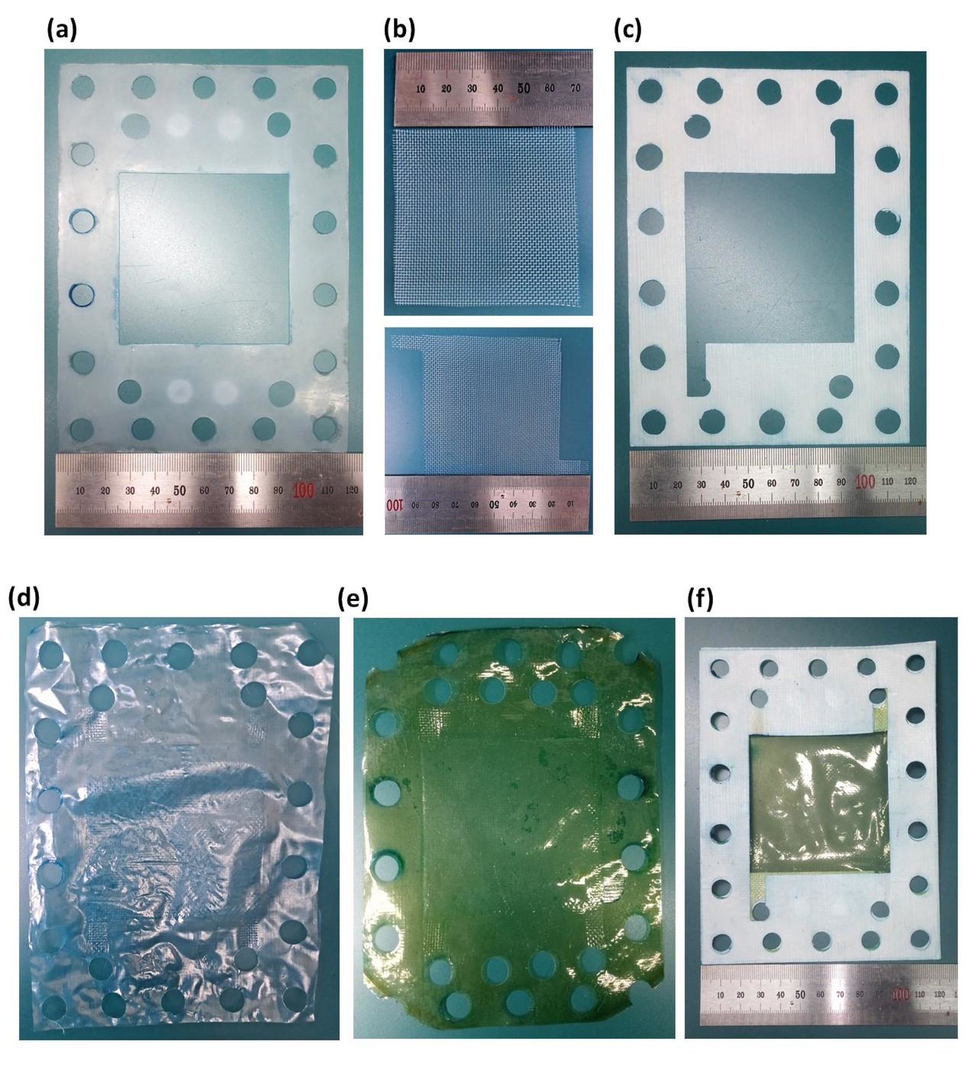
- Use a cutter to shape the membrane for CEM and AEM to the RED stack size with an active area of 49 cm2, as displayed in Figure 2.
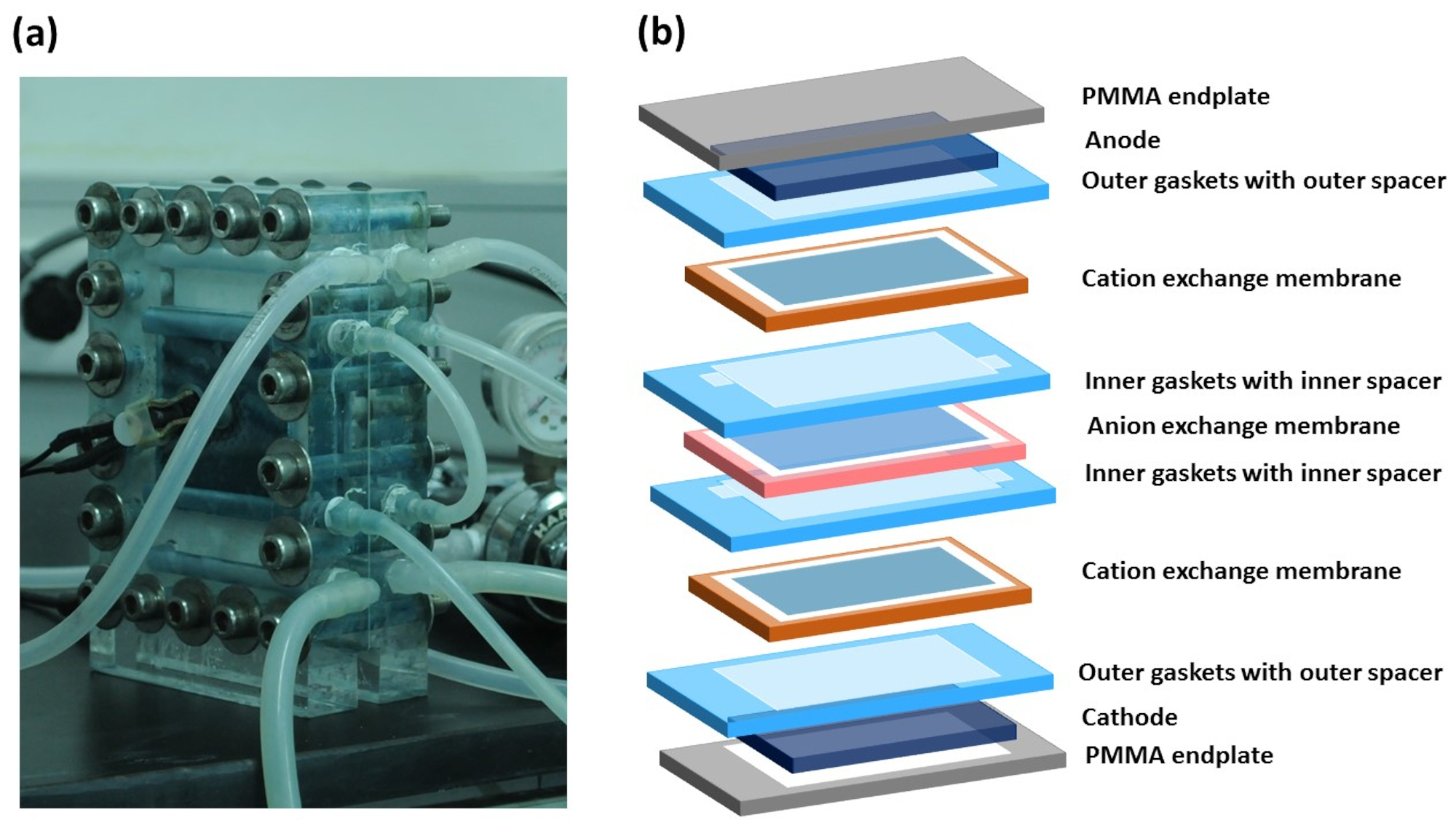
- For the RED stack fabrication, make an alternate CEM and AEM arrangement, separated by spacer and gasket; a real picture of the working RED stack is presented in Figure 3a, and its schematic diagram of each layer is illustrated in Figure 3b.
- First, place the PMMA plate facing electrode upside; now, place the rubber gasket and spacer on it, then place the CEM. After that, place the silicone gasket with the spacer on the CEM then place the AEM on it. Similarly, add the silicon gasket and spacer on the top of AEM followed by CEM. Now, place the end PMMA plate, rubber gasket, and spacer followed with tightening using screw and nut bolts.
- After assembling the RED stack, check the free flow of the high-concentration (HC), low-concentration (LC), and rinse the solutions one by one. Any crossflow or leakage is required to be eliminated before the measurement.
- Prior to the current and voltage measurement, monitor the flow rate of salt solutions and pressure gauge reading and make sure it gets stabilized. Make sure all the connections are in the exact place before the measurement starts. Avoid touching the RED stack and its connecting tubes while the measurement is running.
NOTE: HC and LC solution flow from their compartments to discard compartment through a peristaltic pump, pressure gauge, and RED stack, respectively. - Use galvanostat method for the measurement of current and voltage, the source meter instrument connected to the RED stack through crocodile clips.

Figure 2: Size and shape of the prepared membrane, gasket, and spacer for the fabrication of reverse electrodialysis. (a) outer silicone gasket, (b) outer spacer and inner spacer, (c) inner silicone gasket, (d) cation-exchange membrane, (e) anion-exchange membrane, and (f) gasket and membrane assembly. Please click here to view a larger version of this figure.

Figure 3: Reverse electrodialysis stack. (a) setup of reverse electrodialysis stack with connecting tubes, and (b) schematic illustration of different layers, including PMMA endplates, electrodes, gasket, spacer, CEM, and AEM. Please click here to view a larger version of this figure.
2. Ion-exchange membrane preparation
NOTE: The amount of precursor material was optimized for obtaining a membrane with 18 cm diameter and ~50 µm thickness.
- Cation-exchange membrane
- Take 5 wt% of sulfonated-PEEK fibers in a 250 mL round bottom flask and dissolve the fibers in Dimethylacetamide (DMAc) as a solvent having molecular weight 87.12 g mol-1. Shake the flask for 10 min so that all ionomer polymers settle down.
- Place a magnetic bar in the flask and then keep the mixture in the silicon oil bath, followed by vigorously stirring at 500 rpm for 24 h at 80 °C to obtain a homogenous solution.
- Filter the sulfonated-PEEK solution through a 0.45 µm pore size Polytetrafluoroethylene (PTFE) filter.
- After that, pour the filtered solution onto a circular glass dish with a diameter of 18 cm. Ensure that all air bubbles are removed using an air blower before placing the Petri dish in the oven.
- Place the Petri dish inside an oven for drying out the solution at 90 °C for 24 h, resulting in ~50 µm thick free-standing membrane. Do this for extracting free-standing membrane: To peel off the membrane from the Petri dish, fill the Petri dish with warm distill water (~60 °C) and let it stand for 10 min untouched. The free-standing membrane will automatically come out.
- For membrane activation, immerse the prepared free-standing membrane in 1 M sulfuric acid (H2SO4) aqueous solution, i.e., 98.08 g, in 1 L of distilled water, and incubate for 2 h at 80 °C.
NOTE: This step will ensure the removal of foreign particles and other chemicals such as solvents that will reduce the possibility of membrane from fouling. - Wash the soaked membrane with 1 L of distilled water for 10 min, at least three times at room temperature.
- Anion-exchange membrane
- Dissolve FAA-3 ionomer solution 10 wt.% in N-Methyl-2-pyrrolidone (NMP) solvent.
- Keep the solution for stirring at room temperature for 2 h at ~500 rpm.
- After that, filter the solution using the mesh with 100 µm pore size.
- Pour ~30 mL filtered solution into a circular glass Petri dish with a diameter of 18 cm. Ensure that all air bubbles were removed using an air blower before placing the glass Petri dish in the oven. The drying process takes place at 100 °C for 24 h.
- To obtain a free-standing membrane, pour hot distilled water into the glass Petri dish and keep it for at least 10 min. Now peel off the membranes and place in 1 liter of sodium hydroxide (NaOH) solution (concentration 1M and molecular weight 40 g mol-1) for 2 h.
- Then, wash the membrane thoroughly with 1 L of distilled water for 10 min, at least three times in ambient condition.
NOTE: All prepared membranes were stored in the 0.5 M NaCl solution overnight before using it in the RED stack. So that the membrane conductivity gets enhanced and can achieve stabilized output performance during the measurement of the RED stack. Table 1 describes the membrane properties10,11.
| Specification | Unit | CEM | AEM |
| Swelling degree | % | 5±1 | 1±0.5 |
| Charge density or Ion exchange capacity | meq/g | 1.8 | ~1.6 |
| Mechanical properties (Tensile strength) | MPa | >40 | 40-50 |
| Elongation to Break | % | ~42 | 30-50 |
| Young Modulus (MPa) | 1500±100 | 1000-1500 | |
| Conductivity at room temperature | S/cm | ~0.03 | ~0.025 |
| Permselectivity | % | 98-99 | 94-96 |
| Thickness | μm | 50±2 | 50±3 |
| Solvent | - | Dimethylacetamide (DMAc) | N-methyl-2-pyrrolidone (NMP) |
Table 1: Membranes properties. Summary of both cation-exchange and anion-exchange membrane properties.
3. Fabrication of reverse electrodialysis
- Assembly of RED stack
- Prepare a model solution using 0.6 M NaCl for high concentration (HC) and 0.01 M NaCl for low concentration (LC) compartments12.
NOTE: Here, river water is considered a low concentration salt solution, and seawater is represented as a high concentration salt solution. - Prepare 5 L of high concentration and low concentration solution in a large container connected with the tubes. Keep the solutions stirring at ambient conditions (room temperature) for at least 2 h before it is used in the RED stack.
- Prepare the mixture of 0.05 M of [Fe (CN)6]-3/ [Fe (CN)6]-4 and 0.3 M NaCl in 500 mL water as a rinse solution for RED.
- Connect all three solution containers with RED stack using rubber tubes through the peristaltic pump and pressure gauges. Use the tube of size L/S 16 for rinse solution, and use the tube of size L/S 25 for HC and LC solution.
- To make a RED stack, take two endplates made-up of polymethyl methacrylate (PMMA). Connect both endplates horizontally face to face with nuts, bolts, and washers using 25 Nm force using a digital wrench driver. The thickness of PMMA endplates 3 cm, and the path of the flow channels was designed in plates for HC, LC, and rinse solution by a driller2.
- Place two mesh electrodes made from metal Titanium (Ti) coated with a mixture of Iridium (Ir) and Ruthenium (Ru) in a 1:1 ratio and place at the end of the PMMA plates. Both end electrodes are connected with the crocodile clip of the source meter.
NOTE: Both PMMA end plates are equipped with mesh electrodes, both electrodes were layered with a square shape spacer, and the PMMA endplate covered with a rubber gasket facing inside. After that, CEM and AEM are placed alternatively, separated by silicone gasket and spacer, as shown in Figure 3. - Install silicon gaskets, polymer spacers, and ion-exchange membranes (CEM and AEM) layer by layer, as presented in the schematic diagram Figure 4 and Figure 5. Ensure the active area of electrodes, both membranes, outer and inner spacer, outer and inner gasket is 7 x 7 = 49 cm2.
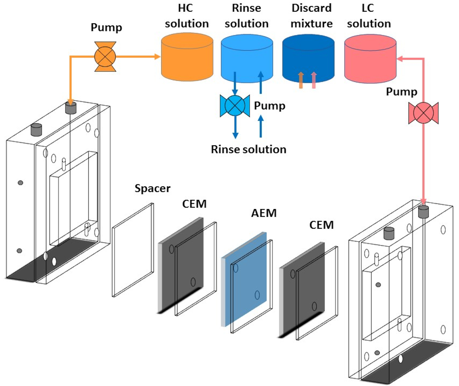
- Pass high-concentration and low-concentration solutions from respective compartments by peristaltic pumps, as displayed in the schematic diagram in Figure 4.
- Circulate the rinse solution in the outer electrode and membrane compartments in recirculation mode using peristaltic pumps. The flow rate used for the rinse solution is 50 mL min-1.
- Fixed flow rate is used for analyzing the performance of each membrane. In this experiment, we have used 100 mL min-1 through a peristaltic pump.
- Prepare a model solution using 0.6 M NaCl for high concentration (HC) and 0.01 M NaCl for low concentration (LC) compartments12.

Figure 4: Schematic representation of the tube connection with reverse electrodialysis stack. Connection of reverse electrodialysis with peristaltic pumps, high-concentration solution container, low-concentration solution container, rinse solution container, and discard solution container. It also shows the spacer's alignment with both an anion exchange membrane (AEM) and cation exchange membrane (CEM). Please click here to view a larger version of this figure.

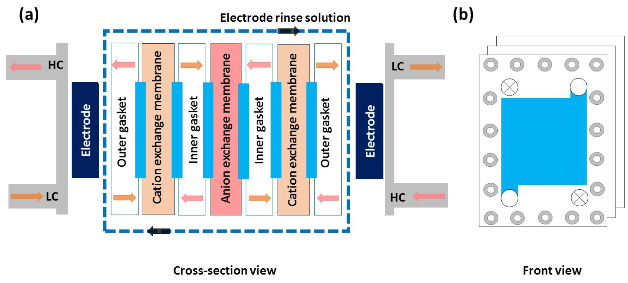
Figure 5: Schematic diagram of different layers in the reverse electrodialysis setup. (a) Cross-section view of a schematic illustration of reverse electrodialysis shows the flow direction of the high-concentration solution, low-concentration solution, and electrode rinse solution. Other components such as electrodes, outer and inner gaskets, outer and inner spacers, cation-exchange membrane, and anion-exchange membrane. (b) Front view of the stack, which shows the flow direction of a solution. Please click here to view a larger version of this figure.
4. Measurement of reverse electrodialysis
- Power calculation
- Let the high concentration, low concentration, and rinse solution, run through the stack at least for 5 min. Measure the RED output performance by a source meter, which is connected to both electrodes of the RED stack13.
- Calculate the RED stack's current-voltage characteristics in terms of power density using the galvanostat method.
NOTE: In the galvanostat method, a constant current is applied across electrodes and measures the resulting current. The resulting current is the current generated due to the electrochemical reaction in the stack. The measurement is carried out under 0.05 V static voltage with a fixed sweep current that is 10 mA. - The maximum power density for the RED stack is measured with the help of the following equation 1.
 (1)
(1)
Here, Pmax is the maximum power density of the RED stack (Wm-2), Ustack is the voltage (V) produced by the membrane in the stack, Istack is the recorded current (A), and Amem is the active area of the membranes (m2).
Results
Net power output
RED cell generally generates electrical energy from the salinity gradient of the salt solution, i.e., ions' movement in the opposite direction through the membrane. To assemble the RED stack correctly, one needs to align all the layers, including electrodes, gaskets, membranes, and spacers in the stack carefully, as demonstrated in the schematic diagram in Figure 4 and Figure 5. If the stack is not perfectly aligned, t...
Discussion
The RED's working principle is mainly dominated by the membrane's physicochemical properties, which is a crucial part of the RED system, as illustrated in Figure 3. Here, we describe the fundamental characteristics of the membrane for delivering a high-performance RED system. Membrane's specific ion permeability makes it pass one type of ions through their polymer nanochannel. As the name suggests, CEM can pass cation from one side to another and restricts anion, whereas AEM can ...
Disclosures
The authors declare no conflicts of interest.
Acknowledgements
This work was supported by the National Research Foundation of Korea (NRF) grant funded by the Korea government (MEST) (No. NRF-2017R1A2A2A05001329). The authors of the manuscript are grateful to the Sogang University, Seoul, Republic of Korea.
Materials
| Name | Company | Catalog Number | Comments |
| AEM based membrane | Fumion | P1810-194 | Ionomer |
| CEM based membrane | Fumion | E550 | Ionomer |
| Digital torque wrench | Torqueworld | WP2-030-09000251 | wrench |
| Labview software | Natiaonal Instrument | - | Software |
| Laptop | LG | - | PC |
| Magnetic stirrer | Lab Companion | - | MS-17BB |
| N, N-Dimethylacetamide | Sigma aldrich | 271012 | Chemical |
| N-Methyl-2- pyrrolidone | Daejung | 872-50-4 | Chemical |
| Peristaltic pump | EMS tech Inc | - | EMP 2000W |
| Potassium hexacyanoferrate(II) trihydrate | Sigma aldrich | P3289 | Chemical |
| Potassium hexacyanoferrate(III) | Sigma aldrich | 244023 | Chemical |
| Pressure Gauge | Swagelok | - | Guage |
| Reverse electrodialysis setup | fabricated in lab | - | Device |
| RO system pure water | KOTITI | - | Water |
| Rotary evaporator | Hitachi | YEFO-KTPM | Induction motor |
| Sodium Chloride | Sigma aldrich | S9888 | Chemical |
| Sodium Hydroxide | Merk | 1310-73-2 | Chemical |
| Source meter | Keithley | - | 2410 |
| Spacer | Nitex, SEFAR | 06-250/34 | Spacer |
| Sulfuric acid | Daejung | 7664-93-9 | Chemical |
| Tube | Masterflex tube | 96410-25 | Rubber tube |
References
- Dlugolecki, P., Gambier, A., Nijmeijer, K., Wessling, M. Practical potential of reverse electrodialysis as process for sustainable energy generation. Environmental Science & Technology. 43, 6888-6894 (2009).
- Kim, D., Kwon, K., Kim, D. H., Li, L. . Energy Generation Using Reverse Electrodialysis: Principles, Implementation, and Applications. , (2019).
- Mei, Y., Tang, C. Y. Recent developments and future perspectives of reverse electrodialysis technology: A review. Desalination. 425, 156-174 (2018).
- Yip, N. Y., Brogioli, D., Hamelers, H. V. M., Nijmeijer, K. Salinity gradients for sustainable energy: primer, progress, and prospects. Environmental Science & Technology. 50, 12072-12094 (2016).
- Li, W., et al. A novel hybrid process of reverse electrodialysis and reverse osmosis for low energy seawater desalination and brine management. Applied Energy. 104, 592-602 (2013).
- Brauns, E. Salinity gradient power by reverse electrodialysis: effect of model parameters on electrical power output. Desalination. 237, 378-391 (2009).
- Cusick, R. D., Kim, Y., Logan, B. E. Energy capture from thermolytic solutions in microbial reverse-electrodialysis cells. Science. 335, 1474-1477 (2012).
- Kim, D. H., Park, B. H., Kwon, K., Li, L., Kim, D. Modeling of power generation with thermolytic reverse electrodialysis for low-grade waste heat recovery. Applied Energy. 189, 201-210 (2017).
- Hong, J. G., et al. Potential ion exchange membranes and system performance in reverse electrodialysis for power generation: A review. Journal of Membrane Science. 486, 71-88 (2015).
- Choi, S. -. Y., et al. Controlling fuel crossover in open electrochemical cells by tuning the water nanochannel for power generation. ACS Sustainable Chemistry & Engineering. 8, 8613-8623 (2020).
- Shah, S. A., et al. Modified single-wall carbon nanotube for reducing fouling in perfluorinated membrane-based reverse electrodialysis. International Journal of Hydrogen Energy. 45, 30703-30719 (2020).
- Kwon, K., Han, J., Park, B. H., Shin, Y., Kim, D. Brine recovery using reverse electrodialysis in membrane-based desalination processes. Desalination. 362, 1-10 (2015).
- Kwon, K., Park, B. H., Kim, D. H., Kim, D. Parametric study of reverse electrodialysis using ammonium bicarbonate solution for low-grade waste heat recovery. Energy Conversion and Management. 103, 104-110 (2015).
- Hatzell, M. C., Ivanov, I., Cusick, R. D., Zhu, X., Logan, B. E. Comparison of hydrogen production and electrical power generation for energy capture in closed-loop ammonium bicarbonate reverse electrodialysis systems. Physical Chemistry Chemical Physics. 16, 1632-1638 (2014).
- Zhu, X. P., He, W. H., Logan, B. E. Reducing pumping energy by using different flow rates of high and low concentration solutions in reverse electrodialysis cells. Journal of Membrane Science. 486, 215-221 (2015).
- Vermaas, D. A., Saakes, M., Nijmeijer, K. Doubled power density from salinity gradients at reduced intermembrane distance. Environmental Science & Technology. 45, 7089-7095 (2011).
- Veerman, J., Saakes, M., Metz, S. J., Harmsen, G. J. Reverse electrodialysis: Performance of a stack with 50 cells on the mixing of sea and river water. Journal of Membrane Science. 327, 136-144 (2009).
- Veerman, J., Saakes, M., Metz, S. J., Harmsen, G. J. Electrical power from sea and river water by reverse electrodialysis: a first step from the laboratory to a real power plant. Environmental Science & Technology. 44, 9207-9212 (2010).
- Batchelor, C. K., Batchelor, G. K. . An Introduction to Fluid Dynamics. , (2000).
- Schock, G., Miquel, A. Mass transfer and pressure loss in spiral wound modules. Desalination. 64, 339-352 (1987).
- Da Costa, A. R., Fane, A. G., Wiley, D. E. Spacer characterization and pressure drop modelling in spacer-filled channels for ultrafiltration. Journal of Membrane Science. 87, 79-98 (1994).
- Vermaas, D. A., Veerman, J., Saakes, M., Nijmeijer, K. Influence of multivalent ions on renewable energy generation in reverse electrodialysis. Energy & Environmental Science. 7, 1434-1445 (2014).
- Vermaas, D. A., Saakes, M., Nijmeijer, K. Enhanced mixing in the diffusive boundary layer for energy generation in reverse electrodialysis. Journal of Membrane Science. 453, 312-319 (2014).
- Moreno, J., Grasman, S., van Engelen, R., Nijmeijer, K. Upscaling reverse electrodialysis. Environmental Science & Technology. 52, 10856-10863 (2018).
- Sarkar, S., SenGupta, A. K., Prakash, P. The donnan membrane principle: opportunities for sustainable engineered processes and materials. Environmental Science & Technology. 44, 1161-1166 (2010).
- Kim, H. -. K., et al. High power density of reverse electrodialysis with pore-filling ion exchange membranes and a high-open-area spacer. Journal of Materials Chemistry A. 3, 16302-16306 (2015).
- Długołęcki, P., Nymeijer, K., Metz, S., Wessling, M. Current status of ion exchange membranes for power generation from salinity gradients. Journal of Membrane Science. 319, 214-222 (2008).
- Geise, G. M., Curtis, A. J., Hatzell, M. C., Hickner, M. A., Logan, B. E. Salt concentration differences alter membrane resistance in reverse electrodialysis stacks. Environmental Science & Technology Letters. 1, 36-39 (2014).
Reprints and Permissions
Request permission to reuse the text or figures of this JoVE article
Request PermissionExplore More Articles
This article has been published
Video Coming Soon
Copyright © 2025 MyJoVE Corporation. All rights reserved