Method Article
Design and Building of a Customizable, Single-Objective, Light-Sheet Fluorescence Microscope for the Visualization of Cytoskeleton Networks
In This Article
Summary
This protocol describes in detail how to build a single-objective, light-sheet fluorescence microscope and its usage for visualizing cytoskeleton networks.
Abstract
Reconstituted cytoskeleton composites have emerged as a valuable model system for studying non-equilibrium soft matter. The faithful capture of the dynamics of these 3D, dense networks calls for optical sectioning, which is often associated with fluorescence confocal microscopes. However, recent developments in light-sheet fluorescence microscopy (LSFM) have established it as a cost-effective and, at times, superior alternative. To make LSFM accessible to cytoskeleton researchers less familiar with optics, we present a step-by-step beginner's guide to building a versatile light-sheet fluorescence microscope from off-the-shelf components. To enable sample mounting with traditional slide samples, this LSFM follows the single-objective light-sheet (SOLS) design, which utilizes a single objective for both the excitation and emission collection. We describe the function of each component of the SOLS in sufficient detail to allow readers to modify the instrumentation and design it to fit their specific needs. Finally, we demonstrate the use of this custom SOLS instrument by visualizing asters in kinesin-driven microtubule networks.
Introduction
Light-sheet fluorescence microscopy (LSFM) represents a family of high-resolution fluorescence imaging techniques in which the excitation light is shaped into a sheet1,2, including selective plane illumination microscopy (SPIM), swept confocally-aligned planar excitation (SCAPE), and oblique-plane microscopy (OPM)3,4,5,6,7. Unlike other microscopy modalities such as epi-fluorescence, total internal reflection fluorescence microscopy (TIRFM), or confocal microscopy, phototoxicity is minimal in LSFM and samples can be imaged over longer timescales because only the plane of the sample being actively imaged is illuminated8,9,10. Therefore, LSFM techniques are extremely useful for imaging 3D samples over extended time periods, notably even those too thick for confocal microscopy techniques. Due to these reasons, since its original development in 2004, LSFM has become the imaging technique of choice for many physiologists, developmental biologists, and neuroscientists for the visualization of entire organisms such as live zebrafish and Drosophila embryos3,4,6,11. In these last two decades, the advantages of LSFM have been leveraged to visualize structure and dynamics at progressively smaller scales, including the tissue11,12, cellular, and subcellular scales, both in vivo and in vitro13,14,15,17.
Despite the reports of successful use cases in the literature, the high cost of commercial LSFM systems (~0.25 million USD as of the time of writing)18,19 prevents the widespread use of the technique. To make DIY builds a feasible alternative for researchers, multiple build guides have been published8,13,20,21, including the open-access effort OpenSPIM22. However, to date, researchers with minimal optics experience can only use earlier LSFM designs, which are incompatible with traditional slide-mounted samples (Figure 1A). Recent single-objective, light-sheet (SOLS) implementation use a single objective for both the excitation and detection (Figure 1C), thereby overcoming the limitation related to compatibility5,6,8,13,20. However, the cost for the versatility of the SOLS design is a substantial increase in the complexity of the build due to the requirement of two additional objectives to relay, de-tilt, and reimage the object plane onto the camera for imaging (Figure 1D). To facilitate access to the complex SOLS-style setups, this paper presents step-by-step guide on the design, build, alignment process, and use of a slide-compatible SOLS system, which would be useful to researchers with knowledge of only an entry-level optics course.
Although the protocol itself is succinct, readers must refer to other resources during the preparation steps to learn more about particular parts of the design or hardware considerations. However, if a reader intends to follow the specifications of this design, it may not be necessary to understand how to select particular optical components.
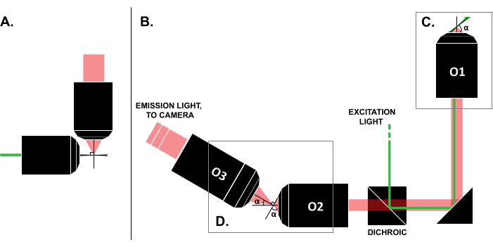
Figure 1: Characteristics of different LSFM configurations. (A) The setup with two orthogonal objectives common in early LSFM designs. In this configuration, a capillary tube or a cylinder of gel is used to contain the sample, which is not compatible with traditional slide mounting techniques. (B) A schematic of an SOLS light-sheet design showing the following: (C) the single objective used for both the excitation and emission collection at the sample plane (O1); this allows a traditional slide to be mounted on top, and (D) the relay objective system in the SOLS emission path. O2 collects the emission light and demagnifies the image. O3 images the plane at the correct tilt angle onto the camera sensor. Abbreviations: LSFM = light-sheet fluorescence microscopy; SOLS = single-objective light-sheet; O1-O3 = objectives. Please click here to view a larger version of this figure.
Protocol
1. Preparation for alignment
- Before starting the build, perform any necessary literature reviews to have a clear idea of the intended use case (e.g., the fluorophores to be imaged, the necessary imaging volume, the resolution requirements). In particular, refer to the representative results section below to decide whether following the exact design described here is appropriate. If it is, skip to step 1.2. If not, find suggestions and guidance for hardware selection at the Sheunglab SOLS Build Guide23.
NOTE: The user can find more information regarding the specifications of this particular system in the discussion section. - Collect all of the necessary optical, opto-mechanical, and electrical components as detailed in the Table of Materials. For users modifying the system, collect all the equivalent parts.
- Build the alignment laser as depicted in Figure 2A. Check that the beam is collimated using the shear plate.
- Build the double frosted glass disk alignment cage as depicted in Figure 2B.
- Prepare the fluorescent dye-coated test sample.
- Create a saturated rhodamine dye solution by gradually adding 1 mL of distilled water to 0.2 g of lyophilized powder until it is all dissolved. Vortex to homogenize.
NOTE: This solution is light-sensitive. Although there are no necessary precautions during preparation, ensure that the solution is stored in a dark area after it has been prepared.
CAUTION: Always wear gloves and a mask when handling rhodamine powder. - Pipette 10 µL onto the center of a test slide.
- Place a 22 mm x 22 mm cover glass on top of the liquid, ensuring that the layer of fluorescence is as thin as possible.
- Seal with clear nail polish.
NOTE: This sample is light-sensitive. To maximize the sample's lifetime, ensure that the slide is stored in a dark area when it is not in use.
- Create a saturated rhodamine dye solution by gradually adding 1 mL of distilled water to 0.2 g of lyophilized powder until it is all dissolved. Vortex to homogenize.
- Prepare the 3D bead sample (1 µm beads embedded in gel).
- Use double-sided tape to create a 4-5 mm wide vertical channel on a sample slide three layers of tape high.
- Place a 22 mm x 22 mm cover glass on top of the tape in the center of the slide. Press firmly on the taped regions to ensure a good seal between the tape and the cover glass.
- Use a razor blade to remove the excess tape.
- Prepare 125 mL of saturated gellan gum solution by gradually adding DI water to 1 g of gellan gum powder. This solution will be solid at room temperature and liquid at 65 °C.
- Introduce 1 mL of gellan gum solution into a microcentrifuge tube. Heat a container of water on a hot plate at 65 °C, and warm the microcentrifuge tube until the gellan gum is visibly viscous.
- Prepare 10 µL of a 1:1,000 dilution of beads in warmed gellan gum solution.
- Carefully pipette the solution into the chamber until full. Use a toothpick to dab a small amount of epoxy on both sides of the channel, fully covering the openings to seal. To ensure proper sealing, visually inspect both ends to make sure that the epoxy has slightly penetrated each end of the channel.
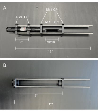
Figure 2: Photos of the alignment tools. (A) Collimated alignment laser. AL1: Alignment Lens 1, −50 mm; AL2: Alignment Lens 2, 100 mm (B) Double frosted glass disk alignment cage. Abbreviations: RMS CP = RMS threaded cage plate; SM1 CP = SM1 threaded cage plate. Please click here to view a larger version of this figure.
2. Aligning the excitation path
- Sketch out the microscope layout on the surface of the optical table. Measure all the distances as accurately as possible.
NOTE: Refer to Figure 3 for the location of the components within the system. - Mount the excitation laser onto the table. Set two irises to the intended height of the laser, and mount them 2-3 ft apart on the desired line of holes behind the location of Mirror 1 (M1). Use these irises to ensure that the beam is level with the table surface and centered on the line of holes on the optical table.
NOTE: Wear laser safety glasses for eye protection, and block off any stray laser beams with laser safety screens as a safety precaution. Until all the components are permanently clamped down, drift on the order of hours is possible. Set up an iris at the furthest point of the alignment at the end of each day as a quick visual check for drift when returning to the build. Vibrations, an improperly floated optical table, and air currents are the most common causes of optical drift. - Mount the laser shutter as close as possible to the excitation laser. Utilize this shutter to quickly block the laser light during alignment, rather than repeatedly turning the laser on and off.
- Assemble the ND filters into the ND filter wheel (ND 0.5, 1.0. 2.0, 3.0, 4.0, and a blank slot), and mount after the laser shutter.
- Switch the motorized actuator onto one translation stage (TS1), and then insert the stage under the location of M1. Ensure that the stage translates axially along the same line of holes that the laser light follows. Set the stage in the middle of its range for the initial placement.
- In the following steps 2.6-2.10, insert the reflective optical components into the beam path one at a time to direct the laser along the path as drawn on the table. Use the pair of irises set to the exact height to define the desired exit beam path and guide the placement and alignment of each reflective element. For each element, adjust the height and position of the mount to ensure that the incoming beam hits the center. Then, rotate the base of the mount to direct the beam along the drawn-out beam path on the table so that it passes through both irises, and fine-adjust the tilt of the outgoing beam with the knobs on the back of each mount.
NOTE: After each element is aligned to the correct height, add a slip-on collar to the post to secure the height.
- In the following steps 2.6-2.10, insert the reflective optical components into the beam path one at a time to direct the laser along the path as drawn on the table. Use the pair of irises set to the exact height to define the desired exit beam path and guide the placement and alignment of each reflective element. For each element, adjust the height and position of the mount to ensure that the incoming beam hits the center. Then, rotate the base of the mount to direct the beam along the drawn-out beam path on the table so that it passes through both irises, and fine-adjust the tilt of the outgoing beam with the knobs on the back of each mount.
- Mount and align M1 on top of TS1.
- Mount and align the dichroic onto the table.
- Following the manufacturer's instructions, connect the galvo to the power supply and function generator.
- Mount the galvo such that the laser is incident on the exact center of the mirror. Power on the galvo, and then press and hold the AM button on the waveform generator to set the mirror tilt to 0 V DC current (center of the range). Now, align the galvo to the irises.
- Mount and align Mirror 2 (M2).
- Insert the large cylindrical mirror into the cylindrical mirror mount. Use 1 in cage rods to attach a 30-60 mm cage adapter above Mirror 3 (M3). Use the knobs on the mirror mount to flatten the tilt of the M3 mirror for the initial placement.
- Mount the double-frosted glass alignment cage into the cage adapter above M3; be sure to tighten the set screws on the cage adapter that hold the alignment cage in place each time it is used for alignment. Mount M3 to the table, and adjust the height and position until the beam is roughly centered on both frosted glass alignment disks. Clamp M3 to the table, and use a post mount, 3 in post, 90° clamp, and 2 in post on both sides of M3 to add support using the taped holes on either side of the mirror mount. Use the knobs on the back of the mirror to fine-adjust the beam.
NOTE: All the reflective elements in the excitation path are now set and should not be touched. - Mount Lens 1 (L1) onto the table. For all the initial lens placements, use a screw-on lens target to center the incoming beam on the front of the lens. Adjust the tilt and lateral position of Lens 1 (L1) until the beam is centered on both of the frosted glass plates on the alignment cage above M3.
- Mount Lens 2 (L2) in its respective position to create a 4f system with L1. Move L2 axially to obtain a collimated beam, and use the excitation laser and the shear plate to check the collimation. Adjust the tilt and lateral position of L2 to center the beam on both the frosted glass disks above M3.
- Mount the pinhole into an xy translation mount. Mount this on top of a 1D translation stage to provide fine axial translation. Mount the pinhole and stage onto a post and post mount, and place it at the shared focal point in between L1 and L2. Adjust the pinhole by hand until the laser light can be seen through the pinhole.
- Mount the power meter sensor immediately after the pinhole, and use the wavelength button on the digital console of the power meter to select the wavelength of the excitation laser. Adjust the xy position of the pinhole to maximize the transmission and obtain a near TEM00 beam profile. Then, adjust the pinhole axially with the 1D stage to further maximize the transmission.
- Mount Lens 4 (L4) onto the table in its position, and adjust the mount to the correct height. Adjust L4 axially so that the excitation beam is focused on the surface of the galvo. Adjust the tilt and lateral position of L4 to center the beam on both the frosted glass disks above M3.
- Mount Lens 3 (L3) onto the table in its position, and adjust the mount to the correct height. Use the excitation laser and the shear plate to check the collimation of L3 and L4. Adjust the tilt and lateral position of L3 to center the beam on both the frosted glass disks above M3.
- Temporarily remove L3. Mount Scan Lens 1 (SL1) onto the table, and adjust the axial distance to form a collimated telescope with L4, as measured with the shear plate. Adjust the tilt and lateral position of SL1 to center the beam on both the frosted glass disks above M3.
- Reinsert L3. Mount Tube Lens 1 (TL1), and use the excitation beam and shear plate to collimate SL1 and TL1. Adjust the tilt and lateral position of TL1 to center the beam on both the frosted glass disks above M3.
- Using an adapter ring, screw Objective 1 (O1) into the cage plate above M3. Remove SL1 temporarily, and let the beam hit the ceiling. Adjust the height (axial distance) of O1 on the cage system until the beam forms an Airy disk on the ceiling, and then continue adjusting until the size of the disk is minimized.
- With O1 in place, mount the sample stage in the appropriate position.
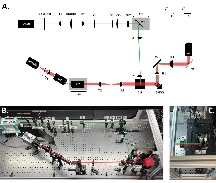
Figure 3: Location of the components within the SOLS system. (A) Schematic layout of the SOLS system with all the components labeled. (B) Top-down photo of the physical SOLS system on the optical table, excluding the sample stage area. (C) Top-down photo of the sample stage area (extension to Figure 3B). The excitation path is shown in green. The emission path is shown in red. Focal lengths of the lenses: L1: 100 mm; L2: 45 mm; CL1: 50 mm; CL2: 200 mm; CL3: 100 mm; L3:150 mm; L4: 100 mm; SL1: 75 mm; TL1: 200 mm; SL2: 150 mm; TL2: 125 mm; TL3: 200 mm. See the Table of Materials for more detailed part specifications. Abbreviations: SOLS = single-objective light-sheet; ND Wheel = variable neutral density filter wheel; L1-L4 = plano concave achromat lenses; CL1-CL3 = cylindrical lenses; M1-M3 = mirrors; TS1-TS2 = translation stages; DM = dichroic mirror; Galvo = scanning galvanometer; SL1-SL2 = scan lenses; TL1-TL2 = tube lenses; O1-O3 = objectives; EF = emission filter. Please click here to view a larger version of this figure.
3. Aligning the emission path
- Set up the alignment laser.
- Mount two empty cage plates beside the excitation laser at the same height as the laser. Use these cage plates to mount the alignment laser by sliding the cage rods of the alignment laser into the empty holes in the two cage plates. Ensure that the laser can be set to the on position, either by taping around the power button or by wiring an on/off switch.
- Remove O1, and reinsert the frosted glass alignment cage. Use one kinematic mirror mount and one drop-down mirror to align the alignment beam to the excitation beam path.
- Use the power meter to maximize the signal of the alignment beam after the pinhole by fine-adjusting the two mirrors. Ensure that the beam remains centered on the frosted glass alignment cage.
- Remove the alignment cage, and reinsert O1. Place the square mirror on the sample stage of O1, and adjust the mirror axially until the size of the beam profile is minimized after the dichroic.
- Mount one iris in the emission path and far enough back so that Scan Lens 2 (SL2), Tube Lens 2 (TL2), and Objective 2 (O2) can be inserted without interference. Align this iris to the alignment laser. Mount a frosted glass disk at least 1 in behind the iris, and ensure this is also aligned to the laser light.
- Insert SL2 at the correct distance, as measured from the galvo with a ruler. Adjust the tilt and lateral position of SL2 so that the incoming alignment beam is centered on SL2 and the outgoing beam passes through the iris and frosted glass disk.
- Insert TL2 at the correct distance, as measured from SL2 with a ruler. Adjust the tilt and lateral position of TL2 so that the incoming alignment beam is centered on TL2 and the outgoing beam passes through the iris and frosted glass disk.
- Mount TS2 onto the table. Ensure that the stage translates along the optical axis of O2.
- Screw O2 onto an xy translation mount. Connect a post under the xy mount to mount O2 onto the translation stage. Use a screw-on target to center the back of O2 on the red laser.
- Adjust the xy knobs and tilt of O2 so that the red alignment beam passes through the iris and frosted glass disk.
- Move the alignment laser to above O1 and directed downward into the emission path. Turn on the laser, and ensure that this beam is centered on all the lenses in the emission path.
- Conjugate the pupil planes of O1 and O2 by opening the iris and removing the frosted glass disk so that the alignment beam exiting O2 continues unobstructed to a faraway surface or wall (>0.5 m) (Figure 4). Adjust TS2 until the beam forms a small Airy disk on the surface, and then continue adjusting TS2 to minimize the size of the Airy disk.
NOTE: A strongly diverging beam indicates the incorrect placement of O2. However, because this beam passes through two objectives, a small amount of divergence is inherent. As such, the Airy disk is the best guide. - Optimize the galvo for tilt-invariant scanning: Press the FSK button on the waveform generator to select a triangle wave signal for the galvo, and set to a low frequency (~1 Hz). Observe the alignment beam on the same faraway surface or wall.
NOTE: If the galvo is placed incorrectly, the beam will sweep horizontally on the surface along with the galvo movement. This can be resolved through fine adjustments (by hand) of the tilt and xy position of the galvo base until the beam displacement is undetectable by eye. - Check the quality of the system by imaging at 0°.
- Screw O3 into an xy translation mount. Screw a 1 in lens tube into the cage translation stage, and screw the xy translation stage into the tube. Use two cage rods to connect the front of the cage translation stage to a cage plate, and mount the cage plate to a post. Mount Objective 3 (O3) close to the front of O2 (~4-5 mm) at 0°, and adjust the height to match.
- Mount a frosted glass alignment disk in the shared focal plane between SL2 and TL2, as measured with a ruler. Mount the acrylic fluorescent test slide onto the stage, and illuminate the slide with the excitation laser. Look through the back of O3, adjust both the height and axial position of O3 to find the emission light, and then adjust O3 axially until the emission light fills the back aperture (Figure 5).
- Screw two 8 in cage rods into the back of the O3 translation stage. Slide a cage plate with a mounted frosted glass disk onto the rods, and then fine-adjust O3 using the xy mount to ensure that the emission light exits O3 centered. Then, remove the cage rods.
- Mount a frosted glass disk in the rough position of the camera sensor, and align the height and position of the disk to the emission light.
- Screw Tube Lens 3 (TL3) into a cage plate, and mount it immediately behind O3. Center TL3 on the incoming emission light, and then adjust the tilt of TL3 to align the outgoing light to the frosted glass disk.
- Mount the camera at the correct distance from the tube lens, as measured with a ruler.
- Screw both 2 in lens tubes and the emission filter onto the camera.
- Remount the frosted glass alignment disk in the shared focal plane between SL2 and TL2. Mount the fluorescent dye test sample, and illuminate the sample with the excitation beam.
- Turn on the camera, and then open the Micromanager program on the connected computer. Click on Live to enter live view. Click on Auto Once to set the initial exposure settings, and then reset the exposure as necessary when imaging.
NOTE: Micromanager will not function properly unless it is opened after the camera has been turned on. - Adjust the xy translation knobs on the O3 mount until the small hole in the glass alignment disk is centered within the field of view (FoV). Adjust O3 axially with the cage translation stage until the hole is in focus; the edges should appear sharp (Figure 6).
- Image fluorescent beads to check the quality of the system.
- Remove the frosted glass alignment disk, mount the 3D bead sample, and illuminate the sample with the excitation beam.
- Adjust the height of the sample relative to O1 until the fluorescent beads fill a circular region in the center of the FoV.
- Fine-adjust the position of O3 using the xy stage and the axial translation stage until the point spread functions (PSFs) are round (indicative of minimal aberrations) and bright (indicative of a good signal-to-noise ratio) (Figure 7). If this cannot be achieved by adjusting O3, it is highly likely that the optical system in between components O1 and O2 is sub-optimally aligned; follow the diagnostic checks in step 3.13 below.
- If round PSFs can be obtained, skip the diagnostic step, and move on to tilting the imaging system.
- Perform diagnostic checks if needed.
NOTE: Once good PSFs are obtained, the rest of the diagnostic steps can be skipped.- Mount the brightfield (BF) light above O1. Mount the positive grid test target on the sample stage at the same axial height as the alignment mirror. Center the 10 µm grid, and illuminate the grid with the BF light.
- Image the grid on the camera, and translate the sample until the grid is in focus. Use the grid image to confirm that the field across the FoV is flat: if not, the grid will appear distorted and bowed. To correct for a bad grid image, adjust the xyz position and tilt of O3, and then adjust the TL3 and the camera accordingly.
NOTE: If a flat grid can be achieved, repeat step 3.12.10, and then move on to tilting the imaging system. - Set up the alignment camera or the imaging camera at the correct distance so that SL2 focuses the image onto the sensor. Image the grid target at the intermediate plane (Figure 8). If this grid is also skewed, it is highly likely that the optical system in between components O1 and SL2 is sub-optimally aligned and should be revisited. Optimize the alignment as necessary before progressing.
NOTE: If the camera does not fit in between SL2 and TL2, use an extra mirror to bounce the image 90° after SL2 and onto the camera. - Check the PSFs at the intermediate plane: After checking the grid, another good diagnostic check is to check the PSFs at the same intermediate plane. A good image at this plane, which is similar to Figure 7 but at a different magnification (Figure 9), indicates good alignment through SL2.
NOTE: If a flat grid and round PSFs can be achieved at the intermediate plane, repeat step 3.13.2, then step 3.12.10, and then move on to tilting the imaging system.
- Tilt the O3 imaging sub-system to 30°.
- Remove O3, TL3, and the camera.
- Reinsert O3 at 30° to the optical axis of O2 using the lines on the table as a guide.
- Mount a frosted glass alignment disk in the shared focal plane between SL2 and TL2. Mount the acrylic fluorescent test slide onto the stage, and illuminate the slide with the excitation laser. Once again, look through the back of O3, adjust both the height and axial position of O3 to find the emission light at 30°, and then adjust O3 axially until the emission light fills the back aperture.
- Remove the frosted glass alignment disk from in between SL2 and TL2 to obtain a stronger emission signal.
- Screw two 8 in cage rods into the back of the O3 translation stage. Slide a cage plate with a mounted frosted glass disk onto the rods, and then fine-adjust O3 using the xy mount to ensure that the emission light exits O3 centered. Then, remove the cage rods.
- Mount a frosted glass disk in the rough position of the camera sensor, and align the height and position of the disk to the emission light.
- Mount TL3 immediately behind O3. Center TL3 on the incoming emission light, and then adjust the tilt of TL3 to align the outgoing light to the frosted glass disk.
- To more accurately set the TL3-camera distance, carefully unscrew O3, and mount the alignment laser so that it is focused by TL3 onto the camera. Use ND filters as necessary so that the laser intensity is <1 mW. Start the camera live view, and adjust TL3 axially to minimize the laser spot on the camera.
- Remount the frosted glass alignment disk in the shared focal plane between SL2 and TL2. Mount the fluorescent dye test sample, and illuminate the sample with the excitation beam. Adjust the xy translation knobs on the O3 mount until the small hole in the glass alignment disk is within the FoV on the camera. Adjust the cage translation stage to move O3 axially until the hole is in focus; ensure that the hole appears similar to how it did at 0°.
- Remount the positive grid test target at the same axial height, and illuminate the grid with the BF light. Confirm that only one vertical section is in focus (due to the 30° tilt). Once again, use the grid image to confirm that the field across the FoV is flat, even when out of focus. When the slide is translated axially, confirm that the in-focus portion of the FoV (grid target) sweeps across the screen horizontally, while the grid squares maintain a consistent size (Figure 10).
NOTE: Due to the tilt of the imaging plane at the sample, the grid may appear slightly stretched in the x-plane.
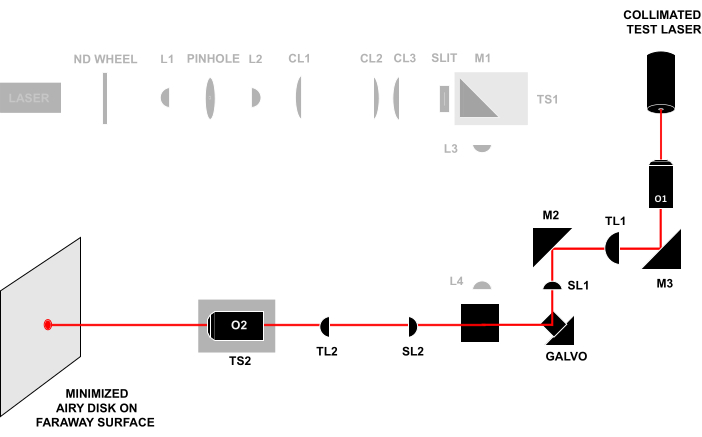
Figure 4: Laser-in-laser-out technique. Sending a collimated test beam through the front of O1 and observing the beam that exits O2 on a faraway surface. If all the components are aligned at the correct distance, the beam will form a small Airy disk on the faraway surface. All abbreviations are the same as in Figure 3. Please click here to view a larger version of this figure.
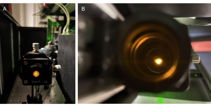
Figure 5: Utilizing emission light for alignment. (A) Emission light from an acrylic fluorescent slide on a screw-on target behind the BFP of O2. (B) Finding the emission light by sight through the back of O3. Abbreviations: O2-O3 = objectives; BFP = back focal plane. Please click here to view a larger version of this figure.
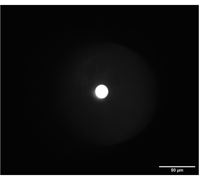
Figure 6: On-camera image of the correctly focused frosted glass alignment disk. The disk was placed at the intermediate plane between SL2 and TL2. Scale bar = 50 µm. Abbreviations: SL2 = scan lens; TL2 = tube lens. Please click here to view a larger version of this figure.
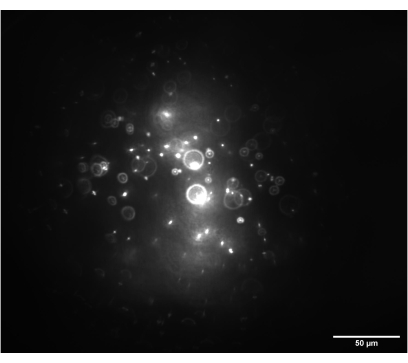
Figure 7: Camera image of the 3D bead sample. The image shows 1 nm beads with the imaging module set to 0° and illuminated by a circular beam prior to the insertion of the cylindrical lenses. Scale bar = 50 µm. Please click here to view a larger version of this figure.
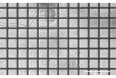
Figure 8: Positive grid test target correctly focused at the intermediate plane between SL2 and TL2. The flat grids throughout the entirety of the field indicate good alignment of the components SL2 and prior. Scale bar = 30 µm. Abbreviations: SL2 = scan lens; TL2 = tube lens. Please click here to view a larger version of this figure.
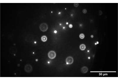
Figure 9: Camera image of the 3D bead sample. The image shows 1 nm beads correctly focused at the intermediate plane between SL2 and TL2. Scale bar = 30 µm. Abbreviations: SL2 = scan lens; TL2 = tube lens. Please click here to view a larger version of this figure.
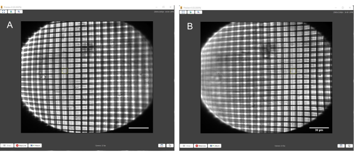
Figure 10: Positive grid test target with a yellow square of consistent size overlaid to match the squares of the grid. (A) Grid in focus on the left-hand side. (B) Grid in focus on the right-hand side. The yellow square matches the size of the grid boxes on both sides of the FoV. Scale bars = 30 µm. Abbreviation = FoV = field of view. Please click here to view a larger version of this figure.
4. Aligning the oblique light sheet
- Remove O1, and re-insert the double frosted glass alignment cage in its place. Confirm that the beam is collimated and centered on both frosted glass disks.
- Screw Cylindrical Lens 1 (CL1) into a rotating lens mount. Mount CL1 into the optical path, and rotate the mount so that the beam is expanded in the direction vertical to the optical table. Adjust the tilt and lateral position of CL1 so that the beam is centered on the front and maintains a centered position on both frosted glass disks.
- Screw Cylindrical Lens 2 (CL2) into a rotating lens mount, and mount CL2 into the optical path at the correct distance to form a 4f system with CL1. Rotate CL2 to the same orientation as CL1 so that the beam is stretched in the direction vertical to the optical table and collimated. Use a test card to measure the height of the cylindrical beam profile at multiple locations to ensure that the beam is collimated. Adjust the tilt and lateral position of CL2, as performed in step 4.2.
- Screw Cylindrical Lens 3 (CL3) into a rotating lens mount, and mount CL3 into the optical path at the correct distance to form a 4f system with L3. Rotate CL3 to the same orientation as both CL1 and CL2 so that the beam is focused down to a horizontal sheet profile at the focal plane. Adjust the tilt and lateral position of CL3, as performed in step 4.2.
- Insert the slit: Using four 4 in cage rods and the CL3 cage mount, mount the slit in a vertical orientation at the focal plane between CL3 and L3, as measured with a ruler. Use the stretched excitation beam profile to adjust the height and lateral position of the slit until it is centered on the beam.
- Reinsert O1, mount the fluorescent dye test sample, and illuminate the sample with the excitation light sheet. At the camera sensor, confirm that the 0° light sheet appears as a thin vertical sheet (Figure 11A).
- Remove the fluorescent dye test sample, and wipe O1 clean. Let the light sheet expand above O1 unobstructed. Using the motorized translation stage control, translate M1 toward the cylindrical lenses to set the angle of the light sheet to roughly 60° relative to the optical axis of O1.
NOTE: It is crucial that the light sheet is tilted in the correct direction to align with the similarly tilted imaging plane (Figure 12); if a system is laid out differently from this specific design, the correct direction of the tilt can be figured out through geometric ray tracing.
NOTE: For reference, translating M1 2.647 mm toward the slit set the light sheet to the correct tilt in this setup. - Reinsert the fluorescent dye test sample to image the tilted sheet. Ensure that the light sheet has maintained a vertical beam shape on the camera but is wider and fainter (Figure 11B) .
- Translate the sample axially with the stage so that the fluorescent dye is illuminated by the light sheet at five different depths between the center of the FoV and the right-hand side of the screen. Save each image.
- Open the images in Fiji. For each image, select the Line tool, and draw a horizontal line from the center of the FoV to the center of the light sheet. To measure the displacement, go to Analyze | Measure to see the length of the lines. Then, plot the displacement of the light sheet as a function of sample depth to calculate the angle of the light sheet above O1.
- Translate M1 slightly. Repeat step 4.9 and step 4.10 until the angle of the light sheet is 60° from the optical axis of O1, matching the angle of the imaging plane.
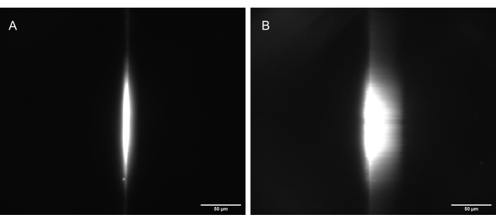
Figure 11: Camera images of the fluorescent dye test sample illuminated by a correctly shaped light sheet. (A) The sheet at 90°, straight up along the optical axis of O1, and (B) tilted to 30° (60° to the optical axis of O1). Scale bars = 50 µm. Abbreviation: O1 = objective. Please click here to view a larger version of this figure.
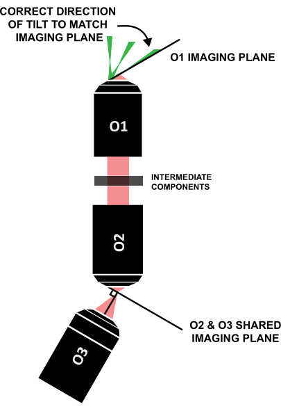
Figure 12: Correct direction of the light-sheet tilt to align with the imaging plane of O1. Abbreviation: O1-O3 = objectives. Please click here to view a larger version of this figure.
5. Fine-tuning the system for imaging and data collection
- Mount the 3D bead slide, and translate the sample axially with the stage until the beads fill the FoV on the camera.
- Adjust O3 using the xy stage and the cage translation stage, aiming to minimize aberrations and optimize the signal-to-noise ratio in the image (Figure 13).
- Adjust the correction collar of O1, aiming to minimize aberrations and optimize the signal-to-noise ratio in the image.
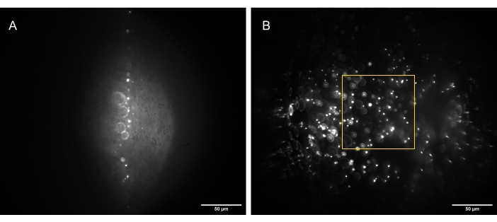
Figure 13: Camera images of the 3D bead sample (1 µm beads) illuminated by a correctly shaped light sheet. (A) Sheet at 90°, straight up along the optical axis of O1, and (B) tilted to 30° to the optical axis of O1. The yellow box indicates the portion of the FoV that is flat, consistent, and usable (80 µm x 80 µm) and in which reliable data can be captured. Scale bars = 50 µm. Abbreviations: O1 = objective; FoV = field of view. Please click here to view a larger version of this figure.
6. Calibrating the magnification of the system
- Mount the positive grid test target on the sample stage, and illuminate with the brightfield light.
- Translate the grid slide axially with the stage to bring the grid slide into focus. Bring the center of the grid into focus.
- Capture and save the image, and then open it in Fiji.
- Use the Line tool and Measure function in Fiji to accurately measure the distance between two grid lines in pixels. Divide this value by the known distance (10 µm), to determine the pixel-to-micron calibration.
- Compute the magnification (M) of the system using the measured size of the pixel and the known size of a pixel with equation (1).
 (1)
(1)
7. Acquiring volumetric scans
- Position the sample.
- Turn on the camera preview, galvo, function generator, power supply, stage, and excitation laser.
- Mount the sample, and then click the FSK button on the function generator to set a triangle wave. To find the sample, use the function generator to set the following: 400 mV peak-to-peak amplitude (using the Ampl. button), 0 offset (using the Offset button), and 200 mHz frequency. Use the Micromanager window to set a 100 ms exposure time.
- Scroll in z manually until the sample plane is reached. Optimize the z setting so that the desired region for the volumetric scan passes through the screen during one cycle.
- Select the scan parameters.
- Ensure that the peak-to-peak amplitude is set correctly by visually checking that the preview looks to be in focus for the duration of the scan. If the image quality degrades sooner approaching one end of the scan than the other, edit the offset on the function generator to move the center of the scan toward the better region.
- In the Micromanager program, select an exposure time, and click on Multi-D Acq. to open the Multi-Dimensional Acquisition window. Use the Count box to choose the number of frames, which will set the total acquisition time. The interval between frames (frame rate) will be set by the exposure time unless a longer interval is specified in the Interval box. On the function generator, set the frequency to create a full volume scan by one half of the period of the triangle wave function (linear scan in one direction).
NOTE: If the frame rate and frequency are too low, too few frames will be acquired for a volume scan, and the low frame number will create visible artifacts in the post-processing. For reference, Figure 13 was composed of ~100 frames in the scan, and Figure 14 was composed from ~800. It is also critical to consider the sample itself when selecting the parameters. Ensure that the exposure time is set so that the sample is sufficiently excited but not saturated. The excitation laser intensity can also be adjusted to this end. If the user is acquiring a series of volumetric scans to characterize a time-varying process in 3D, ensure that the scanning timescale exceeds the timescale dynamics of the system.
- Collecting videos: Acquire a time-lapse that captures at least the duration of a full ramp up or ramp down of the triangle wave, corresponding to one full scan of the volume.
8. Post-processing procedures
- Deskewing volumetric image stacks
- Deskew the volume scans to convert the stack of images in tilted planes to a series of images in real xyz coordinates.
NOTE: There exist many excellent guides on light-sheet image post-processing and open-source software to perform the deskewing of existing volume scans, as well as to perform deskewing and save deskewed images during acquisition24. - To deskew the volume scans, obtain the following two parameters: the real distance between two frames in pixels (d), and the angle between the frame plane and the x-y plane (θ is set by the angle of the oblique light sheet (in this system, 30°). The distance between frames will depend on the imaging optics and the acquisition settings.
- Deskew the volume scans to convert the stack of images in tilted planes to a series of images in real xyz coordinates.
- Finding the d parameter
- Calibrate the distance between frames for every time the system is substantially realigned. Perform this calibration with a stack of images of fluorescent beads, as these are the easiest to use for diagnosing issues.
- Acquire a stack of images, and run the deskewing code using any initial guess for the d parameter. Open the deskewed image stack in ImageJ, and scroll through the stack. If d has been set substantially far from its true value, observe that the beads will appear artificially elongated in x or y, and individual beads will appear to move in the xy plane as the user scrolls through the frames in z (rather than focusing and defocusing from the same central point). Iterate over the d parameter multiple times until these issues are no longer apparent.
- Once the d parameter appears to be reasonably close to the true value, compute maximum intensity projections of the image stack along the x and y directions. Note that beads of a diameter near the diffraction limit may appear elongated in z, but they ideally should not appear conical or be elongated diagonally. Fine-tune the deskewing parameters until these criteria do not substantially improve with new iterations. For reference, the data shown in Figure 13 were deskewed at d = 2.50 pixels, and the data in Figure 14 were deskewed at d = 1.0 pixels.
NOTE: The distance between frames will depend linearly on the scan amplitude, frequency, and frame rate.
Results
We performed volumetric scans of 1 µm beads embedded in gellan gum. Figure 14 shows the maximum intensity projections of the deskewed volumetric scans along the x, y, and z directions.
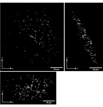
Figure 14: Volumetric imaging of 1 µm fluorescent beads in gellan gum. Maximum intensity projections of deskewed volumetric scans are shown. Scale bars = 30 µm. Please click here to view a larger version of this figure.
We have demonstrated the use of the single-objective, light-sheet microscope to characterize reconstituted cytoskeleton networks by performing volumetric scans of samples of microtubule asters. In brief, rhodamine-labeled, taxol-stabilized microtubules were polymerized from reconstituted dimers by GTP; then, following polymerization, streptavidin-based kinesin motor clusters were mixed into samples along with ATP for final concentrations of 6 µM microtubules, 0.5 µM kinesin dimers, and 10 mM ATP. Extensive protocols and guides for the preparation of taxol-stabilized microtubules and kinesin motor clusters can be found on the Mitchson Lab and Dogic Lab websites25,26. The samples were pipetted gently into microscope slides, sealed, and allowed to sit for 8 h before imaging to allow for motor activity to cease so that the samples reached a steady structural state that resembled asters.
Studies of reconstituted cytoskeleton systems most frequently employ confocal or epifluorescence microscopy to image labeled filaments. However, both of these techniques are limited in their capability to image dense 3D samples27. While much progress has been made in in vitro cytoskeleton-based active matter research by constraining samples to be quasi 2D28,29, cytoskeleton networks are inherently 3D, and many current endeavors lie in understanding the effects that can only arise in 3D samples29,30, thus creating a need for high-resolution 3D imaging.
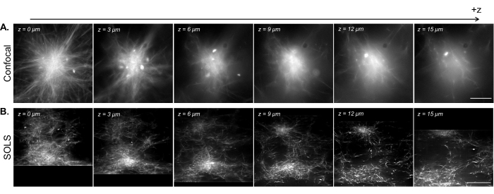
Figure 15: Facilitation of the 3D visualization of reconstituted cytoskeleton samples by single-objective light-sheet microscopy. (A) Images of fluorescent microtubule asters acquired on a Leica DMi8 laser-scanning confocal microscope. The images show different planes from a z-scan. Scale bar = 30 µm. (B) Deconvolved deskewed images from a volumetric scan performed on the single-objective light-sheet setup of the same sample. Scale bar = 30 µm. The deskewed image area here corresponds to the usable FoV (yellow box) demonstrated in Figure 13B. While the confocal excels at imaging single planes near the coverslip, the density of the fluorescent sample introduces complications when imaging at higher planes due to the additional signal from below the imaging plane. The light sheet circumvents this issue by only illuminating the imaging plane, thus allowing for uniformly sharp imaging at different planes in z. Abbreviations: SOLS = single-objective light-sheet; FoV = field of view. Please click here to view a larger version of this figure.
In Figure 15, we demonstrate the volumetric imaging of a reconstituted microtubule network contracted into aster-like structures by kinesin motor clusters. As shown in previous research28,31, these 3D structures tend to grow dense toward the center, resulting in bright regions of fluorescence that are predominant in the signal. In imaging planes near the coverslip (low z level), confocal microscopy (Figure 15A) can resolve single filaments around the periphery of the aster, with additional background toward the center due to out-of-focus fluorescence signals from above. However, moving a few microns in z quickly reduces the quality of the images due to the out-of-focus dense sections of the aster being predominant in the signal in the imaging plane. The single-plane illumination of the light sheet (Figure 15B) eliminates the out-of-focus signals from the dense parts of the aster above and below the imaging plane, thus allowing for comparable image quality between the planes. The light sheet's ability to produce high-quality, reliable volumetric scan data opens up the possibility of visualizing and characterizing 3D phenomena in reconstituted cytoskeleton systems.
Discussion
Two important details regarding this protocol are the overall cost of the system and the expected build and alignment time. Although the exact cost is variable, we can comfortably estimate that the in toto cost of this SOLS or a similar DIY system would fall in the range of $85,000 USD. We note that this estimate considers the retail price of all the components, so this overall price may be greatly reduced by sourcing used components. In terms of the build time, it would be reasonable to expect a user with little optics experience to build and align this entire SOLS system within 1-2 months, provided that all of the components are available and ready. Despite the length and complexity of the protocol, we believe that the amount of detail in the written manuscript, paired with the video protocol, should make this protocol straightforward and fast to follow.
There are two critical steps in this protocol. First, the placement of the galvo determines the placement of many lenses as it is part of three separate 4f lens pairs. It is crucial that the galvo is both conjugated with the back focal planes of O1 and O2 and centered correctly to ensure tilt-invariant scanning. Second, the image quality is extremely sensitive to the alignment of O2 and O3 with respect to each other. Here, care must be taken to ensure that, first, the alignment angle of O3 to O2 matches the tilt of the excitation light sheet, thus providing maximally flat illumination across the similarly tilted FoV. Second, O3 must be placed at the correct axial distance to maintain a flat FoV with as large an area as possible. Third, O3 must be placed at the correct lateral distance from O2 to maximize the signal that passes through the O2-O3 interface.
In terms of the usable FoV, this system achieved a flat, reliable field with consistent illumination across an 80 µm x 80 µm area. This area is smaller than the maximum FoV provided by the camera, so the usable FoV is indicated by the yellow box in Figure 13. In terms of the resolving power, this system achieved a minimum resolvable distance of 432 nm along the x-axis and 421 nm along the y-axis, which was measured by finding the average sigma x and y of Gaussian fits to point spread functions (PSFs) in the good FoV and multiplying by two. We note that this system was not optimized in terms of its total NA, meaning there is room for significant improvement if users desire a resolving power higher than what this system achieved. There are a multitude of compatible objective options for this type of SOLS build, many of which would contribute to a higher system resolution but with the drawbacks of a higher cost, a smaller FoV, or more complicated alignment techniques at the relay interface8,11,13,20. Separately, should users desire a larger FoV, incorporateing a second galvo to allow for 2D scanning would achieve this goal but would require additional optics and control mechanics to be integrated into the design32. We have provided more detail regarding modifications to the system on our website page, alongside links to other helpful resources regarding the design process23.
Beyond improving the specific components for this particular design, it would be very feasible to add other high-resolution microscopy techniques or modalities to this build. One such improvement would be to incorporate multi-wavelength illumination, which would involve aligning additional excitation lasers to the original excitation path8. Furthermore, because this type of SOLS design leaves the sample accessible, adding additional functions to the microscope, including but limited to optical tweezing, microfluidics, and rheometry, is relatively straightforward2,33.
Compared to the myriad light-sheet guides that have been published, this protocol provides instructions at a level of understanding that a user without significant optics experience may find helpful. By making a user-friendly SOLS build with traditional sample slide mounting capabilities accessible to a larger audience, we hope to enable an even further expansion of the applications of SOLS-based research in all fields in which the instrument has or could be utilized. Even with the applications of SOLS instruments rapidly growing in number2,34,35, we believe that many benefits and utilizations of SOLS-type instruments still remain unexplored and express excitement at the possibilities for this type of instrument moving forward.
Disclosures
The authors have nothing to disclose. All research was conducted in the absence of commercial or financial relationships that could be interpreted as a conflict of interest.
Acknowledgements
This work was supported by the National Science Foundation (NSF) RUI Award (DMR-2203791) to J.S. We are grateful for the guidance provided by Dr. Bin Yang and Dr. Manish Kumar during the alignment process. We thank Dr. Jenny Ross and K. Alice Lindsay for the preparation instructions for the kinesin motors.
Materials
| Name | Company | Catalog Number | Comments |
| 1" Plano-Concave Lens f = -50 mm | Thorlabs | LC1715-A-ML | For alignment laser Estimated Cost: $49.5 |
| 1" Achromatic Doublet f = 100 mm (x3) | Thorlabs | AC254-100-A-ML | L2, L4 and alignment laser Estimated Cost: $342.42 |
| 1" Achromatic Doublet f = 125 mm | Thorlabs | AC254-125-A-ML | SL2 Estimated Cost: $114.14 |
| 1" Achromatic Doublet f = 150 mm | Thorlabs | AC254-150-A-ML | L3 Estimated Cost: $114.14 |
| 1" Achromatic Doublet f = 150 mm | Thorlabs | AC254-150-A-ML | TL2 Estimated Cost: $114.14 |
| 1" Achromatic Doublet f = 45 mm | Thorlabs | AC254-045-A-ML | L1 Estimated Cost: $114.14 |
| 1" Achromatic Doublet f = 75 mm | Thorlabs | AC254-075-A-ML | SL1 Estimated Cost: $114.14 |
| 1" Cylindrical Lens f = 100 mm | Thorlabs | LJ1567RM | CL3 Estimated Cost: $117.62 |
| 1" Cylindrical Lens f = 200 mm | Thorlabs | LJ1653RM | CL2 Estimated Cost: $111.22 |
| 1" Cylindrical Lens f = 50 mm | Thorlabs | LJ1695RM | CL1 Estimated Cost: $117.62 |
| 1" Mounted Pinhole, 30 µm Pinhole Diameter | Thorlabs | P30K | Estimated Cost: $77.08 |
| 1" Silver Mirror (x3) | Thorlabs | PF10-03-P01 | M1, M2, one for alignment Estimated Cost: $168.78 |
| 2" Elliptical Mirror | Thorlabs | PFE20-P01 | M3 Estimated Cost: $179.98 |
| 2" Post Holder (x11) | Thorlabs | PH2 | For custom laser mount, ND wheel, safety screens Estimated Cost: $98.45 |
| 2" Posts (x47) | Thorlabs | TR2 | For custom laser mount and optical components Estimated Cost: $277.3 |
| 3" Posts (x4) | Thorlabs | TR3 | For M3 supports and other mounts Estimated Cost: $24.6 |
| 3" Post Holder (x4) | Thorlabs | PH3 | Estimated Cost: $38.48 |
| 30 to 60 mm Cage Adapter | Thorlabs | LCP33 | To mount O1 Estimated Cost: $45.42 |
| 30mm Cage Filter Wheel | Thorlabs | CFW6 | To mount ND filters Estimated Cost: $172.36 |
| 30mm Cage Plate (x6) | Thorlabs | CP33 | To build alignment cage and alignment laser Estimated Cost: $114.54 |
| 30mm Right-Angle Kinematic Mirror Mount (x3) | Thorlabs | KCB1 | To mount M1 and M2 and for alignment laser Estimated Cost: $463.95 |
| 4" Post Holder (x30) | Thorlabs | PH4 | Estimated Cost: $320.1 |
| 561 nm Laser and Power Supply | Opto Engine LLC | MGL-FN-561-100mW | Excitation laser Estimated Cost: $6000 |
| 60mm Cage Plate (x2) | Thorlabs | LCP01 | To mount TL1 and M3 mount Estimated Cost: $88.52 |
| 60mm Right-Angle Kinematic Mirror Mount | Thorlabs | KCB2 | To mount M3 Estimated Cost: $187.26 |
| 90° Flip Mount | Thorlabs | TRF90 | For alignment laser Estimated Cost: $95.5 |
| Adapter with External C-Mount Threads and Internal SM1 Threads | Thorlabs | SM1A9 | To connect lens tube to camera Estimated Cost: $20.96 |
| Adapter with External SM1 Threads and Internal C-Mount Threads | Thorlabs | SM1A10 | To connect tube lens to lens mount Estimated Cost: $21.82 |
| Adapter with External SM1 Threads and Internal M25 Threads (x2) | Thorlabs | SM1A12 | To mount O1 and O2 Estimated Cost: $47.06 |
| Adapter with External SM1 Threads and Internal M26 Threads | Thorlabs | SM1A27 | To mount O3 Estimated Cost: $22.38 |
| Alignment Disk | Thorlabs | SM1A7 | Estimated Cost: $20.45 |
| Alignment Laser | BISKEE | https://www.amazon.com/Tactical-Presentation-Teaching-Interactive-Adjustable/dp/B09B1VXPNM Estimated Cost: $16.98 | |
| Autoluorescent Plastic Slide, Red | Chroma | 92001 | Estimated Cost: $20 |
| Beam Shutter | Thorlabs | SM1SH1 | To block laser light Estimated Cost: $65.8 |
| Cage Rotation Mount (x3) | Thorlabs | CRM1T | To mount CL1-3 Estimated Cost: $282.15 |
| Cage System Rods 1" (x8) | Thorlabs | ER1 | To mount M3 and O1 Estimated Cost: $44.8 |
| Cage System Rods 3" (x2) | Thorlabs | ER3 | To mount O3 Estimated Cost: $14.28 |
| Cage System Rods 4" (x4) | Thorlabs | ER4 | To mount slit Estimated Cost: $30.76 |
| Cage System Rods 8" (x2) | Thorlabs | ER8 | For tube lens alignment Estimated Cost: $25.3 |
| Cage System Rods 12" (x8) | Thorlabs | ER12 | For alignment cage Estimated Cost: $145.36 |
| Camera | Andor | Zyla 4.2 sCMOS | Estimated Cost: ~$14,000 |
| Clamping Fork (x35) | Thorlabs | CF125 | To clamp down post mounts Estimated Cost: $338.8 |
| Cover Glass, 22 x 22 mm | Corning | 2850-22 | For slide samples Estimated Cost: $265 |
| Dichroic | AVR | DI01-R405/488/561/635-25x36 | To split exciation/emission paths Estimated Cost: $965 |
| Dovetail Translation Stage | Thorlabs | DT12 | To translate pinhole Estimated Cost: $90.55 |
| Emission Filter | Thorlabs | FELHO600 | Estimated Cost: $140.99 |
| Frosted Glass Alignment Disk (x2) | Thorlabs | DG10-1500-H1 | For alignment cage and intermediate plane Estimated Cost: $75.14 |
| Function Generator | Hewlett-Packard | HP 33120A 15 MHz | To control galvo Estimated Cost: $900 |
| Galvanometer - 1D Large Beam Diameter System | Thorlabs | GVS011 | Estimated Cost: $1715.78 |
| Galvanometer Power Supply | Siglent | SPD3303C | Estimated Cost: $300 |
| Gelrite | Research Products International | G35020-100.0 | Gellan gum for 3D bead sample Estimated Cost: $68.25 |
| FIJI Software | Open-source | Download from https://imagej.net/software/fiji/downloads Estimated Cost: Free | |
| Hot Plate/ Stirrer | Corning | 6795-220 | For preparing sample solutions Estimated Cost: $550 |
| K-Cube Brushed Motor Controller | Thorlabs | KDC101 | Drives Z825B Estimated Cost: $757.51 |
| Kinematic Mount | Thorlabs | KM100S | To mount dichroic Estimated Cost: $92.01 |
| Kinesis Software | Thorlabs | Download from https://www.thorlabs.com/newgrouppage9.cfm?objectgroup_id=10285 Estimated Cost: Free | |
| Laser Light Blocker | Thorlabs | LB1 | For ND filter reflections Estimated Cost: $57.65 |
| Laser Mount | custom made | 3D printed Estimated Cost: N/A | |
| Laser Safety Screen (x2) | Thorlabs | TPS4 | For blocking stray laser light Estimated Cost: $92.02 |
| Laser Scanning Tube Lens | Thorlabs | TTL200MP | TL1 Estimated Cost: $1491 |
| Lens Mount (x10) | Thorlabs | LMR1 | To mount all lens and extra alignment mirror. Estimated Cost: $164.7 |
| Magnetic Ruler | Thorlabs | BHM4 | To check alignment Estimated Cost: $52.74 |
| Micro-Manager Software | Open-source | Download from https://micro-manager.org/Download_Micro-Manager_Latest_Release Estimated Cost: Free | |
| Microscope Slides | Thermo Fisher Scientific | 12550400 | For slide samples Estimated Cost: $123.9 |
| Microscope Stage | ASI | FTP-2000 with custom parts | To fine-translate samples Estimated Cost: ~$16,000 |
| Mini Vortex Mixer | VWR | 10153-688 | For sample preparation Estimated Cost: $152.64 |
| Motorized Actuator | Thorlabs | Z825B | To fine-translate M1 Estimated Cost: $729.07 |
| Mounted Standard Iris (x2) | Thorlabs | ID20 | At least 2 for alignment Estimated Cost: $118.02 |
| ND Filter Set | Thorlabs | NDK01 | To reduce excitation intensity Estimated Cost: $726.73 |
| Objective Lens 1 | Nikon | Plan Apo 60X/ 1.20 WI | O1 Estimated Cost: ~$15,000 |
| Objective Lens 2 | Nikon | TU Plan Fluor 100X/0.90 | O2 Estimated Cost: ~$6,000 |
| Objective Lens 3 | Mitutoyo | Plan Apo HR 50X/0.75 | O3 Estimated Cost: ~$6,800 |
| OPM Deskewing Software | Open-source | For image processing. Download from https://github.com/QI2lab/OPM Estimated Cost: Free | |
| Photodiode Power Sensor | Thorlabs | S121C | For measuring laser intensity Estimated Cost: $379.68 |
| Positive Grid Distortion Target | Thorlabs | R1L3S3P | Brightfield alignment Estimated Cost: $267.87 |
| Power Meter Digital Console | Thorlabs | PM100D | For measuring laser intensity Estimated Cost: $1245.48 |
| Rhodamine 6G | Thermo Scientific | J62315.14 | For fluorescent coated slide sample Estimated Cost: $27.7 |
| Right-Angle Clamp for Posts | Thorlabs | RA90 | For M3 support and flip down mirror Estimated Cost: $32.46 |
| RMS-Threaded Cage Plate (x2) | Thorlabs | CP42 | For alignment laser Estimated Cost: $70.56 |
| Shear Plate 2.5-5.0 mm | Thorlabs | SI050P | Estimated Cost: $182.85 |
| Shear Plate 5.0-10.0 mm | Thorlabs | SI100P | Estimated Cost: $201.47 |
| Shear Plate 10.0-25.4 mm | Thorlabs | SI254P | Estimated Cost: $236.42 |
| Shear Plate Viewing Screen | Thorlabs | SIVS | Estimated Cost: $337.74 |
| Shearing Interferometer with 1-3 mm Plate | Thorlabs | SI035 | For checking collimation Estimated Cost: $465.85 |
| Slip-On Post Collar (x35) | Thorlabs | R2 | To maintain post height Estimated Cost: $208.25 |
| Slit | Thorlabs | VA100 | Estimated Cost: $294.64 |
| Slotted Lens Tube, 3" | Thorlabs | SM1L30C | For alignment laser Estimated Cost: $77.45 |
| Square Mirror, 1 x 1" | https://www.amazon.com/Small-Square-Mirror-Pieces-Mosaic/dp/B07FBNMDC1/ref=asc_df_B07FBNMDC1/?tag=hyprod-20&linkCode=df0&hva did=642191768069&hvpos=&hvne tw=g&hvrand=1336734911900437 4691&hvpone=&hvptwo=&hvqmt= &hvdev=c&hvdvcmdl=&hvlocint=& hvlocphy=9031212&hvtargid=pla-1 943952718742&gclid=Cj0KCQiA6L yfBhC3ARIsAG4gkF_AYBpn5EdGL q3mc-RU-nanT5vM4ac9r3-obbzqJoWKPkIPIJU6e1caAjWmEA Lw_wcB&th=1 Estimated Cost: $14.76 | ||
| Stackable Lens Tube 1/2" (x3) | Thorlabs | SM1L05 | To mount CL1-3 Estimated Cost: $40.86 |
| Stackable Lens Tube 1" | Thorlabs | SM1L10 | To mount O3 Estimated Cost: $15.41 |
| Stackable Lens Tube 2" (x2) | Thorlabs | SM1L20 | For camera path Estimated Cost: $35.7 |
| Studded Pedestal Base Adapter (x37) | Thorlabs | BE1 | To attach post mounts to table Estimated Cost: $400.71 |
| Translating Lens Mount (x3) | Thorlabs | LM1XY | To fine-translate pinhole, O2 and O3 Estimated Cost: $441 |
| Translation Stage with Standard Micrometer (x2) | Thorlabs | PT1/M | TS1-2 Estimated Cost: $647.54 |
| Travel Manual Translation Stage | Thorlabs | CT1A | O3 cage translation mount Estimated Cost: $497.3 |
| Tube Lens | Nikon | MXA20696 | TL3 Estimated Cost: $359 |
| White Mounted LED | Thorlabs | MNWHL4 | Brightfield light source Estimated Cost: $171.28 |
| TOTAL ESTIMATED COST: $84,858.98 | |||
| The authors note that many parts were bought used. Here, we have attempted to reflect the retail price of all items, so the total cost can be greatly reduced by buying particular items used, especially the more expensive ones. | |||
| OPTIONAL COMPONENTS | |||
| Grasshopper3 USB3 | FLIR | GS3-U3-23S6C-C | For diagnostic checks during alignment. Acquisiton camera can be used instead, but requires realignment afterwards. Estimated Cost: $1089 |
References
- Girkin, J. M., Carvalho, M. T. The light-sheet microscopy revolution. Journal Optics. 20 (5), 053002 (2018).
- You, R., McGorty, R. Light sheet fluorescence microscopy illuminating soft matter. Frontiers in Physics. 9, 760834 (2021).
- Fuchs, E., Jaffe, J. S., Long, R. A., Azam, F. Thin laser light sheet microscope for microbial oceanography. Optics Express. 10 (2), 145-154 (2002).
- Huisken, J., Swoger, J., Del Bene, F., Wittbrodt, J., Stelzer, E. H. K. Optical sectioning deep inside live embryos by selective plane illumination microscopy. Science. 305 (5686), 1007-1009 (2004).
- Dunsby, C. Optically sectioned imaging by oblique plane microscopy. Optics Express. 16 (25), 20306-20316 (2008).
- Bouchard, M. B., et al. Swept confocally-aligned planar excitation (SCAPE) microscopy for high-speed volumetric imaging of behaving organisms. Nature Photonics. 9 (2), 113-119 (2015).
- Smith, C. W., Botcherby, E. J., Wilson, T. Resolution of oblique-plane images in sectioning microscopy. Optics Express. 19 (3), 2662-2669 (2011).
- Yang, B., et al. Epi-illumination SPIM for volumetric imaging with high spatial-temporal resolution. Nature Methods. 16 (6), 501-504 (2019).
- Wu, Y., et al. Simultaneous multiview capture and fusion improves spatial resolution in wide-field and light-sheet microscopy. Optica. 3 (8), 897-910 (2016).
- Sahasrabudhe, A., Vittal, V., Ghose, A. Peeping in on the cytoskeleton: Light microscopy approaches to actin and microtubule organization. Current Science. 105 (11), 1562-1570 (2013).
- Kumar, M., Kishore, S., Nasenbeny, J., McLean, D. L., Kozorovitskiy, Y. Integrated one- and two-photon scanned oblique plane illumination (SOPi) microscopy for rapid volumetric imaging. Optics Express. 26 (10), 13027-13041 (2018).
- Kim, J., et al. Oblique-plane single-molecule localization microscopy for tissues and small intact animals. Nature Methods. 16 (9), 853-857 (2019).
- Sapoznik, E., et al. A versatile oblique plane microscope for large-scale and high-resolution imaging of subcellular dynamics. eLife. 9, e57681 (2020).
- Bernardello, M., Marsal, M., Gualda, E. J., Loza-Alvarez, P. Light-sheet fluorescence microscopy for the in vivo study of microtubule dynamics in the zebrafish embryo. Biomedical Optics Express. 12 (10), 6237-6254 (2021).
- Shelden, E. A., Colburn, Z. T., Jones, J. C. R. Focusing super resolution on the cytoskeleton. F1000Res. 5, (2016).
- Wulstein, D. M., Regan, K. E., Garamella, J., McGorty, R. J., Robertson-Anderson, R. M. Topology-dependent anomalous dynamics of ring and linear DNA are sensitive to cytoskeleton crosslinking. Science Advances. 5 (12), (2019).
- Sheung, J. Y., Garamella, J., Kahl, S. K., Lee, B. Y., McGorty, R. J., Robertson-Anderson, R. M. Motor-driven advection competes with crowding to drive spatiotemporally heterogeneous transport in cytoskeleton composites. Frontiers in Physics. 10, 1055441 (2022).
- Zeiss Lightsheet 7. Light-Sheet Multiview Imaging of Living and Cleared Specimens. Zeiss Available from: https://www.zeiss.com/microscopy/en/products/light-microscopes/light-sheet-microscopes/lightsheet-7.html (2023)
- Zeiss Lattice Lightsheet 7. Long-Term Volumetric Imaging of Living Cells. Zeiss Available from: https://www.zeiss.com/microscopy/en/products/light-microscopes/light-sheet-microscopes/lattice-lightsheet-7.html (2023)
- Kumar, M., Kishore, S., McLean, D. L., Kozorovitskiy, Y. Crossbill: An open access single objective light-sheet microscopy platform. bioRxiv. , (2021).
- Olarte, O. E., Andilla, J., Gualda, E. J., Loza-Alvarez, P. Light-sheet microscopy: A tutorial. Advances in Optics and Photonics. 10 (1), 111-179 (2018).
- Pitrone, P. G., et al. OpenSPIM: An open-access light-sheet microscopy platform. Nature Methods. 10 (7), 598-599 (2013).
- Single Objective Light Sheet Microscope (SOLS) Guide. Sheung Lab Available from: https://sites.google.com/view/sheunglab/microscopy/single-objective-light-microscope-sols (2023)
- Lamb, J. R., Ward, E. N., Kaminski, C. F. Open-source software package for on-the-fly deskewing and live viewing of volumetric lightsheet microscopy data. Biomedical Optics Express. 14 (2), 834-845 (2023).
- . Harvard University. Mitchison Lab Available from: https://mitchison.hms.harvard.edu/home (2023)
- Watkins, S. C., St. Croix, C. M. Light sheet imaging comes of age. Journal of Cell Biology. 217 (5), 1567-1569 (2018).
- Ndlec, F. J., Surrey, T., Maggs, A. C., Leibler, S. Self-organization of microtubules and motors. Nature. 389 (6648), 305-308 (1997).
- Sanchez, T., Chen, D. T. N., DeCamp, S. J., Heymann, M., Dogic, Z. Spontaneous motion in hierarchically assembled active matter. Nature. 491 (7424), 431-434 (2012).
- Berezney, J., Goode, B. L., Fraden, S., Dogic, Z. Extensile to contractile transition in active microtubule-actin composites generates layered asters with programmable lifetimes. Proceedings of the National Academy of Sciences of the United States of America. 119 (5), e2115895119 (2022).
- Kim, K., et al. Isomorphic coalescence of aster cores formed in vitro from microtubules and kinesin motors. Physical Biology. 13 (5), 056002 (2016).
- Millett-Sikking, A., et al. . High NA single-objective lightsheet. , (2019).
- Bourgenot, C., Saunter, C. D., Taylor, J. M., Girkin, J. M., Love, G. D. 3D adaptive optics in a light sheet microscope. Optics Express. 20 (12), 13252-13261 (2012).
- Bernardello, M., Gualda, E. J., Loza-Alvarez, P. Modular multimodal platform for classical and high throughput light sheet microscopy. Scientific Reports. 12 (1), 1969 (2022).
- Crombez, S., Leclerc, P., Ray, C., Ducros, N. Computational hyperspectral light-sheet microscopy. Optics Express. 30 (4), 4856-4866 (2022).
Reprints and Permissions
Request permission to reuse the text or figures of this JoVE article
Request PermissionThis article has been published
Video Coming Soon
Copyright © 2025 MyJoVE Corporation. All rights reserved