Method Article
電気刺激フラットマウント網膜におけるカルシウムイメージング
要約
人工網膜には、視覚を発生させる能力があります。新しいプロテーゼの開発を進めるためには、移植前にデバイスを試験する ex vivo 法が必要です。本稿では、電気刺激を受けたときの網膜神経節細胞層のカルシウム活性を研究するための包括的なプロトコルを提供します。
要約
網膜ジストロフィーは、世界中で失明の主な原因です。変性した網膜の光感知視細胞の障害をバイパスし、視覚知覚を誘導して視力を部分的に回復させることを目的とした高度な人工網膜の開発が盛んに行われています。一般的な研究方法の1つに、多数の電極を収容する柔軟な物理的構造を持つ埋め込み型デバイスの設計と製造が含まれます。これにより、視覚を効率的かつ正確に生成することができます。しかし、技術が進歩するごとに、デバイスの性能を超えた要因が関係するin vivo実験に進む前に、デバイスの機能を検証するための信頼性と管理性に優れたex vivoメソッドの必要性が生じています。この記事では、電気刺激後の網膜神経節細胞層(GCL)のカルシウム活性を研究するための包括的なプロトコルを紹介します。具体的には、(1)遺伝子にコードされたカルシウム指示薬を用いてラット網膜を蛍光標識し、(2)電気刺激のパターンを印加しながら倒立蛍光顕微鏡を用いて蛍光シグナルを捕捉し、(3)GCL内の個々の細胞から微量のカルシウムを抽出・分析する、のステップを概説する。この手順に従うことで、研究者はin vivo実験を行う前に、新しい刺激プロトコルを効率的にテストできます。
概要
網膜には、光を感知する細胞である光受容体が含まれています。それらは光子を捕捉し、それらを神経インパルスに変換します。次に、これらのインパルスは網膜内で処理され、視覚野に伝達され、視覚画像1の形成をもたらす。網膜色素変性症(RP)および加齢黄斑変性症(AMD)は、光受容体の進行性の喪失を特徴とする変性疾患です。これらの網膜症は、世界中で失明の主な原因の一つであり1、何百万人もの人々に影響を与え、患者、医療システム、社会全体に重大な医学的、個人的、社会経済的影響を及ぼしています。さらに、人口の高齢化に伴い、AMDの症例は2050年までに15%増加すると予測されています2。
現在、これらの症状に罹患した患者の視力を回復させるために、多くの研究が進行中です3。有望なアプローチの1つは、視力の部分的な回復に有効であることが実証されている人工網膜の使用です4,5。これらのデバイスは、視覚シーンから光を取り込み、電気パルスに変換します。これらのパルスは、眼球に埋め込まれた微小電極アレイ(MEA)内の電極を介して送達され、生き残ったニューロンを刺激し、失われた光受容体の機能をバイパスします。活性化された網膜神経節細胞(RGC)は、出力を脳に伝達し、そこで視覚として解釈されます。しかしながら、現在のインプラントの主な限界は、電極−組織界面6の分解能および異なる細胞型の非選択的刺激にある。したがって、より効率的な視力回復のための新しい埋め込み型デバイスの設計を最適化するには、電極に近接した細胞を選択的に活性化する刺激パラダイムをどのように開発できるかを理解することが重要です。
カルシウムイメージングは、神経活動を研究するために広く採用されている技術であり、非光学的方法に比べていくつかの利点があります7,8。まず、細胞および細胞内の解像度を提供します。第二に、カルシウムマーカーは特定の細胞タイプを標的にすることができます。第三に、長期的な追跡が可能であり、第四に、活性細胞と不活性細胞を区別しながら、細胞集団全体を観察することができます。この方法は、数百ミリ秒の範囲の時間分解能で細胞活動の間接的な証拠を提供します。GCaMPセンサーなどの遺伝子コードされた蛍光カルシウム指示薬は、カルシウムに結合すると立体構造変化を起こし、蛍光が増加します9。組換えアデノ随伴ウイルスベクター(AAV)は、GCaMP10で網膜細胞を形質導入する効果的な手段です。
このプロトコルは網膜インプラントの刺激プロトコルをテストするためにカルシウムイメージ投射を利用する有効な方法を示す。具体的には、 ex vivo ラットの網膜組織に着目し、サンプル取得からデータ解析まで、詳細なステップバイステップの指示を提供します。この包括的なガイドを提供することで、さまざまなバックグラウンドを持つ研究者が自信を持って電気刺激実験に着手することができます。
プロトコル
すべての動物処置は、標準的な動物倫理ガイドライン(欧州共同体指令86/609 / EU)に従って実施され、地元の動物倫理委員会によって承認されました。8週齢のLong Evansラットを本研究に使用しました。動物は市販の供給源から入手した( 資料表参照)。
1. 培地とフラットマウントアセンブリの準備
- エイムズ培地(1L)
- 1 Lのガラスボトルに、エイムズのミディアムパウダー、1.9 g / L NaHCO3、10 mlのペニシリン/ストレプトマイシン100x、および1 Lの脱イオン水を混ぜ合わせます( 材料表を参照)。pH を 7.4 に、浸透圧を 280 mOsm に、脱イオン水または NaHCO3 で調整します。フードの下の孔径0.2μmのフィルターで溶液をろ過して滅菌します。
注:滅菌した培地は4°Cで保管してください。 この溶液は安定しており、最大1か月間使用できます。
- 1 Lのガラスボトルに、エイムズのミディアムパウダー、1.9 g / L NaHCO3、10 mlのペニシリン/ストレプトマイシン100x、および1 Lの脱イオン水を混ぜ合わせます( 材料表を参照)。pH を 7.4 に、浸透圧を 280 mOsm に、脱イオン水または NaHCO3 で調整します。フードの下の孔径0.2μmのフィルターで溶液をろ過して滅菌します。
- メンブレンの取り付け
- 1つのPTFE多孔質メンブレン( 材料表を参照)を、接着剤の小滴を使用してワッシャーに取り付けます。少なくとも15分間乾かします。
- 半透明にするには、メンブレンを70%エタノールに1分間浸します。
- メンブレンを脱イオン水で2回すすぎ、エタノールを完全に除去します。不透明を防ぐために脱イオン水に保管してください。
2. GCLラベリングとラット網膜フラットマウント
注:この標識法では、RGCを置換されたアマクリン細胞から区別するものではありません。RGCの選択的標識が望まれる場合は、RGC特異的プロモーター11および/または視神経12を介した逆行性標識を有するAAVの使用を検討する。オンセンターとオフセンターのRGCのクラスを区別するために、光応答に基づいてRGCを分類し13,14、感度の向上と単一活動電位を測定する能力を提供する遺伝的にコードされたカルシウムインジケーターの新しいバージョンを利用します15。
- 硝子体内注射
- 8週齢のLong Evansラットに2%イソフルラン/1%O2 を足の反射がなくなるまで麻酔し、ラット鼻マスクで麻酔を維持します( 材料表を参照)。
注意: 麻酔中は、体温を維持するために動物を温熱パッドの上に置きます。 - 市販の点眼薬を1滴投与して、瞳孔を拡張します。
- 手術を進める前に、眼底鏡検査とin vivo 網膜イメージングシステムを備えた光干渉断層撮影法(OCT)を使用して眼の異常を調べます。角膜と目的の接触を容易にするために、メトセル2%を1滴塗布します( 材料表を参照)。.
注意: 異常が検出された場合は、その目以降の手順に進まないでください。 - 局所麻酔薬としてプレスケーンを1滴塗布します。.まぶたと輪縁結膜を市販の縫合糸フィラメントで固定します( 材料表を参照)。30Gの針を使用して、辺縁部から4mmの1mmの硬化切開術を作成します。
- 36Gの鈍い針を精密シリンジに取り付け、遺伝的にコードされたカルシウムインジケーターを運ぶAAV粒子を45°の角度で30秒間硝子体に注入します。本研究では、AAV2-CAG-GCaMP5G(HBSS中7.5×10¹¹GC /mL)を用いた( 材料表参照)。
注:潜在的に腫瘍原性の遺伝子産物または毒素分子をコードせず、ヘルパーウイルスなしで産生されるAAVコンストラクトは、バイオセーフティレベル1(BSL-1)施設で取り扱うことができます。それ以外の場合、BSL-2封じ込めの下でバイオハザード物質と見なされる場合は、適切な予防措置を講じる必要があります16。GCaMP をコードする AAV は BSL-1 と見なされ、バイオセーフティキャビネット下での操作は必要ありません。
- 36Gの鈍い針を精密シリンジに取り付け、遺伝的にコードされたカルシウムインジケーターを運ぶAAV粒子を45°の角度で30秒間硝子体に注入します。本研究では、AAV2-CAG-GCaMP5G(HBSS中7.5×10¹¹GC /mL)を用いた( 材料表参照)。
- 炎症を予防し、抗生物質の予防としてTobradexを1滴塗布します( 材料表を参照)。
- 必要に応じて、もう一方の目で手順2、3、4を繰り返します。
注:手術後12〜24時間で動物をチェックして、副作用がないことを確認してください。 - 注射の3日後、眼底鏡検査とin vivo 網膜イメージングシステムによるOCTを使用して網膜構造を調べます( 資料表を参照)。
- 注入の2週間後、GCLは蛍光を発するはずです。 in vivo 網膜イメージング システムを使用した蛍光眼底検査により、網膜構造と AAV 発現を評価します。
注:Weitz et al.12によると、AAV2-CAG-GCaMP5Gからの蛍光は、注射後1週間で顕著になり、2週間で強まります。4週目以降、GCaMPの過剰発現は細胞罹患率を誘発します。死にかけた細胞は、刺激に反応して変動しない核および細胞質において高いベースライン蛍光シグナルを示します。健康な細胞では、GCaMPの発現は細胞質に限定され、核から除外されます7,8,12,17,18。これらの特徴は、顕微鏡イメージング中に生体外で観察できます。遺伝子発現のウィンドウは、ウイルスベクターと選択したプロモーターによって異なります。
- 8週齢のLong Evansラットに2%イソフルラン/1%O2 を足の反射がなくなるまで麻酔し、ラット鼻マスクで麻酔を維持します( 材料表を参照)。
- 網膜切除とフラットマウント
注:注射後2〜3週間、硝子体内注射されたラットは、電気生理学プロトコルが始まる直前に、標準的な倫理ガイドライン(欧州共同体指令86/609 / EU)に従って安楽死させ、地域の倫理委員会によって承認されます。二酸化炭素(CO2)の吸入は、このプロトコルの安楽死の方法として使用されます。- 眼球摘出術
- 湾曲した鉗子のペアを使用して眼窩の外側をそっと押し、眼窩から目をわずかに突き出します。
- スプリングハサミを使用して、眼球に穴を開けないように注意しながら、目を保持している筋肉を切断して摘出します。
注:このステップから始めて、酸素化(95%O2 / 5%CO2)エイムズ培地の実体顕微鏡下で網膜を解剖します。
- 網膜切除
- 小さな湾曲した鉗子と細かいスプリングハサミを使用して、眼球から周囲の組織をすべて取り除きます。
- 約3cm×3cmのろ紙を用意し、3.5cmの皿の蓋の上に置きます。紙にエイムズメディウムを浸します。
- 眼球を紙の上に置き、前部をオペレーターに向けます。一対のまっすぐな鉗子を使用して眼球を保持し、皿の表面から約45°の角度でオラセラータの上に配置します。まっすぐな鉗子の間のスペースを基準として、ブレードで小さな切り込みを入れます。
- 眼球をエイムズの媒体に払い戻す。まっすぐな鉗子と細かいスプリングハサミを使用して、目の前部と後部を分離します。
- 2対のまっすぐな鉗子を使用してレンズを慎重に取り外します。次に、網膜を強膜から分離します。
- 網膜がアイカップから分離されるまで、細いスプリングハサミを使用して視神経に向かって強膜を切断します。
- 蛍光実体顕微鏡を使用して、カルシウム指示薬の発現が最も良い網膜の領域を特定します。
注:ウイルスの拡散の程度は、硝子体内注射の成功によって異なります。網膜の大部分で蛍光を発するには、練習が必要な場合があります。治験責任医師の経験は、最適な結果を得る上で重要な役割を果たします。 - カットチップのプラスチックピペットを使用して、網膜の選択した部分をマウントメンブレンに移します(マウントメンブレンのステップ)。一対のまっすぐな鉗子を使用して、GCLを上に向けて網膜を平らに取り付けます。
- 100 μLのピペットチップにプラスチック製のピペットを取り付けた状態で、培地を取り除き、網膜片が多孔質膜に接着するようにします。アセンブリをMEAにひっくり返して、GCLが電極の上に載るようにします。
- サンプルバスに酸素添加エームス培地を充填します。
- 眼球摘出術
3. 電気刺激による Ex vivo カルシウムイメージング
注:この研究では、ex vivo 実験に概念実証MEAを使用しました。カスタムMEAは、Ti/Auトレースを有する厚さ500μmのホウケイ酸ガラス上に直径25μmの多孔質グラフェンベースの電極で作製され、その後、窒化ケイ素とSU-8フォトレジスト12で絶縁されました。但し、カルシウムイメージング法は、刺激に用いる電極材料によらず有効である。
- 酸素を添加したエイムズ培地が、33°Cのサンプル槽を5 mL/分の一定流量で常に灌流するように、灌流システムを設定します。
- 蛍光灯、FITCフィルターキューブ、CMOSカメラを備えた倒立蛍光顕微鏡を用いて、刺激電極やGCaMP発現細胞の蛍光が見える領域を網膜で検査します。この研究では、20x NA 0.75 対物レンズを使用しました。
注:電極で細胞を効果的に刺激(および記録)するには、網膜と電極が密接に接触している必要があります。したがって、細胞は目に見えて電極と同じ焦点面にあります。そうでない場合は、手順8以降の網膜切除の手順を繰り返します。健常動物モデル(光受容体が機能している)の網膜を使用する場合、網膜はGCaMPセンサーの励起に使用される波長に感受性であるため、蛍光灯が点灯するたびに、光によって誘発反応が発生することに注意してください。これらの光によるカルシウムの変化は、組織の健康状態を評価するために使用できます。電気誘発反応と光が混ざらないようにするには、画像取得を開始する少なくとも1分前に蛍光灯をオンにしてください。 - GCLで電気誘発応答を引き出すには、電流制御パルスを送信する電極を選択します。パルス発生器のソフトウェアで、適用するパルスの形状、振幅、持続時間、位相遅延、周波数などの電気刺激パラメータを設定します。
注:有効な刺激パラメータは、50μsから100msのパルス幅まで大きく変化し、振幅は0.1μAから10μAの範囲です。これらのパラメータは、刺激周波数、刺激極性、パルス数、および期間遅延とともに、カルシウムイメージングによって観察される時空間応答に影響を与える可能性があります19,20,21,22。1 ms、2 μA の刺激を提供する 40 の二相性パルスの列は、多くの場合、標識されたニューロンに目に見える応答を生成します。 - 画像取得と刺激送達を同期させるには、パルス発生器を外部トリガとして使用して、画像取得の開始を制御します。出力トリガー信号を使用してカメラ( 資料表を参照)をパルス発生器に接続し、カメラソフトウェアの「キャプチャモード」を「外部開始トリガー」に設定します。カメラソフトウェアで[スタート]を押して、外部トリガーが起動するのを待ちます。パルス発生器ソフトウェアで画像取得を開始します。
注意: 外部トリガーコントロールは、カメラによって設定が異なる場合があります。この研究では、通常、画像(512 x 512ピクセル、16ビットグレースケール)を10フレーム/秒で1分間取得し、10秒ごとに二相性パルス列のバーストを提供しました。パルスの送達は10秒後に始まるため、すべての実験の最初のフレームは自発的な活動に対応します。GCaMPセンサーと実行する分析によっては、カルシウムインジケーター8の立ち上がり時間と減衰時間に応じて記録速度を調整する必要がある場合があります。カルシウム指示薬15の単一活動電位を検出する感度を考慮する。 - [電極数]_[パルス振幅]_[パルス幅]_[パルス周波数]_Image001のように、適用した電気刺激パラメータを含むファイル名で画像を保存します。
4. データ分析
- ImageJ/FIJIは、細胞体細胞から経時的な蛍光強度プロファイルと空間座標を抽出します。
- 「領域選択ツール」で関心領域(ROI)をセグメント化し、ROIマネージャーに追加します(分析>ツール>ROIマネージャー>追加)。ROI マネージャー メニューから、.zip フォルダーとして保存します (その他>保存)。
注:通常、同じROIは同じFOVに対応しているため、すべての刺激実験に同じROIを適用できます。 - 抽出するパラメータとして「平均グレー値」を選択します(分析>測定値の設定)。
- セル soma から "Mean gray value" を抽出するには、[ More > Multi Measure] をクリックします。ダイアログボックスが表示されます。[ 600 個のスライスをすべて測定] オプションと [スライスごとに 1 行 ] オプションを有効にして、列が ROI に対応し、行が時間枠に対応する 1 つのテーブルを取得します。生成されたテーブルを.xlsスプレッドシートとして保存します。
- 抽出するパラメータとして「重心」を選択します(Analyze>Set measurements)。
- [ 測定] をクリックして、ROI から "重心" を抽出します。生成されたテーブルは、ROI の座標 (X,Y) に対応します。.xlsスプレッドシートとして保存します。
- 「領域選択ツール」で関心領域(ROI)をセグメント化し、ROIマネージャーに追加します(分析>ツール>ROIマネージャー>追加)。ROI マネージャー メニューから、.zip フォルダーとして保存します (その他>保存)。
- 刺激に応答する細胞を識別するためのカスタムビルドスクリプト
注:ここではMATLAB( 材料表を参照)を使用しましたが、説明されている手順は任意のプログラミング言語で実現できます。ユーザーは、対応する作成者に依頼することで、カスタムビルドのスクリプトを入手できます。- 光退色効果の補正:背景と光退色効果を軽減するために、各バースト前の非刺激期間から15〜20フレームを取得し、線形曲線[フィット(ポリ1)]にフィットさせます。
注:この場合、パルス列の周期的なバーストが10秒ごとに送信される合計600フレームのムービーでは、フレーム1:90、170:190、270:290、370:390、470:490、570:590は非刺激期間と見なされます。 - (X-min) / (max-min) の式を使用して正規化します。
- 応答細胞の同定
- 正規化されたデータから非刺激期間の二乗平均平方根 (RMS) を計算します。これはベースライン信号と見なされます。
- 刺激期間の最大値(非刺激期間間のフレーム)を計算します。この場合、パルス列を周期的に10秒ずつ送る合計600フレームの動画では、91:169、191:269、291:369、391:469、491:569を刺激期間とみなした。
- 特定のROIについて、最大値がベースライン信号を2.5倍上回る場合は、その刺激期間に応答するようにセルにタグを付けます。細胞が5つの刺激期間のうち3つに反応する場合は、応答細胞として分類します。
- 光退色効果の補正:背景と光退色効果を軽減するために、各バースト前の非刺激期間から15〜20フレームを取得し、線形曲線[フィット(ポリ1)]にフィットさせます。
結果
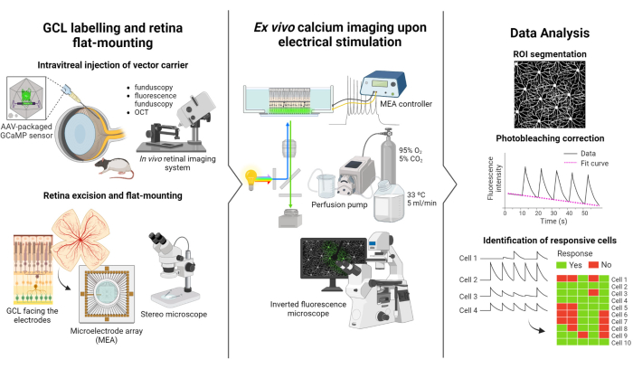
この研究で記述されているプロトコルは、Weitz et al.12 によって実施された蛍光イメージングおよび電気刺激研究に基づいています。プロトコルは、(1)GCLの蛍光標識とMEAへの網膜のフラットマウント(図1-左)、(2)電気刺激中のGCLのカルシウム活性の可視化(図1-中央)、および(3)画像データの抽出、処理、および解釈(図1-右)の3つの主要部分で構成されています。
まず、図1-左に示すように、Long Evansラットにイメージングセッションの前にAAV2-CAG-GCaMP5Gを硝子体内注射します。このベクターの最適なウイルス発現は、注射後2〜3週間で起こります12,18。動物に完全に麻酔をかけた後、30gの針を使用してパイロットホールを作成し、逆流を防ぐために精密シリンジに取り付けられた36gの鈍針を使用して、5μLのAAV2-CAG-GCaMP5Gを硝子体にゆっくりと注入します。ウイルス発現中、in vivo網膜イメージングシステムを使用して術後の網膜の状態を評価し、OCT画像で網膜層を詳細に視覚化します。遺伝子発現が達成されると、実体顕微鏡と高精度の解剖ツールを使用して、眼カップから網膜を慎重に抽出します。この時点から、組織は酸素化された培地で操作され、サンプルが保存されます。切除した網膜は、GCLを上に向けて、安定性を確保し、サンプルの浮遊を防ぐためにフラットマウント用に設計されたプラットフォームに取り付けられます。サンプルは、GCLを電極に向け、MEA表面にマウントされます。
次に、MEAを倒立蛍光顕微鏡のインターフェースボードに取り付けます(図1中央)。網膜サンプルは、灌流システムを使用して33°Cで酸素化培地で灌流されます。サンプルは、この構成で数時間維持できます。所望の刺激スキームがプログラムされ、画像が毎秒10フレームの速度で取得されます。適用された電気刺激パラメータに従って映画に名前を付けることをお勧めします。画像取得は、刺激のないベースラインフレームを取得するために、刺激の開始前に開始する必要があり、これはネガティブコントロールとして機能します。
最後に、 図1-右に示すように、細胞体細胞をセグメント化することにより、タイムラプス画像からデータを抽出します。データを当てはめることで光退色効果を補正し、反応性細胞を同定します。応答性細胞は、刺激中にベースラインを2.5倍上回る蛍光ピークを持つ細胞として定義されます。細胞が5回の刺激のうち3回に反応する場合、その細胞はその特定の刺激に応答していると見なされます。

図1:研究の概要。 (左)網膜のGCLを蛍光標識してサンプルをマウントし、(中央)MEAによる電気刺激による ex vivo 記録の準備をセットアップし、(右)カルシウムイメージングデータを解析して応答性細胞を分類するためのプロトコルの概略図。 この図の拡大版をご覧になるには、ここをクリックしてください。
硝子体内注射網膜
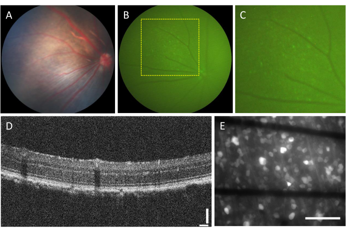
硝子体内注射に関連する合併症の発生率は非常に低いです。ただし、注射する成分に関係なく、手術自体から発生する可能性のある合併症がいくつかあります。これらの合併症には、白内障形成、硝子体出血、眼圧の上昇、眼内炎などがあります23。これらの合併症が手術によって引き起こされているかどうかを判断するには、動物は眼底検査とOCTを使用して手順の前に評価を受ける必要があります。注射の3日後、動物をフォローアップする必要があります。 図2A〜Dに、健康な注射動物の網膜が示されている。2週間の注射後、RGCは蛍光を発現し始め、蛍光眼底鏡検査で可視化することができます(図2B、C)。OCT画像は、網膜層の配置と厚さを詳細に視覚化し(図2D)、特に網膜剥離を評価する場合に、眼底検査と比較してより高い解像度を提供します。網膜を平らに取り付け、倒立蛍光顕微鏡で画像化すると、細胞と軸索束を区別することが可能になります。他のカルシウム指示薬とは異なり、GCaMP指示薬は細胞質に限定され7、蛍光は核から排除されます(図2E)。

図2:硝子体内注射された網膜の代表的な画像。 (A)眼底鏡検査、(B)蛍光眼底鏡検査、(C)蛍光眼底検査のズームイン、(D)OCT画像、(E)厚さ500μmのホウケイ酸ガラスにグラフェンベースの電極を備えたカスタムMEAに取り付けられた切除網膜の落射蛍光画像。(E)では、黒い線がTi/Auトレースに対応しています。スケールバー:115 μm(D)および100 μm(E)。 この図の拡大版をご覧になるには、ここをクリックしてください。
電極とGCL接点
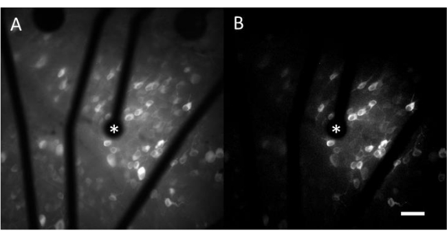
神経応答を効果的に喚起するためには、平らに取り付けられた網膜がMEAの表面に密着していることを確認することが重要です。これを確認する簡単な方法は、セルと電極が同じ焦点面にあるかどうかを視覚的に確認することです(図3A)。細胞が電極と同じ焦点面にない場合(図3B)、接触が最適ではないことを示し、効果的な刺激が少なくなります。

図3:電極とGCLの接触。 (A)セルと電極(アスタリスク)が同じ焦点面にあります。(B)セルと電極が同じ焦点面になく、その領域での電気刺激の接触が最適でないことを示します。 この図の拡大版をご覧になるには、ここをクリックしてください。
MEAによる電気刺激によるEx vivoカルシウムイメージング
カルシウムイメージングから得られたデータは、電気刺激に応答する数百の細胞の神経活動をモニターするタイムラプス画像で構成されています。閾値上刺激は細胞体細胞へのカルシウム流入を引き起こし、蛍光強度の急激な変化をもたらします(ビデオ1)。このプロトコルにより、電極、MEA、および/または刺激アルゴリズムが神経組織で望ましい応答を引き出すかどうかを判断できます。MEA上の電極のサイズとピッチ、および研究対象の組織の割合によって、選択する適切な対物レンズ倍率が決まります。通常、直径が5 μmから100 μmの範囲の単一電極刺激研究には、20〜25倍の対物レンズ倍率が適しており(図4A)、約600 μm x 600 μmのFOVを提供します。複数の電極による刺激を伴う実験では、約2 mm x 2 mmのより広い領域を評価するために、4〜10倍の対物レンズ倍率が必要になる場合があります。応答性セルは、タイムラプス動画の標準偏差画像投影を生成することによって容易に識別することができる(図4B および ビデオ1)。

図4:直径25μmの電極による電気刺激によるGCLのカルシウムイメージング。 (A)直径25μmの多孔質グラフェン系電極からの電気刺激に応答する細胞を明瞭に描写した60秒タイムラプス動画の最大投影と、(B)標準偏差投影。刺激電極はアスタリスクで示されます。スケールバー:50 μm。 この図の拡大版をご覧になるには、ここをクリックしてください。
制御された刺激によるカルシウム動態の経時的解析
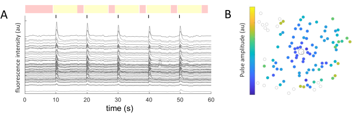
同定された各細胞体細胞について、平均強度値を経時的に抽出した。 図5A は、応答性細胞からの光退色補正されたカルシウムの痕跡を示しています。この例では、60 秒の画像取得中に、10 秒ごとに 5 つのバースト (陰極ファースト、40 サイクル、1 ミリ秒の持続時間、2 μA の振幅) が送達されました (黒い線で表示)。特定の実験では、同じ5つのパルス列を適用して、応答の一貫性をテストします。非刺激期間中にキャプチャされたフレーム(赤で強調表示)は、線形フィットを実行するために使用され、光退色効果を補正します。
応答する細胞が特定され、その座標(x,y)が刺激電極に対して相対的にわかれば、細胞を活性化するために必要な電流と刺激電極からの距離の関係を調べることができます(図5B)。予想通り、刺激電極に近い位置にあるセルは、応答を誘発するためにより低い電流値を必要とします。

図5:電気誘発応答の表現。 (A)60秒の画像取得中に10秒ごとにパルス列(二相性、陰極ファースト、40サイクル、持続時間1ms、振幅2μA)を5バーストしたときの細胞体のカルシウム微量(黒線)。非刺激期間(赤で強調表示されたフレーム)と刺激期間(黄色で強調表示されたフレーム)が表示されます。ベースライン信号(非刺激期間の二乗平均平方根)を2.5倍上回るトレースは、誘発反応と見なされます。5つの刺激期間のうち3つで応答する細胞は、応答細胞に分類されます。(B)刺激電極(黒丸)と細胞(灰色の丸)を示すカルシウム活性分布図。カラーコードは、細胞応答を誘発するのに必要な最小パルス振幅を表します。 この図の拡大版をご覧になるには、ここをクリックしてください。
動画1:直径25μmの電極による電気刺激によるGCLのカルシウムイメージング。 このビデオは、直径25μmの多孔質グラフェンベースの電極からの電気刺激による蛍光強度の違いを示しています。左側は元のムービー、右側は応答細胞を簡単に識別できる標準偏差投影を示しています。スケールバー:50 μm。 このビデオをダウンロードするには、ここをクリックしてください。
ディスカッション
ここで説明するプロトコルは、MEAを与えられた電気刺激時にラット網膜GCLで発生するカルシウム動態を研究するのに役立ちます。これは信頼性が高く管理しやすい方法ですが、特にGCLを効率的に均一に標識し、網膜を適切に取り付けて最適な組織と電極の接触を確保するには、ある程度のトレーニングが必要です。このプロトコルはげっ歯類に特異的であり、別の実験室種に適用する場合は適合させる必要があります。方法論の重要なポイント、変更、および制限が詳細に示されています。
硝子体内注射
注射は眼の遺伝子送達に広く使用されており、硝子体内注射が好ましい手順です。それらは、光受容体と網膜色素上皮(RPE)の間に目的の分子を直接導入し、網膜剥離のリスクを冒す網膜下注射と比較して、より安全で侵襲性が低いことが証明されています10。ただし、特にげっ歯類モデルでこれらの注入を行う場合は制限があります。硝子体液はゼラチン状で、ウイルスの拡散を妨げます。さらに、げっ歯類の目の水晶体は大きいため、針を傷つけずに挿入するのは簡単ではありません。精密シリンジの針はデリケートで、頻繁に交換する必要があります。閉塞を防ぐために、使用の前後に毎回脱イオン水で洗い、定期的に交換してください。さらに、溶液の逆流や眼圧の変化を防ぐために、内容物をゆっくりと注入します。.網膜全体で大きく均一な蛍光を実現するには、練習が必要な場合があります。
網膜細胞形質導入
ウイルスベクターはin vivo遺伝子送達のための優れた方法であり、AAVは網膜細胞の形質導入に広く用いられている10。それらは、人間の失明を引き起こすいくつかの網膜症の治療薬として承認されています24。しかし、それらのキャリア容量は、必要な調節要素(例えば、プロモーター)を含めて5 kbに制限されています10,25。複数の血清型が利用可能であり、それぞれが異なる屈性を持っています。導入する遺伝子と形質導入する細胞に基づいて、最適なAAVを選択します26。RGCのラベリングには、AAV227の使用が推奨されます。
遺伝子発現ウィンドウ
AAV2-CAG-GCaMP5Gの最適なウイルス発現は、注射後2〜3週間です12,18。その時間枠を超えると、トランスフェクションされた細胞の核は蛍光を発し、細胞は刺激に反応しなくなり、最終的には死滅します7,28,29。これは、核に転座するGCaMPインジケーターの過剰発現によるものです。最適な遺伝子発現のための時間枠は、ウイルスベクターおよび選択されたプロモーター30によって異なり、このプロトコルを進める前に実験的に決定される必要がある。
組織-電極接触
最適で再現性のある結果を得るには、組織と電極の良好な接触を達成することが重要です。接触不良は、通常、網膜の自然な湾曲が原因です。1つのアプローチは、網膜を4分の1に切断し、一度に1つのセクションをマウントして画像化することです。網膜の小さな部分をよりよく平らにすることができ、その結果、MEAの表面とのより効果的な接触が得られます。接触不良のもう一つの潜在的な理由は、硝子体液の存在です。網膜上インプラントを模擬した刺激実験を行う場合、網膜切除中に硝子体液は電流に対する絶縁体として機能する可能性があるため、慎重に除去することが重要です。ここでは、電極とセルを同一焦点面内で可視化することにより、接触が十分であるかどうかをチェックする簡単な方法について説明する。
ex vivo網膜測定の代替法は、電極の表面で直接ニューロンを成長させることです。海馬ニューロン31などのニューロンの初代培養は、新規刺激デバイスの機能性を評価するための初期試験に有用であり得る。しかし、このアプローチは依然として実験動物の使用を必要とし、刺激に対するシナプス応答を評価するために重要な網膜ネットワークの複雑さを表すものではありません。
電極および電極トレースの下のセルを可視化するために、酸化インジウムスズ(ITO)などの透明材料で作製されたMEAを使用できます19,20,32。光学的測定に加えて、電気刺激に対するGCL活性は、電気的記録によって評価することができます。MEAは、組織の局所電界電位(LFP)を記録するために使用できます。ただし、各電極が複数のセルからの活性を同時に捕捉するため、空間分解能が損なわれます(電極の寸法によって異なります)。光記録はこの制限を克服し、より高い空間分解能マッピングを提供します。その主な利点は、シングルセル分解能で大きなFOVを測定しながら、アクティブセルと非アクティブセルを区別できることです。すべての細胞活動レポーターの中で、カルシウム指標はよく説明されており、最も一般的に使用されています33。
開示事項
著者は、原稿に追加する開示事項を持っていません。
謝辞
技術支援をしてくれたMerche Rivas氏、Angel Sandoval氏、Jesús Planagumà氏、Jordi Cortés氏、Sandra Ortonobés Lara氏、Alina Hirschmann氏(ICFO-Institut de Ciències Fotòniques)、眼科学研究グループのAnna Duarri氏(VHIR、Vall d'Hebron Institute of Research)には、硝子体内注射と in vivo 網膜イメージングのサポートをしてくれたことに感謝します。
この作業を支援した資金提供団体は、Fundació CELLEX;Fundació Mir-Puig;Ministerio de Economía y Competitividad - Severo Ochoa program for Centres of Excellence in R&D (CEX2019-000910-S, [MCIN/AEI/10.13039/501100011033]);CERCAプログラムによるカタルーニャ州政府。Laserlab-Europe (EU-H2020 GA no. 871124);ラ・カイシャ財団(LCF/HR19/52160003);とFondo Social Europeo(PRE2020-095721、MC)。
資料
| Name | Company | Catalog Number | Comments |
| 20x NA 0.75 S Fluor air objective | Nikon | CFI Super Fluor 20X | - |
| 3.5 cm Cell culture dish | Nunc | 12-565-90 | - |
| 30 G needle | VWR | 613-5373 | - |
| 36 G blunt needle | World Precision Instruments | NF36BL-2 | - |
| 6 cm Cell culture dish | Nunc | 12-565-94 | - |
| AAV2-CAG-GCaMP5G | Vector Biolabs | - | - |
| Ames' Medium | Sigma Aldrich | A1420 | - |
| Blade | Swann-morton | 0308 | - |
| Camera | Hamamatsu | ORCA Flash v4.0 | - |
| Carbogen | Air liquide | - | - |
| Curved-forceps | - | - | - |
| Fine spring-scissors | FST | 91501-09 | - |
| FITC filter cube | Nikon | Standard series | - |
| Fluorescent lamp | Nikon | C-HGFI | - |
| Fluorescent stereomicroscope | Nikon | SMZ25 | - |
| HBSS | Capricorn | HBSS-1A | - |
| ImageJ/FIJI | NIH | v1.50i | - |
| In vivo retinal imaging system | Phoenix Research Laboratories | Micron III | - |
| Inverted fluorescence microscope | Nikon | Eclipse Ti | - |
| Isofluorane | Arrane Baxter Laboratories | - | - |
| Long-Evans rat | Janvier | - | - |
| MATLAB (Version R2021b) | Mathworks | - | - |
| Media filters | Merckmillipore | SCGPS02RE | - |
| Methocel 2% | Omni Vision | - | - |
| Microelectrode array (MEA) | - | Custom-made | |
| NaHCO3 | Thermofisher | 42427 | - |
| Penicillin/Streptomycin 100x | Thermofisher | 15140122 | - |
| Phenylephrine | Alcon Cusí Laboratories | 653437.3 | 100 mg/mL |
| Plastic pipette | VWR | 612-1793 | - |
| Porous membrane | Merckmillipore | #JVWP01300 | - |
| Precision syringe | World Precision Instruments | 10 µl Nanofil | - |
| Prescaina | Llorens | - | Oxybuprocaine chlorhydrate (2 mg/mL), local anesthetic |
| Rat nasal mask | Xenotec | XRK-RA | - |
| Small curved-forceps | Bbraun | AESCBD311R | - |
| Spring-scissors | FST | 15040-11 | - |
| Stereo microscope | Zeiss | Stemi 2000 | - |
| Straight forceps | FST | 11252-20 | - |
| Suture filament | Vitrex Medical | 4328 | Nilon monofilament, 7/0, DS12 |
| Tobradex | Alcon Cusí Laboratories | - | Tobramycin (3 mg/mL) and dexamethasone (1 mg/mL) |
| Tropicamide | Alcon Cusí Laboratories | 653486 | 10 mg/mL |
| Washer | Thorlabs | W8S038 | - |
参考文献
- Bourne, R. R. A., et al. Prevalence and causes of vision loss in high-income countries and in Eastern and Central Europe in 2015: Magnitude, temporal trends and projections. British Journal of Ophthalmology. 102 (5), 575-585 (2018).
- Li, J. Q., et al. Prevalence and incidence of age-related macular degeneration in Europe: a systematic review and meta-analysis. British Journal of Ophthalmology. 104 (8), 1077-1084 (2020).
- Roska, B., Sahel, J. A. Restoring vision. Nature. 557 (7705), 359-367 (2018).
- Hornig, R., Velikay-Parel, M. Retina implants. Implantable Sensor Systems for Medical Applications. , Elsevier. 469-496 (2013).
- Lewis, P. M., et al. Advances in implantable bionic devices for blindness: a review. ANZ Journal of Surgery. 86 (9), 654-659 (2016).
- Weiland, J. D., Walston, S. T., Humayun, M. S. Electrical stimulation of the retina to produce artificial vision. Annual Review of Vision Science. 2, 273-294 (2016).
- Tian, L., et al. Imaging neural activity in worms, flies and mice with improved GCaMP calcium indicators. Nature Methods. 6, 875-881 (2009).
- Chen, T. -W., et al. Ultrasensitive fluorescent proteins for imaging neuronal activity. Nature. 499, 295-300 (2013).
- Nakai, J., Ohkura, M., Imoto, K. A high signal-to-noise Ca2+ probe composed of a single green fluorescent protein. Nature Biotechnology. 19, 137-141 (2001).
- Sahu, B., Chug, I., Khanna, H. The ocular gene delivery landscape. Biomolecules. 11 (8), 1135(2021).
- Hanlon, K. S., et al. A novel retinal ganglion cell promoter for utility in AAV vectors. Frontiers in Neuroscience. 11, (2017).
- Weitz, A. C., et al. Imaging the response of the retina to electrical stimulation with genetically encoded calcium indicators. Journal of Neurophysiology. 9 (7), 1979-1988 (2013).
- Briggman, K. L., Euler, T. Bulk electroporation and population calcium imaging in the adult mammalian retina. Journal of Neurophysiology. 105 (5), 2601-2609 (2011).
- Baden, T., Berens, P., Franke, K., Román Rosón, M., Euler, T. The functional diversity of retinal ganglion cells in the mouse. Nature. 529, 345-350 (2016).
- Zhang, Y., et al. Fast and sensitive GCaMP calcium indicators for imaging neural populations. Nature. 615, 884-891 (2023).
- Meyer, E. L., Jenkins, C., Rengarajan, K. NIH Guidelines April 2019. Applied Biosafety. 24, Preprint at https://doi.org/10.1177/1535676019871146 (2019).
- Akerboom, J., et al. Optimization of a GCaMP calcium indicator for neural activity imaging. Journal of Neuroscience. 32 (40), 13819-13840 (2012).
- Chang, Y. -C., Walston, S. T., Chow, R. H., Weiland, J. D. GCaMP expression in retinal ganglion cells characterized using a low-cost fundus imaging system. Journal of Neural Engineering. 14 (5), 056018(2017).
- Weitz, A. C., et al. Improving the spatial resolution of epiretinal implants by increasing stimulus pulse duration. Science Translational Medicine. 7 (318), 1-12 (2015).
- Chang, Y. C., Ghaffari, D. H., Chow, R. H., Weiland, J. D. Stimulation strategies for selective activation of retinal ganglion cell soma and threshold reduction. Journal of Neural Engineering. 16 (2), 026017(2019).
- Im, M., Fried, S. I. Temporal properties of network-mediated responses to repetitive stimuli are dependent upon retinal ganglion cell type. Journal of Neural Engineering. 13 (2), 025002(2016).
- Jensen, R. J., Ziv, O. R., Rizzo, J. F. Thresholds for activation of rabbit retinal ganglion cells with relatively large, extracellular microelectrodes. Investigative Ophthalmology & Visual Science. 46 (4), 1486-1496 (2005).
- Ramos, M. S., et al. Patient-reported complications after intravitreal injection and their predictive factors. Ophthalmology Retina. 5 (7), 625-632 (2021).
- Vandenberghe, L. H., Auricchio, A. Novel adeno-associated viral vectors for retinal gene therapy. Gene Therapy. 19 (2), 162-168 (2012).
- Zin, E. A., Ozturk, B. E., Dalkara, D., Byrne, L. C. Developing new vectors for retinal gene therapy. Cold Spring Harbor Perspectives in Medicine. , a041291(2023).
- Haggerty, D. L., Grecco, G. G., Reeves, K. C., Atwood, B. Adeno-associated viral vectors in neuroscience research. Molecular Therapy-Methods & Clinical Development. 17, 69-82 (2020).
- Hellström, M., et al. Cellular tropism and transduction properties of seven adeno-associated viral vector serotypes in adult retina after intravitreal injection. Gene Therapy. 16 (4), 521-532 (2009).
- Resendez, S. L., et al. Visualization of cortical, subcortical and deep brain neural circuit dynamics during naturalistic mammalian behavior with head-mounted microscopes and chronically implanted lenses. Nature Protocols. 11, 566-597 (2016).
- Yang, Y., et al. Improved calcium sensor GCaMP-X overcomes the calcium channel perturbations induced by the calmodulin in GCaMP. Nature Communications. 9, 1504(2018).
- Nieuwenhuis, B., et al. Improving adeno-associated viral (AAV) vector-mediated transgene expression in retinal ganglion cells: comparison of five promoters. Gene Therapy. 30, 503-519 (2023).
- Cunquero, M., Aguilar, E., Loza-Alvarez, P., Planagumà, J. Hippocampal neuronal cultures to detect and study new pathogenic antibodies involved in autoimmune encephalitis. Journal of Visualized Experiments. 184, e63829(2022).
- Behrend, M. R., Ahuja, A. K., Humayun, M. S., Chow, R. H., Weiland, J. D. Resolution of the epiretinal prosthesis is not limited by electrode size. IEEE Transactions on Neural Systems and Rehabilitation Engineering. 19 (4), 436-442 (2011).
- Grienberger, C., Konnerth, A. Imaging calcium in neurons. Neuron. 73 (5), 862-885 (2012).
転載および許可
このJoVE論文のテキスト又は図を再利用するための許可を申請します
許可を申請さらに記事を探す
This article has been published
Video Coming Soon
Copyright © 2023 MyJoVE Corporation. All rights reserved