
Aby wyświetlić tę treść, wymagana jest subskrypcja JoVE. Zaloguj się lub rozpocznij bezpłatny okres próbny.
Method Article
Development of Sulfidogenic Sludge from Marine Sediments and Trichloroethylene Reduction in an Upflow Anaerobic Sludge Blanket Reactor
W tym Artykule
Podsumowanie
Microbial sulfate reduction is a process of great importance in environmental biotechnology. The success of the sulfidogenic reactors depends among other factors on the microbial composition of the sludge. Here, we present a protocol to develop sulfidogenic sludge from hydrothermal vents sediments in a UASB reactor for reductive dechlorination purposes.
Streszczenie
The importance of microbial sulfate reduction relies on the various applications that it offers in environmental biotechnology. Engineered sulfate reduction is used in industrial wastewater treatment to remove large concentrations of sulfate along with the chemical oxygen demand (COD) and heavy metals. The most common approach to the process is with anaerobic bioreactors in which sulfidogenic sludge is obtained through adaptation of predominantly methanogenic granular sludge to sulfidogenesis. This process may take a long time and does not always eliminate the competition for substrate due to the presence of methanogens in the sludge. In this work, we propose a novel approach to obtain sulfidogenic sludge in which hydrothermal vents sediments are the original source of microorganisms. The microbial community developed in the presence of sulfate and volatile fatty acids is wide enough to sustain sulfate reduction over a long period of time without exhibiting inhibition due to sulfide.
This protocol describes the procedure to generate the sludge from the sediments in an upflow anaerobic sludge blanket (UASB) type of reactor. Furthermore, the protocol presents the procedure to demonstrate the capability of the sludge to remove by reductive dechlorination a model of a highly toxic organic pollutant such as trichloroethylene (TCE). The protocol is divided in three stages: (1) the formation of the sludge and the determination of its sulfate reducing activity in the UASB, (2) the experiment to remove the TCE by the sludge, and (3) the identification of microorganisms in the sludge after the TCE reduction. Although in this case the sediments were taken from a site located in Mexico, the generation of a sulfidogenic sludge by using this procedure may work if a different source of sediments is taken since marine sediments are a natural pool of microorganisms that may be enriched in sulfate reducing bacteria.
Wprowadzenie
One of the most important contributions to environmental biotechnology was the design of bioreactors in which the sludge used (inoculum) was able to perform under sulfate reducing conditions. Sulfate reduction (SR) allows the treatment of wastewater streams that contain high concentrations of sulfate in addition to the simultaneous removal of COD, heavy metals and organic pollutants, a fact that makes SR a desirable characteristic of the sludge 1. Some examples of effluents contaminated with sulfate come from tannery, paper, pharmaceutical and chemical manufacturing industries 1. However, most of the literature refers to sulfidogenic sludge when methanogenic granular sludge has been adapted to sulfidogenesis 2. This adaptation is commonly attained by manipulating the COD/SO42- ratio in the bioreactor and adding chemicals to inhibit methanogens in the sludge 2,3. In addition to the long time that may require the formation of the sulfidogenic granules, the competition between methanogens and sulfate reducers and the tolerance of the sludge to high concentrations of sulfide are some of the main problems that may arise if the sulfidogenic sludge used in the bioreactor is obtained from the adaptation of predominantly methanogenic sludge to sulfate reducing conditions. In this work, we describe the procedure to obtain a predominantly sulfidogenic sludge from hydrothermal vents sediments (Punta Mita, Nayarit, Mexico) in an upflow anaerobic sludge blanket reactor (UASB), then we evaluate its sulfate reducing activity over time and conduct an experiment to evaluate its application on reductive dechlorination. The location of the sediments was chosen because it has been reported that in that site there is formation of sulfides due to the sulfate reducing activity exhibited by the microbial community inhabiting that particular place4.
There are several advantages in obtaining this sulfidogenic sludge from sediments over adapting methanogenic granular sludge to sulfidogenesis. Some of these advantages are: (1) it is not necessary to form granules for the bioreactor to operate, (2) the sludge tolerates relatively high concentrations of sulfide compared to others UASB that operate with adapted methanogenic sludge, and (3) there is no competition for substrate with methanogens even if acetate is used in the mixture of volatile fatty acids that is included in the culture medium to promote the formation of the sludge.
This procedure was followed to promote sulfidogenesis because marine sediments are a natural pool of a wide variety of microorganisms such as sulfate reducing bacteria, fermenting bacteria and dehalogenating bacteria just to mention a few 5,6. The type of consortium developed from marine sediments by using this protocol may exhibit efficiency in sulfate reduction and therefore, high sulfate reducing activity over time and higher tolerance to sulfide at concentrations higher than the reported as toxic to methanogens and sulfate reducing bacteria. On the other hand, it is likely that the dehalogenating capability is also shown in the sediments by following the protocol proposed here but it may depend on the original microbial community. This assumption is done based on the fact that reductive dechlorination can occur either by respiration or cometabolism, both conditions that may be promoted in the marine microbial community 7. The cultivation of the sediments to obtain the sludge was conducted by using a mixture of acetate, propionate and butyrate as substrate because these volatile fatty acids are used by several strains of sulfate reducing bacteria. These acids are also the type of carbon compounds frequently found in marine sediments, according to several reports in literature on carbonaceous material in sea sediments5,6.
Finally, some of the most toxic compounds that are found in groundwater and other water bodies around the world are the chlorinated solvents such as trichloroethylene (TCE) or perchloroethylene (PCE). These compounds are toxic not only to the human being but also to microorganisms, particularly TCE, which is still considered a priority pollutant by the Environmental Protection Agency in the US8. In this work we proposed an experiment in which the sulfidogenic sludge is tested on its capability of reducing TCE at concentrations that are in the range reported for chlorinated compounds biodegradation under methanogenic conditions9,10. It is worth mentioning that most of the research on biodegradation of chlorinated compounds has been conducted under methanogenic conditions 9,10. We consider that the experiment with TCE proposed in this protocol is a good example of the potential applications of the sludge. The objective of this experiment was to evaluate the tolerance of the sludge to the TCE and the TCE effect on the sulfate reducing activity. Taking into account that most of the research on biodegradation of chlorinated compounds is carried out under methanogenic conditions, this protocol suggests the formation of a sludge may be used to simultaneously: (1) remove sulfate, (2) remove COD and (3) remove chlorinated compounds. A further step could be to evaluate the sludge on the simultaneous removal of TCE and heavy metals (in addition to sulfate and COD), two conditions that cannot be evaluated under methanogenic conditions.
Protokół

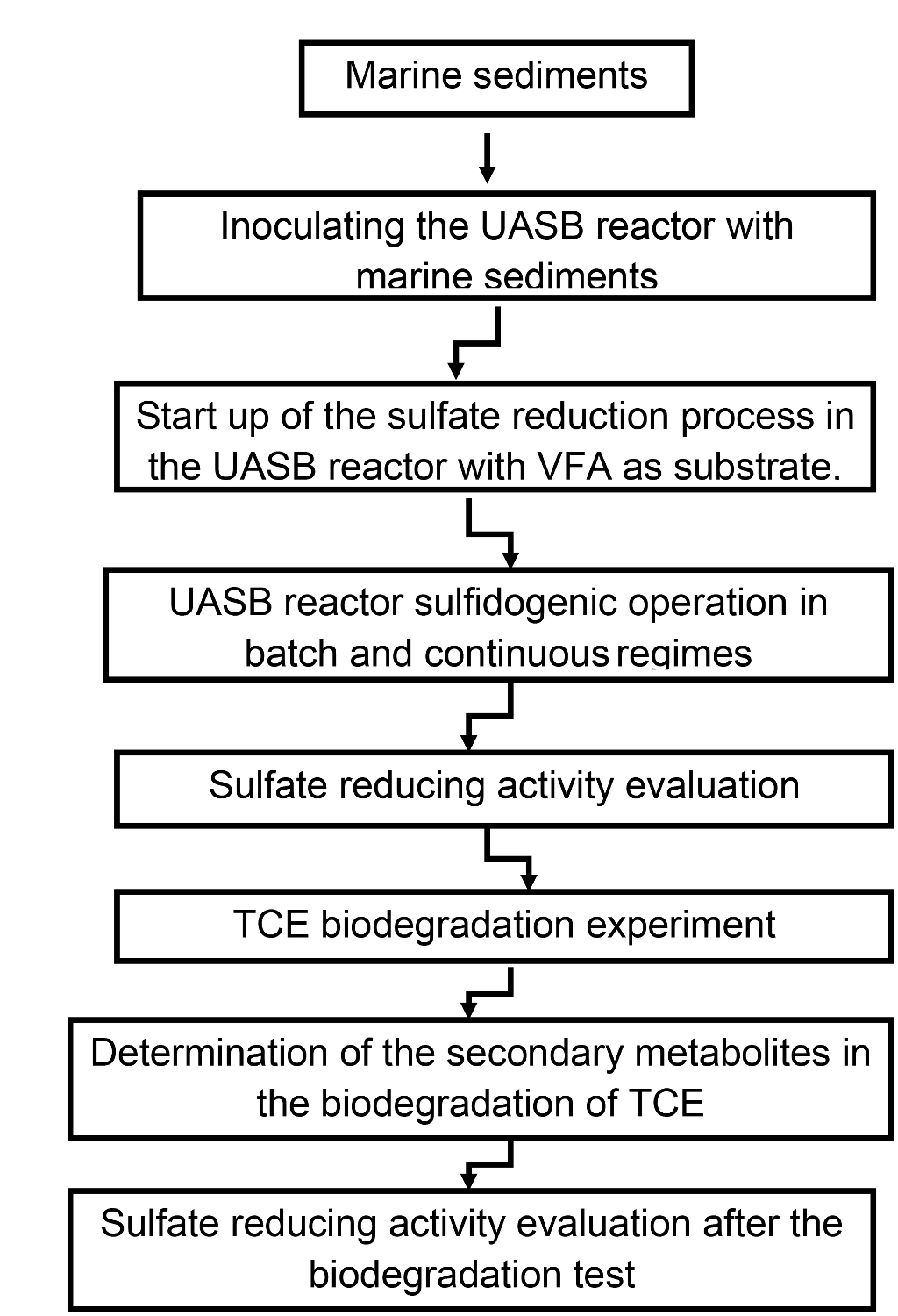
Figure 1. Scheme for the steps of the protocol. Please click here to view a larger version of this figure.
1. Collect Marine Sediments for the Formation of the Sludge
- Identify an approachable subsea area either close to hydrothermal vents (due to the presence of sulfides, which may indicate a higher sulfate reducing activity) or to an area where debris of organic matter are detectable.
- For the purpose of this work, take approximately 3 or 4 kg of sediment and drain the water off the samples. Place the samples in dark plastic bags. No refrigeration is needed.
- Once in the lab, keep the bags with the samples in the refrigerator if they are not going to be used immediately. For the purpose of this work, samples can be in the refrigerator for weeks or months before using them.
- Take a large portion of the sediment sample (i.e., 1 or 2 kg) and use an appropriate mesh (0.2 cm) to eliminate from the sediments the large debris of carbonaceous material that may be found or some rocks that may be present.
Note: In this case a mesh of 0.20 cm diameter (0.0767 in) was used but it may be of a different size according to the size of the particles in the sample.- After passing the sediment through the mesh, mix the portion selected to promote that the portion is homogeneous.
- Take separated smaller samples (i.e., 2 to 3 g) to determine the volatile suspended solids (VSS) content by following the standard methods 11 .
Note: See Figure 2 for steps 1.2 to 1.4.

Figure 2. Photographs of the sediment samples. (A) Sediment samples just after being taken. (B) Sediment sample after passing through the mesh. (C) Sample taken for weighing prior to volatile suspended solids (VSS) determination. The Petri dish does not need to be sterilized. Please click here to view a larger version of this figure.
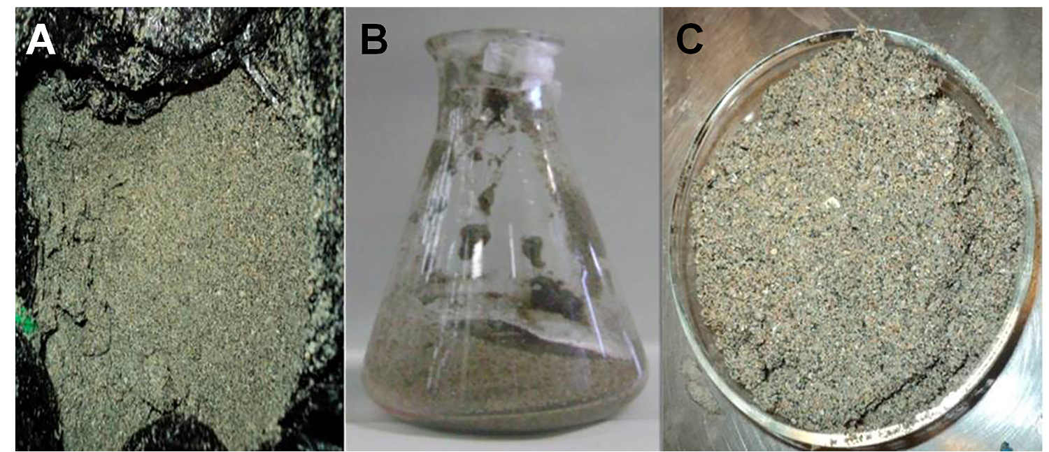
2. Bioreactor Set Up
- For the purpose of this work, use a UASB glass reactor with a total working volume of 3 L. Alternatively, use a 1 or 2 L volume glass reactor.
- Based on the VSS content of the sediments calculate the amount of sediment to be used as inoculum to obtain 5 g of VSS in 1 L.
- Take into account that if the amount of sediment after calculation is too large, then approximately 25% to 30% volume of the bioreactor should be occupied by the sediments instead.
- Record the VSS content since it will change when the microbial community is enriched in the bioreactor. The VSS content is needed for the calculations of sulfate reducing activity in the bioreactor.
- Ensure that the final concentration of the basal medium and buffer solution in the bioreactor is similar to the reported by Guerrero-Barajas et al. (2014)12.
- Ensure that the final volumes of the sediments, basal medium, buffer solution and volatile fatty acids are equal to the final working volume of the reactor. The basal medium recipe12 contains the appropriate concentrations for the trace metals and vitamins solution.
- Prepare a stock solution of basal medium and buffer solution in an appropriate concentration for the working volume of the reactor used (i.e., 2, 3 or 4 fold more concentrated than the reported in step 2.4) to ensure that when it is diluted, it is at the concentration reported by Guerrero-Barajas et al. (2014)12).
Note: The stock solution for the basal medium is always necessary, however, the buffer solution is only needed at the start up. It is not necessary to add buffer solution after this time. - Prepare a stock solution of volatile fatty acids: acetate, propionate and butyrate in a 2.5:1:1 COD proportion. Take into account for the calculations the sodium acetate included in the basal medium. The final COD concentration in the reactor must be 2.7 g/L.
Caution: Prepare this solution in a fume hood. Wear nitrile gloves and goggles for the preparation of this solution. Take into account the stoichiometry of the reactions of sulfate with the volatile fatty acids that is shown in Figure 3. - Prepare a stock solution of sodium sulfate (Na2SO4) in an appropriate concentration to deliver to the reactor a final concentration of 4,000 mg/L of the sulfate ion (SO42-). Alternatively, include the amount of sulfate required in the basal medium instead of adding it from a stock solution as long as the final sulfate (SO42-) concentration is right.
- Place the sediments in the reactor mixed with a portion of the basal medium to make sure they reach the bottom of the reactor.
- Add the rest of the basal medium and buffer solution mixed with the volatile fatty acids solution and the sulfate solution. Make sure that the solution of volatile fatty acids is poured into the liquid. Note: Conduct this step in a fume hood.
- Set the connections and pipelines of the reactor to the recycling pump. Set the recycling flow rate at 60 ml/min. Set the bioreactor in the temperature chamber at 34 °C. Regularly check that the temperature variations are small (i.e., 34 ± 1.7 °C)
- Set the connections to the gas displacement column.
Note: See Figure 4 for steps 2.1 to 2.5.

Figure 3. Stoichiometry of sulfate reduction with VFA (acetate, propionate and butyrate). Please click here to view a larger version of this figure.

Figure 4. UASB reactor. (A) Initial time. (B) Continuous regime after 300 days of operation. Please click here to view a larger version of this figure.
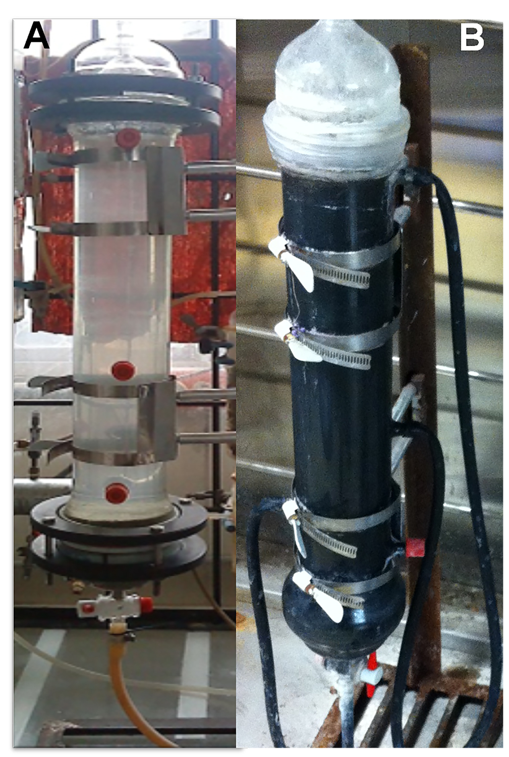
3. Operation of the Reactor to Promote Sulfidogenesis and Growth of the Microorganisms
Note: Allow for the inoculum to consume the volatile fatty acids and sulfate. For this purpose, wait for one week to carry out the first analysis for sulfate, sulfide and COD consumption.
- After one week of incubation take a sample of 5 to 7 ml of the liquid to conduct analysis for COD, sulfate and sulfide content and pH following standard methods 11, 13.
- Analyze sulfide in the liquid spectrophotometrically (at a wavelength (λ) of 670 nm) by following the methylene blue method 13.
- Place 5 ml of a zinc acetate solution (2% w/w) in a 25 ml volumetric flask, add quickly 200 µl of the sample to the zinc acetate solution.
- Add 2.5 ml of an N,N-dimethyl-p-phenylenediamine oxalate (DMP) solution (0.2% w/w in 20% H2SO4) and 125 µl of the iron (III) ammonium sulfate solution (10% w/w in 2% H2SO4) and complete with distilled water the 25 ml in the volumetric flask. Wait 30 min for the reaction to occur, time at which the blue color is stabilized. 13.
Note: Wait at least 15 min, but not more than 60 min to test the samples in the spectrophotometer. Conduct the reading of the blue final solution in the spectrophotometer.
- Analyze sulfate according to standard methods 11. Here, quantify sulfate as barium sulfate by using a turbidimetric method.
- Place 5 ml of a conditioning solution (hydrochloric acid HCl 1:1) in a volumetric flask of 25 ml, add 1 ml of the previously centrifuged sample (at 11,320 × g), complete the 25 ml of the volumetric flask with distilled water and add 1 g of barium chloride.
- Mix the solution for 1 min in a vortex. Wait for 4 min for the barium sulfate to form and read the sample in the spectrophotometer at a wavelength (λ) of 420 nm 11.
- Analyze COD according to standard methods 11. Alternatively, use a COD determination kit.
- Prior to the COD determination, centrifuge the sample thoroughly (at 11,320 x g) to remove the remaining sulfide that may interfere in the determination. If necessary, centrifuge twice: the first time immediately after taking the sample and the second time wait 6 or 8 hr and then conduct the COD analysis.
- Add 2 ml of sample to a reaction vial of the COD determination kit, seal the vial and homogenize the mixture by gentle agitation. Prepare a blank by adding 2 ml of distilled water to another reaction vial and homogenize the mixture.
- Place the vials in the digestion reactor at 150 °C for 2 hr. Remove the vials and let them cool down in the dark. Take the readings of the vials in the spectrophotometer at a wavelength of 620 nm.
- Obtain the gas volume from the gas displacement column.
- Analyze sulfide in the liquid spectrophotometrically (at a wavelength (λ) of 670 nm) by following the methylene blue method 13.
- Wait for up to another 5 to 7 days until the sulfate is consumed. Sulfate and COD must be consumed in approximately 85% to 90% before a new fed batch is started.
- Once sulfate (and COD) are consumed, completely repeat step 2.4. Supply fresh medium and new nutrients for each batch.
- Repeat steps 3.1 and 3.2. At this point each batch should last between 7 and 10 days.
- When 3 to 4 batches have been completed, repeat step 2.4 but increase the COD concentration to 4 g/L.
- Repeat step 3.1 and step 3.2.
- Repeat step 3.3 but increase the COD concentration to 6 g/L.
- Repeat 3.6 and 3.6.1 gradually increasing COD concentration until it is 10 g/L.
Note: Make the graph that presents the sulfate concentration (mg/L) versus time (d).
- When sulfate consumption is over 80% in less than 24 hr and this occurs for more than one week, switch the operation of the reactor to continuous mode. For the continuous mode set the hydraulic retention time (HRT) at 24 hr and maintain the sulfate concentration at 4 g/L and the COD at 10 g/L.
Note: Over time the sulfate consumption should be faster.
4. Sulfate Reducing Activity Test
- Prior to this test make sure that the bioreactor under continuous regime presents less than 10% variation in the sulfate concentration remaining.
- At any given day, stop the reactor after one HRT cycle and conduct step 2.4. For step 2.4.3 use a COD concentration of 10 g/L.
- Once the bioreactor is fed, take 5 to 7 ml samples of the liquid and perform analysis for COD, sulfate, sulfide (step 3.1) and pH every hour. Record the gas volume produced.
- Calculate the sulfate reducing activity according to the literature 14.

SRA = sulfate reducing activity (mg COD-H2S)/gVSS*d
m H2S = sulfide concentration expressed as mg COD-H2S
VSS = volatile suspended solids concentration
t = time (d or hr)
- Make the corresponding graphs that show the percentage of sulfate consumption versus sulfide concentration over time in mg/L. Make the graphs that show percentage of COD consumption over time. Make the graphs that show pH variation over time.
5. Trichloroethylene (TCE) Reduction Test
- Prior to this test make sure that the bioreactor is working under continuous regime and presents less than 10% variation in the sulfate concentration remaining. Do not start this test if sulfate reduction in the bioreactor is less than 90%.
- Prepare a stock solution of trichloroethylene (TCE) taking into account that the final concentration of this compound in the liquid phase of the bioreactor must be 300 μM. Consider the partitioning of the compound to the headspace by using the Henry´s Law dimensionless constant (H´) for TCE at 34 °C. H´at 34 °C for TCE is 0.4722.

Caution: Prepare this solution in a fumehood and wear gloves and goggles.- For example, for a 5,000 μM stock solution, calculate as followed:

TCE gas phase concentration = (0.4722)*(5,000) = 2,139 μM. Include this concentration in the preparation of the stock solution since this amount of TCE will be in the headspace.
Then in the liquid (water) of the stock solution, the actual TCE concentration will be: 5,000 + 2,139 = 7,139 μM. TCE density = 1.43 g/ml. Convert the 7139 μM to mg and then by using the density of TCE calculate the volume of TCE for the stock solution.
Note: The concentration of the TCE stock solution may be lower than 5,000 μM, i.e., 3,000 or 1,000 μM, this depends on how much volume of this solution may be delivered to the bioreactor according to its liquid phase volume.
- For example, for a 5,000 μM stock solution, calculate as followed:
- Prepare standard curves in the gas chromatograph for TCE, cis-1,2-dichloroethylene, trans-1,2-dichloroethylene, vinyl chloride and ethene. Prepare the cis-1,2-dichloroethylene and trans-1,2-dichloroethylene standard curves from a stock solution of these compounds by following the same procedure described in 5.2 for the TCE stock solution. Prepare the standard curves for vinyl chloride and ethene by diluting the concentration of each gas from the standards (gas cylinders).
- Prepare the standard curves of these compounds in a range of 20 to 300 μM. Use the method reported by Guerrero-Barajas et al. (2011)15 for the analysis of these compounds in the gas chromatograph.
Caution: Prepare these standard solutions in a fumehood and wear gloves and goggles.
- Prepare the standard curves of these compounds in a range of 20 to 300 μM. Use the method reported by Guerrero-Barajas et al. (2011)15 for the analysis of these compounds in the gas chromatograph.
- At any given day, stop the reactor after one HRT cycle and conduct step 2.4. For step 2.4.3 use a COD concentration of 10 g/L.
- Once the bioreactor is fed, add the TCE directly to the liquid in the bioreactor from the stock solution prepared in 5.2, the final TCE concentration in the liquid phase of the bioreactor must be 300 μM. Set the HRT to 12 hr.
- At the end of one HRT cycle take samples of the liquid (500 to 1,000 μl) and conduct analysis for COD, sulfate and sulfide (steps 3.1.1, 3.1.2 and 3.1.3). Take samples of the headspace (100 to 250 μl) and conduct analysis for TCE, cis-1,2-dichloroethylene, trans-1,2-dichloroethylene, vinyl chloride and ethene in the gas chromatograph.
- Repeat step 2.4. For step 2.4.3 use a COD concentration of 10 g/L.
- Do not repeat any TCE reduction test until the bioreactor presents over 90% sulfate reduction and less of 10% variation in both, sulfate reduction and sulfate remaining in the bioreactor.
- Repeat 5.4, 5.5 and 5.6 two or three times more.
- Take sediment samples (0.5 g) to conduct identification of the microorganisms just after a TCE reduction test has finished. Do this after 2 or 3 TCE reduction tests.
6. Sulfate Reducing Activity Test after TCE Reduction Experiment
- Repeat step 4 completely.
7. Identification of the Microorganisms
- Take samples of sludge of approximately 0.5 g each and conduct RNA total extraction according to standard method 12.
- Amplify the 16S rRNA gene with reverse transcription and conduct the polymerase chain reaction (RT-PCR) amplification one step 12.
- Design the primers to amplify or use as an initial approach the ones suggested in literature 11. Follow the amplification procedure suggested in literature 12.
- Construct the 16S rRNA libraries. PCR amplicons can be cloned by using a cloning-kit 11. Typically, 10 colonies from each plate (each colony representing one PCR product) can be cloned. Prepare the plasmid DNA for sequencing according to the procedure suggested in literature 12.
- Conduct the sequencing of fragments. Re-amplify approximately 1,400 bp of the PCR external products with the protocol for PCR amplification previously described (step 7.4) and clone according to the procedure suggested in literature 12. Isolate the recombinant plasmid from E. coli colonies as suggested in literature 12. Do conduct the partial procedure for sequencing with M13 universal primers 12.
- Conduct the sequences analysis. Align the nucleotide sequences by using the Clustal X and manually adjust in the text editor. Perform BLAST searches of the NCBI database. (http://www.ncbi.nlm.nih.gov/BLAST/Blast.cgi) 12.
- Obtain the nucleotide sequence accession numbers. Deposit the nucleotide sequences of the clones identified in the EMBL nucleotide sequence database (Gen-Bank/EMBL/DDBJ) under the corresponding accession numbers (i.e., JQ713915eJQ713925 for sequences from amplicons) 12.
Wyniki
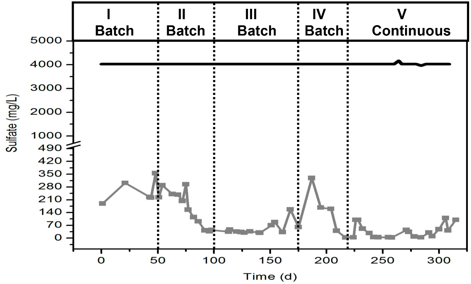
A typical behavior of the sulfate reduction in the bioreactor is shown in Figure 5. It is important to notice that during the first weeks of operation sulfate reduction will be slow. However slow, the consumption of over 90% of sulfate over time indicates that the inoculum is developing a microbial community capable of reducing sulfate and therefore, enriched in sulfate reducing bacteria. The different periods in the figure indicate that sulfate reduction was increasing its rate over time. At the beginni...
Dyskusje
There are several applications of sulfidogenesis in environmental biotechnology, one of the most used applications of the metabolism of sulfate reducing bacteria in consortia with fermenting bacteria is in wastewater treatment. UASB reactors are among the main engineered approaches to industrial wastewater treatment with high sulfate concentrations. In this work, we present a protocol to obtain sulfidogenic sludge from marine sediments in a UASB reactor. The critical steps within the protocol to obtain a sulfidogenic slu...
Ujawnienia
The authors Selene Montserrat García-Solares, Claudio Garibay-Orijel and Claudia Guerrero Barajas submitted (as inventors) in 2012 the application to obtain a patent entitled: “Process for the anaerobic treatment of industrial wastewater with high content of sulfate and chlorinated compounds”. This submission has been approved to the stage of the formatting. The submission has Instituto Politécnico Nacional as the rights owner.
Podziękowania
The authors are grateful for the financial support provided by Instituto Politécnico Nacional grants 20120110, 20130399 and 20140239 SIP and also by Instituto de Ciencia y Tecnología del Distrito Federal Mexico (PICS 08-79, ICYT-DF, 2009-2012). Thanks also to CONACYT – Mexico for the graduate scholarship (225806) awarded to Selene Montserrat García-Solares and for the financial support provided by grant 82627.
Materiały
| Name | Company | Catalog Number | Comments |
| trichloroethylene | sigma Aldrich | 251402 | |
| cis-1,2-dichlorotehylene | sigma Aldrich | ||
| trans-1,2-dichloroethylene | sigma Aldrich | D-62209 | |
| vinyl chloride scotty standard | supelco | 1,000 ppm v/v in nitrogen | |
| ethene scotty standard | supelco | 99% purity | |
| pump | Masterflex | Model 7553-75 | |
| spectrophotometer | any | ||
| microcentrifuge | any | ||
| gas tight syringes | any | 100 and 200 microliters | |
| UASB glass reactor | any | under design | |
| gas chromatograph | any | FID detector | |
| capillary column SPB-624 | supelco | ||
| pH meter | any | ||
| viton tubing | Masterflex | ||
| basal medium reagents | any | ||
| trace metals reagents | any | ||
| vitamins solution reagents | any | ||
| sodium sulfate | any | ||
| volatile fatty acids | any | ||
| COD determination kit | HACH | range 0-15,000 mg/L | |
| TOPO-TA cloning kit pCR®4.0 | Invitrogen, US | ||
| S.N.A.P. TM Miniprep Kit | Invitrogen, UK | ||
| Pure link TM Quick Plasmid Miniprep kit | Invitrogen |
Odniesienia
- Lens, P., Esposito, M. V. G., Zandvoort, M. Perspectives of sulfate reducing bioreactors in environmental biotechnology. ReViews Environmental Science and Biotechnology. 1 (4), 311-325 (2002).
- Omil, F., Lens, P., Hulshoff, P., Lettinga, G. Characterization of biomass from a sulfidogenic, volatile fatty acid-degrading granular sludge reactor. Enzyme and MicrobialTechnology. 20, 229-236 (1997).
- Lopes, S. I. C., Wang, X., Capela, M. I., Lens, P. N. L. Sulfate reduction during the acidification of sucrose at pH 5 under thermophilic (55 °C) conditions.II: Effect of sulfide and COD/SO4-2 ratio. Bioresource Technology. 101, 4278-4284 (2010).
- Alfonso, P., Prol-Ledesma, R. M., Canet, C., Melgarejo, J. C., Fallick, A. E. Sulfur isotope geochemistry of the submarine hydrothermal coastal vents of Punta Mita, Mexico. Journal of Geochemical Exploration. 78-79, 301-304 (2003).
- Valdemarsen, T., Kristensen, E. Degradation of dissolved organic monomers and short chain fatty acids in sandy marine sediment by fermentation and sulfate reduction. Geochimica et Cosmochimica Acta. 74, 1593-1605 (2010).
- Quistad, S. D., Valentine, D. L. Anaerobic propane oxidation in marine hydrocarbon seep sediments. Geochimica et Cosmochimica Acta. 75, 2159-2169 (2011).
- Futagami, T., Morono, Y., Terada, T., Kaksonen, A. H., Inagaki, F. Dehalogenation activities and distribution of reductive dehalogenase homologous genes in marine subsurface sediments. Applied and Environmental Microbiology. 75 (21), 6905-6909 (2009).
- U.S. Environmental Protection Agency. List of priority pollutants. Clean Water Methods. , (2014).
- Ozdemir, C., Dursun, S., Karatas, M., Sen, N., Sahinkaya, S. Removal of trichloroethylene (TCE) in upFlow anaerobic sludge blanket reactors (UASB). Biotechnology and Biotechnological Equipment. 21 (1), 107-112 (2007).
- Zhang, Y., Wang, X., Hu, M., Li, P. Effect of hydraulic retention time (HRT) on the biodegradation of trichloroethylene wastewater and anaerobic bacterial community in the UASB reactor. Applied Microbiology and Biotechnology. 99, 1977-1987 (2015).
- . . Standard Methods for the Examination of Water and Wastewater. , (1998).
- Guerrero-Barajas, C., et al. Enhanced sulfate reduction and trichloroethylene (TCE) biodegradation in a UASB reactor operated with sludge developed from hydrothermal vents sediments: process and microbial ecology. International Biodeterioration and Biodegradation. 94, 182-191 (2014).
- Trüper, H. G., Schlegel, H. G. Sulphur metabolism in Thiorhodaceae I. Quantitative measurements on growing cells of Chromatium okenii. Antoine van Leeuwenhoek. 30, 225-238 (1964).
- Gallegos-García, M. G. . Biological processes of sulfate reduction in biofilms for metals precipitation [Ph D thesis]. , (2009).
- Guerrero-Barajas, C., Garibay-Orijel, C., Rosas-Rocha, L. E. Sulfate reduction and trichloroethylene biodegradation by a marine microbial community from hydrothermal vents sediments. International Biodeterioration and Biodegradation. 65, 116-123 (2011).
Przedruki i uprawnienia
Zapytaj o uprawnienia na użycie tekstu lub obrazów z tego artykułu JoVE
Zapytaj o uprawnieniaThis article has been published
Video Coming Soon
Copyright © 2025 MyJoVE Corporation. Wszelkie prawa zastrzeżone