A subscription to JoVE is required to view this content. Sign in or start your free trial.
Methods Article
Operation of the Collaborative Composite Manufacturing (CCM) System
In This Article
Summary
A collaborative composite manufacturing system is developed for robotic lay-up of composite laminates using the prepreg tape. The proposed system allows the production of composite laminates with high levels of geometrical complexity. The issues in the path planning, coordination of the robots and control are addressed in the proposed method.
Abstract
The automated tape placement and the automated fiber placement (AFP) machines provide a safer working environment and reduce the labor intensity of workers than the traditional manual fiber placement does. Thus, the production accuracy, repeatability and efficiency of composite manufacturing are significantly improved. However, the current AFP systems can only produce the composite components with large open surface or simple revolution parts, which cannot meet the growing interest in small complex or closed structures from industry.
In this research, by employing a 1-degree of freedom (DoF) rotational stage, a 6-RSS parallel robot, and a 6-DoF serial robot, the dexterity of the AFP system can be significantly improved for manufacturing complex composite parts. The rotational stage mounted on the parallel robot is utilized to hold the mandrel and the serial robot carries the placement head to mimic two human hands that have enough dexterity to lay the fiber to the mandrel with complex contour.
Although the CCM system increases the flexibility of composite manufacturing, it is quite time-consuming or even impossible to generate the feasible off-line path, which ensures uniform lay-up of subsequent fibers considering the constraints like singularities, collisions between the fiber placement head and mandrel, smooth fiber direction change and keeping the fiber placement head along the norm of the part's surface, etc. Moreover, due to the existing positioning error of the robots, the on-line path correction is needed. Therefore, the on-line pose correction algorithm is proposed to correct the paths of both parallel and serial robots, and to keep the relative path between the two robots unchanged through the visual feedback when the constraint or singularity problems in the off-line path planning occur. The experimental results demonstrate the designed CCM system can fulfill the movement needed for manufacturing a composite structure with Y-shape.
Introduction
Recently, the increasing need for high performance composite structures in various industries has greatly driven the development of the composite manufacturing technologies1,2. The traditional manual production cannot meet the high efficiency, accuracy and quality requirement of emerging industry. This aspect has encouraged the development of new production technologies such as AFP systems. The AFP technology automates the production of composite material structures using prepregs, which are present in the form of strips composed of impregnated fiber tapes (glass, carbon, etc.) of semi-polymerized resin. In the AFP system, a deposition head with the ability of heating and compacting the resin prepregs is mounted on a fiber placement machine or an industrial robot. The fiber placement machine or robot carrying the deposition head lays up the prepregs traversing the surface of the tooling mandrels. In the process of manufacturing, the tooling mandrel is used as a mold to be wound around by the prepregs to form a certain structure of composite part. The mandrel will be removed after the part is cured. The current AFP systems can significantly improve the efficiency and quality of the production of composite materials3,4,5. However, they are limited to the production of the open surfaces presenting a flat or contoured surface, or simple revolution parts such as cylinders or cones due to the insufficient DoF of the system and the difficulties in generating trajectories. Especially, the aerospace industry and the production industries of sports equipment are now interested in this technique for the production of structures with more complex geometries, like "Y" tubes or the structures forming closed-loops such as bicycle frames.
To be able to manufacture the structures with complex geometries, the flexibility of the AFP system should be improved. For example, an 8 DoF AFP system has been proposed6 by adding a linear track to a 6 DoF industrial robot and a rotational stage to the mandrel holding platform. However, the system is still not suitable for manufacturing the above-mentioned parts with complex geometries. The collaborative robotic system consisting of two robots is a promising solution to increase the dexterity by employing one robot to hold the fiber placement head at the end-effector and another robot to hold the mandrel. The two-serial-robot collaborative system may not solve the fiber placement problem, since the serial robots tend to deform and lose the accuracy due to its cantilever structure, considering the weight of the mandrel and the compaction force7. Compared with the serial robots, 6 DoF parallel robots, which have been utilized in the flight simulator and medical tools, enjoy better stiffness and accuracy8. Therefore, a parallel-serial collaborative robot system, in additional to a rotational stage mounted on the platform of the parallel robot, is built for handling the complex structures manufacturing in this paper.
However, the built collaborative robotic system yields difficulties in designing the controller for each robot to meet the high accuracy requirement of fiber placement. The accurate position measurement of the end-effector could be achieved by using laser tracking system, which is commonly used to guide the industrial robot in various aerospace drilling applications9,10. Although the laser tracking system can provide high accurate position measurement, the main drawbacks lie in the cost of the system and the occlusion issue. The laser tracking system is expensive, e.g., a commercial laser tracker and its accessories cost up to US$90,000, and the laser beam is easily occluded during the movement of the robots. Another promising solution is the vision measurement system, which can provide 6D pose measurement of the end-effector with a considerable accuracy at a low cost. The pose is referred to as the combination of the 3D position and 3D orientation of the end-effector with respect to the base frame of the robot. The optical CMM (see Table of Materials) is a dual camera-based visual sensor. By observing several reflector targets attached on the end-effectors of the two robots, the relative poses between the robots can be measured in real time. The optical CMM has been successfully applied to the robotic calibration11 and dynamic path tracking12 and thus is introduced to provide the feedback measurement to the closed-loop control systems of the proposed CCM system in this study.
The quality of the end composite product is largely dependent on how the original fiber path is generated for the AFP13,14. The path generation process is normally performed by using off-line programming software. The generated path consists of a series of tag points on the mandrel, which indicate the pose of the fiber placement head. Unlike other trajectory planning applications such as paint deposition, polishing or machining, where different types of coverage paths are possible, the choice is limited in the case of AFP, since the fiber is continuous and it is not possible to perform abrupt changes in direction (sharp corners) without damaging it and the placement head should be kept in the norm of the surface of the parts. The first development of trajectory generation technique for AFP has been concentrated on manufacturing large flat panels5 before moving towards the manufacturing the objects of 3D shapes such as open curved surfaces or cones5,14. But, no practical methodology has been developed for generating off-line path for the parts with complex geometries such as Y-shape or the other shapes. Therefore, an effective path planning algorithm for the parts with complex-contoured surfaces is designed to ensure uniform lay-up of subsequent fibers without gaps or overlaps in our previous research15. Considering the practicality and the effectiveness of the path generating algorithm, only the 6-DoF serial robot with the placement head and 1-DoF rotational stage as the mandrel holder are considered as the target system to find the optimum trajectory planning in joint space with minimum time criteria. It could be too complicated and time-consuming to generate the off-line trajectory for the whole 13 DoF CCM system due to the heavy kinematics calculation and the consideration of various constraints like singularities, collisions, smooth direction changing and keeping the placement head in the norm of the parts surface, etc.
The proposed off-line trajectory planning can generate the servo reference for the 6 DoF serial robot and the rotational stage respectively with exact timing. Even with this off-line trajectory planning, it could be impossible to generate a feasible path under all the constraints for certain geometry parts. Moreover, the positioning errors of the robots may cause the robots to collide with the mandrel or another device in the working environment. The on-line path modification is implemented based on the visual feedback from the optical CMM. Therefore the on-line pose correction algorithm is proposed to correct the path of the parallel robot and to tune a corresponding offset on the path of the serial robot simultaneously through the visual feedback. When the collision and other constraints are detected, the relative pose between the two robots is also kept unchanged while following the off-line generated path. Through the correction of the on-line path, the CCM system can avoid these points smoothly without any termination. Due to the flexibility of the parallel robot, the 6D correction offsets can be generated with respect to different constraints. This manuscript presents a detailed operation procedure of the CCM system using on-line pose correction algorithm.
Protocol
1. Frame Definitions of the CCM system
NOTE: The optical CMM is a dual camera sensor, which can track the object with a rigid set of reflectors as the targets in real time. The placement principle of these targets is that the targets are stuck at the asymmetric locations with certain distance among them. The targets need to be fixed on the robots or the placement head and remain in the field of view (FOV) of the optical CMM. At least four targets should be observed for each defined frame by the optical CMM all the time. The base frame of the parallel robot, the end-effector frame of the parallel robot, and the tool frame of the serial robot are denoted as Fb, FtP, and FtS, respectively. The definitions of those frames are shown in Figure 1. Because the base frames of the parallel robot and the serial robot are fixed, the transformation matrix between the two base frames can be derived by calibration.

Figure 1. Collaborative Composite Manufacturing (CCM) System Setup. The hardware of the CCM system consists of a 6-RSS parallel robot, a 1-DoF rotational stage, a 6-DoF serial robot, a placement head, and the optical CMM. The mandrel is clamped on the rotational stage, and the rotational stage is mounted on the parallel robot. Please click here to view a larger version of this figure.
- Definition of the base frame of the parallel robot
- Load the frame definition file through the software of the optical CMM (see the Table of Materials).
- Click Positioning > Detect Targets. Select the targets that are attached on the motors of the parallel robot. Click Accept to take those targets as the positioning reference of the whole system.
- In the Entities list, click Base Frame and select Make this Reference Frame the Origin.
NOTE: The purpose of Step 1.1 is to take Fb as the reference frame of the whole system. The frame definition file can be obtained at the following link: <https://users.encs.concordia.ca/~wfxie/Jove_program/P3.csf>.
- Definition of the tracking model of the end-effector platform frame
- Select Tracking Models in the navigation area. Click Detect Model, and then select the targets fixed on the end-effector platform of the parallel robot. Click Accept.
- Click the generated detection model. Select Up_Frame in the drop-down list of the Origin Offset. Then click Apply.
NOTE: This step is to set up the fixed relationships between the end-effector platform frame FtP and the targets attached on the end-effector platform. - Click File-Export-Tracking model, and enter a file name to save the tracking model.
- Definition of the tracking model of the tool frame
- Select Tracking Models. Click Detect Model, then select the targets fixed on the tool frame of the serial robot. Click Accept.
- Click the generated detection model. Select SerToolFrame in the drop-down list of the Origin offset. Click Apply and save the defined tracking model.
2. System Preparation
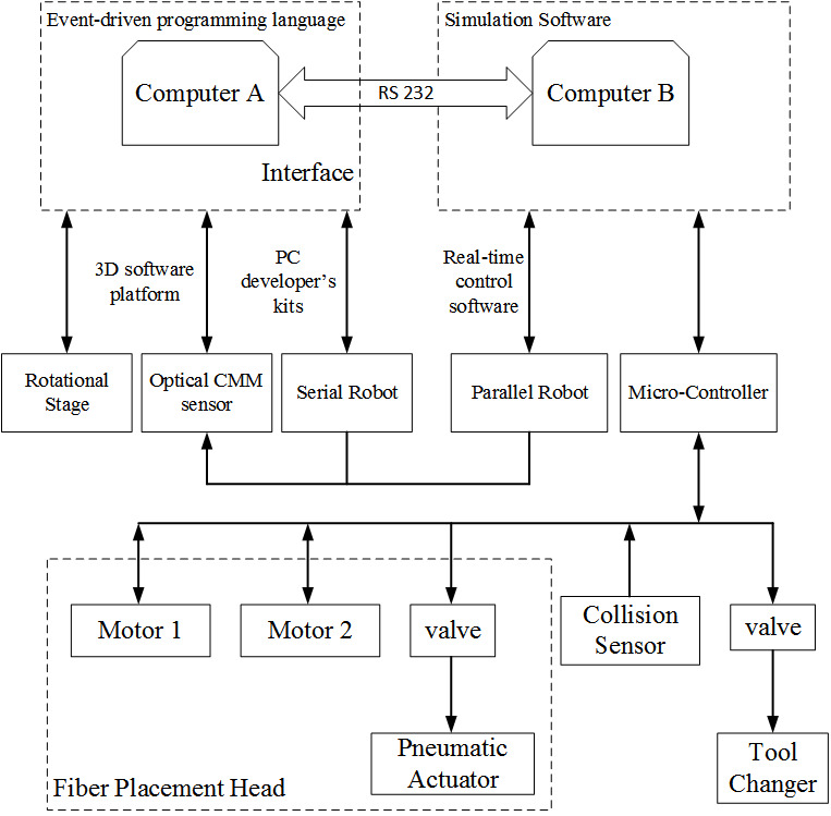
NOTE: The control system layout of the CCM system is shown in Figure 2.

Figure 2. System Layout. Two computers (A & B) are used for controlling the CCM system. The communication between them is via RS232. Computer A controls the rotational state, photogrammetry senor and serial robot. Computer B controls the parallel robot, motors and valves etc. Please click here to view a larger version of this figure.
- Preparation of the rotational stage
- Load the integrated control interface programed by event-driven programming language on computer A.
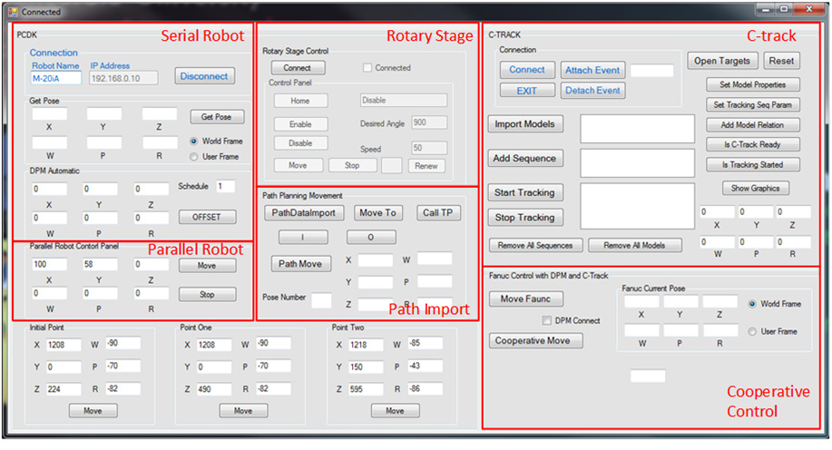
NOTE: The control interface is shown in Figure 3. The interface program can be obtained at the following link: <https://users.encs.concordia.ca/~wfxie/Jove_program/pcdk-ctrack.rar>. - Click Connect to connect the controller of the rotational stage. Click Enable to connect the motor of rotational stage. Then click Home to move the rotational stage to the home position.
- Load the integrated control interface programed by event-driven programming language on computer A.

Figure 3. Control Interface. The control software programmed by event-driven programming language. The interface is composed of 6 sections: serial robot, parallel robot, rotational stage, path import, optical CMM and cooperative control. Please click here to view a larger version of this figure.
- Preparation of the serial robot
- Power on the controller of the serial robot (see the Table of Materials).
- Click Connect on the integrated control interface to connect the robot server.
- Preparation of the Optical CMM
- Power on the controller of the optical CMM and wait until the screen of the controller shows Ready.
- Click Connect on the integrated control interface to connect the optical CMM via Application Programming Interface (API).
- Import the models built in section 1, which includes the Base model, the Upper platform model and the End-effector model of the serial robot.
- Click Add Sequence. Add the relative sequence between the models if it is necessary. Then click Start Tracking to track the pose of the models.
- Preparation of the Parallel robot
- Power on the controller of the parallel robot.
- Load the SerialPort_Receive program and select Normal mode.
NOTE: The SerialPort_Receive program cannot control the parallel robot directly. It is used to receive the remote data from computer A via serial communication port. The SerialPort_Receive program can be obtained at the following link: <https://users.encs.concordia.ca/~wfxie/Jove_program/SerialPort_Receive.mdl>. - Load the ParaRemoteControl program and select External mode. Then click Incremental Build to connect to target.
NOTE: The ParaRemoteControl program is used to receive the desired pose from SerialPort_Receive program and control the parallel robot. The ParaRemoteControl program can be obtained at the following link: <https://users.encs.concordia.ca/~wfxie/Jove_program/ParaRemoteControl.mdl>. - Click Start Simulation of the two programs to initialize the controller of the parallel robot.
3. Generating the off-line path
- Load the path planning interface through the numerical computing software (see the Table of Materials).
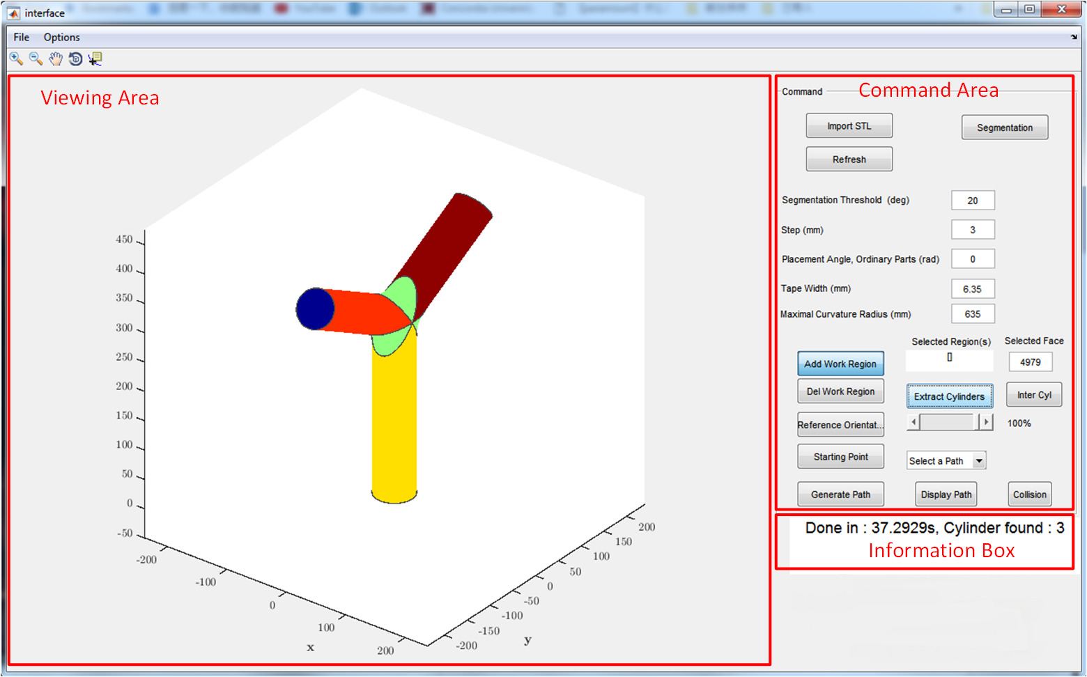
NOTE: The interface is shown in Figure 4. The path planning interface is the off-line software to generate the path for the system and can be obtained at the following link: <https://users.encs.concordia.ca/~wfxie/Jove_program/AFP_PathPlanning_Pcode.zip>.

Figure 4. Path Planning Interface. The path planning software is composed of 3 sections: Visual Area, Command Area and Information Box. The "Viewing Area" section allows the 3D display of the parts to be processed. The "Command Area" section is to perform the main actions for generating the off-line path. The "Information Box" section displays the information about the status of the program. Please click here to view a larger version of this figure.
- Click Import STL and choose the part file. Then click Segmentation.
NOTE: The part is divided into separated regions (cylinders and junctions of Y-shape part). The different regions are displayed in different colors. - Click Add Work Region and select the region on the extraction of cylinders.
- Adjust the slider to 100% and click Extract Cylinders.
- Click Add Work Region to select the starting branch of the path.
- Click Generate Path. Choose the third option: Constant Placement Angle (CPA) in the pop-up dialog window.
- Choose the desired placement angle 90° in the pop-up dialogue window. Then choose the red dot.
- To display the generated path, click Select a Path drop-down menu. Then, select the path.
- To save this path, click File > Save and enter a file name.
4. Individual decomposition of the trajectory for the serial robot and rotational stage
- Run the Methode_Jacobian function in the numerical computing software (see Table of Materials).
NOTE: Methode_Jacobian function is used to decompose the generated path in Step 3 into two individual trajectories for the serial robot and the rotational stage. - Select the desired path file (generated by path planning interface) and click open.
- Enter the desired path number.
- The first point of the trajectory is then calculated. Choose the desired configuration for the manipulator to reach this pose.
NOTE: When Step 4.4 is completed, a graph showing the evolution of joint values is displayed. A file containing the trajectory for the serial robot and the rotational stage is generated.
5. Running the off-line path without the path modification algorithm
- Press Select on the teach pendant and choose the name of the imported file. Press Enter to load the path file.
- Turn the switch of the robot controller to Auto mode. Turn the teach pendant ON/OFF switch to Off.
- Press Cycle Start of the controller of the serial robot to run the path.
- Click Cooperative Move located at the Cooperative Control panel.
NOTE: The system will execute the offline path without the on-line path modification algorithm. If the joint reaches to the singularity or constraint condition, the system will stop.
6. Running the off-line path with the path modification algorithm
- Repeat steps 5.1–5.3. Then click DPM Connect located at the Cooperative Control panel in Figure 3 to add the on-line path modification ability for the system.
- Click Cooperative Move located at the Cooperative Control panel.
NOTE: The system will execute the offline path with the on-line path modification algorithm. During the execution, the singularities and joints’ constraints are monitored through the encoder measurement of the serial robot. The system can smoothly pass the singularity or constraint limitation points without termination.
Results
The experiment aims at demonstrating the process of realizing the motion of laying up the fiber on the Y-shape mandrel of the proposed CCM system. The process is carried out in three steps: path generation; trajectory decomposition; and singularity and constraint avoidance.
Path generation
Normally, the standard orientation is used in industry to define the different plies of the laminate. In this paper, t...
Discussion
The experimental results show the manufacturing process of 90° ply placement angles of the designed CCM system. The methodologies proposed in this paper can be used to lay up the fiber with 0° and 45° ply placement angles on the mandrel with Y-Shape and other shapes. While the built-in controller of the serial robot is able to provide the singularity avoidance feature17, only linear movement of the end-effector is supported. When the end-effector executes the task of the circle move...
Disclosures
The authors have nothing to disclose.
Acknowledgements
This project was funded by the Natural Sciences and Engineering Research Council (NSERC) of Canada Industrial Research Chair in Automated Composites Manufacturing and the Fonds de recherche du Québec – Natrue et technologies (FRQNT).
Materials
| Name | Company | Catalog Number | Comments |
| AeroBasic | Aerotech | Motion control software | |
| Collaborative Composite Manufacturing (CCM) System | Concordia University | A CCM system is proposed to manufacture more complex composite components which pose high demand for trajectory planning than those by the current AFP system. The system consists of a 6 degree-of-freedom (DOF) serial robot holding the fiber placement head, a 6-DOF revolute-spherical-spherical (RSS) parallel robot on which a 1-DOF mandrel holder is installed and an eye-to-hand optical CMM sensor, i.e. C-track, to detect the poses of both end-effectors of parallel robot and serial robot. | |
| C-track | Creaform Inc. | An eye-to-hand optical CMM sensor | |
| Fanuc M-20iA | Fanuc Inc. | Serial robot | |
| Matlab | MathWorks | A multi-paradigm numerical computing software | |
| Quanser | Quanser Inc. | Providing the engineering lab equipments for teaching and research. | |
| VB | Microsoft | Visual Basic | |
| Vxelements | Creaform Inc. | Software for C-track |
References
- Groppe, D. Robots Improve the Quality and Cost-effectiveness of Composite Structures. Industrial Robot: An International Journal. 27 (2), 96-102 (2000).
- Ahrens, M., Mallick, V., Parfrey, K. Robotic Based Thermoplastic Fibre Placement Process. Industrial Robot: An International Journal. 25 (5), 326-330 (1998).
- hirinzadeh, B., Cassidy, G., Oetomo, D., Alici, G., Ang, M. H. Trajectory generation for open-contoured structures in robotic fibre placement. Robotics and Computer-Integrated Manufacturing. 23 (4), 380-394 (2007).
- Shirinzadeh, B., Foong, C. W., Tan, B. H. Robotic fibre placement process planning and control. Assembly Automation. 20 (4), 313-320 (2000).
- Shirinzadeh, B., Alici, G., Foong, C. W., Cassidy, G. Fabrication process of open surfaces by robotic fibre placement. Robotics and Computer Integrated Manufacturing. 20 (1), 17-28 (2004).
- Dasgupta, B., Muthyunjaya, T. S. The Stewart platform manipulator: a review. Mechanism and Machine Theory. 35 (1), 15-40 (2000).
- Zhang, X. M., Xie, W. F., Hoa, S. V., Zeng, R. Design and Analysis of Collaborative Automated Fiber Placement Machine. International Journal of Advanced Robotics and Automation. 1 (1), 1-14 (2016).
- Shirinzadeh, B., et al. Laser interferometry-based guidance methodology for high precision positioning of mechanisms and robots. Robotics Computer-Integrated Manufacturing. 26 (1), 74-82 (2010).
- Vincze, M., Prenninger, J. P., Gander, H. A laser tracking system to measure position and orientation of robot end effectors under motion. International Journal of Robotics Research. 13 (4), 305-314 (1994).
- Li, P., Zeng, R., Xie, W., Zhang, X. Relative posture-based kinematic calibration of a 6-RSS parallel robot by optical coordinate measurement machine. International Journal of Advanced Robotic Systems. 15 (2), (2018).
- Shu, T., Gharaaty, S., Xie, W. F., Joubair, A., Bonev, I. Dynamic path tracking of industrial robots with high accuracy using photogrammetry sensor. IEEE/ASME Transactions on Mechatronics. 23 (3), 1159-1170 (2018).
- Shirinzadeh, B., Cassidy, G., Oetomo, D., Alici, G., Ang, M. H. Trajectory generation for open-contoured structures in robotic fibre placement. Robotics and Computer-Integrated Manufacturing. 23 (4), 380-394 (2007).
- Blom, A. W., Abdalla, M. M., Gürdal, Z. Optimization of course locations in fiber-placed panels for general fiber angle distributions. Composites Science and Technology. 70 (4), 564-570 (2010).
- Hély, C., Birglen, L., Xie, W. F. Feasibility study of robotic fibre placement on intersecting multi-axial revolution surfaces. Robotics and Computer-Integrated Manufacturing. 48, 73-79 (2017).
- Zhang, X. M., Xie, W. F., Hoa, S. V. Semi-offline trajectory synchronized algorithm of the cooperative automated fiber placement system. Robotics and Computer–Integrated Manufacturing. 51, 53-62 (2018).
- Robotics America Corporation. FANUC Robotics SYSTEM R-30iB Handling Tool Setup and Operations Manual. Fanuc. , 1686-1692 (2012).
Reprints and Permissions
Request permission to reuse the text or figures of this JoVE article
Request PermissionExplore More Articles
This article has been published
Video Coming Soon
Copyright © 2025 MyJoVE Corporation. All rights reserved