
Aby wyświetlić tę treść, wymagana jest subskrypcja JoVE. Zaloguj się lub rozpocznij bezpłatny okres próbny.
Method Article
Electrochemically and Bioelectrochemically Induced Ammonium Recovery
W tym Artykule
Podsumowanie
We demonstrate the extraction of ammonium from an ammonium-rich stream using an electrochemical and a bioelectrochemical system. The reactor setup, operation and data analysis are discussed.
Streszczenie
Streams such as urine and manure can contain high levels of ammonium, which could be recovered for reuse in agriculture or chemistry. The extraction of ammonium from an ammonium-rich stream is demonstrated using an electrochemical and a bioelectrochemical system. Both systems are controlled by a potentiostat to either fix the current (for the electrochemical cell) or fix the potential of the working electrode (for the bioelectrochemical cell). In the bioelectrochemical cell, electroactive bacteria catalyze the anodic reaction, whereas in the electrochemical cell the potentiostat applies a higher voltage to produce a current. The current and consequent restoration of the charge balance across the cell allow the transport of cations, such as ammonium, across a cation exchange membrane from the anolyte to the catholyte. The high pH of the catholyte leads to formation of ammonia, which can be stripped from the medium and captured in an acid solution, thus enabling the recovery of a valuable nutrient. The flux of ammonium across the membrane is characterized at different anolyte ammonium concentrations and currents for both the abiotic and biotic reactor systems. Both systems are compared based on current and removal efficiencies for ammonium, as well as the energy input required to drive ammonium transfer across the cation exchange membrane. Finally, a comparative analysis considering key aspects such as reliability, electrode cost, and rate is made.
This video article and protocol provide the necessary information to conduct electrochemical and bioelectrochemical ammonia recovery experiments. The reactor setup for the two cases is explained, as well as the reactor operation. We elaborate on data analysis for both reactor types and on the advantages and disadvantages of bioelectrochemical and electrochemical systems.
Wprowadzenie
Recovery of valuable products from wastewater gains importance as valuable resources become scarce and treatment without recovery represents only a cost. Wastewater contains both energy and nutrients that can be recovered, and nutrient recovery can help to close the production loop1. Recovery of energy through anaerobic digestion is a well-established process, while recovery of nutrients is less common. Recovery of nutrients from liquid waste streams such as urine and manure has been widely investigated, e.g., through the production of struvite and direct stripping of ammonia2,3. However, the need for chemical addition is a downside of these processes4. Here we present a technique for the recovery of cationic nutrients from waste streams, including both potassium and ammonium. The cationic form of these nutrients allows recovery using an ion selective membrane in an electrochemical system. In this case, the electrochemical system consists of an anode chamber (where oxidation takes place), a cathode chamber (where reduction takes place) and an ion selective membrane to separate the compartments. A voltage is applied across the cell to produce a current flow from anode to cathode. This voltage can be generated by an external power source to drive water oxidation and reduction reactions. Alternatively the anodic oxidation, e.g., of organics, can be catalyzed by electroactive bacteria, requiring less power. To close the circuit and maintain the charge balance, a charged species must migrate between the electrodes for each electron generated. Ammonium transport from the anode chamber to the cathode chamber across a cation exchange membrane (CEM) can thus compensate the flux of electrons 4,5.
The technique presented here not only removes ammonium from waste streams, but also enables its recovery. Total ammonia nitrogen (TAN) exists in equilibrium of both ammonium (NH4+) and ammonia (NH3), and is dependent on pH and temperature6. NH4+ is abundantly available due to high TAN concentration and near neutral pH in the anode chamber and this positively charged species can therefore be driven by the current across the CEM into the cathode chamber. The current drives the reduction of water at the cathode, leading to the production of hydroxide ions and hydrogen gas. The TAN equilibrium shifts to nearly 100% NH3 due to the high pH in the cathode chamber (> 10.0). NH3 is a gas that can be easily transferred via air circulation from the stripping unit to the absorption column where it is trapped and concentrated in an acid solution.
This technology has the potential to decrease ammonium toxicity during anaerobic digestion of N-rich streams like manure, thus increasing the energy recovery from these waste streams, while simultaneously recovering nutrients4. Electrochemical and bioelectrochemical extraction of ammonium can also be applied as nutrient recovery technique on waste streams with a high TAN content such as urine thereby avoiding costs for nutrient removal at a WWTP7.
The protocol presented here can serve as a basis for many different electrochemical and bioelectrochemical experiments, as we use a modular reactor. Different electrode types, membranes and frame thicknesses can be combined as explained in the protocol below. The main aim of the protocol is to provide a means for the comparison of electrochemical ammonium recovery and bio-electrochemical ammonium recovery using an electrolysis cell. The systems are evaluated in terms of extraction efficiency, power input and reproducibility.
Access restricted. Please log in or start a trial to view this content.
Protokół
1. Assembling the Reactor and Connecting the Stripping and Absorption Units
- Collect all necessary material to build the reactor: electrodes, frames and rubbers (See List of Materials). Carefully cut all parts to the same dimensions to avoid leaks while assembling the reactor.
- Drill holes in the reactor compartments to fit a male to male connector. Drill one additional hole in the middle of the side of one of the reactor compartments to fit the reference electrode.
- Prepare a stock of 1 M H2SO4 for the absorption column. Increase this concentration as necessary to accommodate higher loads of ammonia.
- Ensure that the membrane is pretreated according to the manufacturer’s instructions. Pretreat the carbon felt electrode by soaking it in 2 mM CTAB (detergent) for 3 min. Rinse the carbon felt with demineralized water8. The stable anode for electrochemical experiments does not require a pretreatment.
- Stack the different reactor parts in order according to the reactor type. For the bioreactor: Perspex endplate, rubber, stainless steel current collector, pretreated graphite felt, Perspex reactor compartment, rubber, cation exchange membrane, rubber, spacer material, stainless steel mesh electrode, rubber, Perspex reactor compartment, rubber, Perspex endplate
- Stack the reactor parts for the electrochemical cell as follows: Perspex endplate, rubber, IrOx anode through the endplate, Perspex reactor compartment, rubber, spacer, rubber, cation exchange membrane, rubber, spacer material, stainless steel mesh electrode, rubber, Perspex reactor compartment, rubber, Perspex endplate.
- Use Teflon to seal the connection ports of the reactor. Place the reference electrode in the same compartment as the working electrode: the anode in the case of a bioelectrochemical cell, the cathode or anode in the case of an electrochemical cell.
- Use nuts and bolts to close the reactor. Tighten bolts on opposite sides to equalize the pressure. Do not use tools to close the reactor as finger-tight is enough to ensure a completely sealed reactor.
- Fill the reactor with water to test if the reactor is leak-free. If leaks appear, check if the bolts are tightened enough or if one of the reactor parts moved while assembling the reactor. If no leaks are detected, empty the water from the reactor.
- Add Raschig rings in both the strip and absorption column to fill the columns halfway.
- Calibrate the flow rate of all the pumps. Connect the feed and recirculation pumps to the reactor and the air pump to the stripping and absorption units (Figure 1). Minimize the length of the tubing as much as possible.
- Fill the absorption column with 250 ml of 1 M H2SO4, it should cover the Raschig rings. Ensure that the air stream mixes the acid well when the pump is switched on. Increase or decrease the volume of acid based on the stripping column design and air pump capacity.

Figure 1. Reactor setup for the bioelectrochemical system enabling ammonium extraction. The system presented here operates in continuous mode. Solid lines represent liquid flow, dotted lines represent gas flow. Please click here to view a larger version of this figure.

Figure 2. Reactor setup for the bioelectrochemical system enabling ammonium extraction. The system presented here operates in continuous mode. Solid lines represent liquid flow, dotted lines represent gas flow. Please click here to view a larger version of this figure.

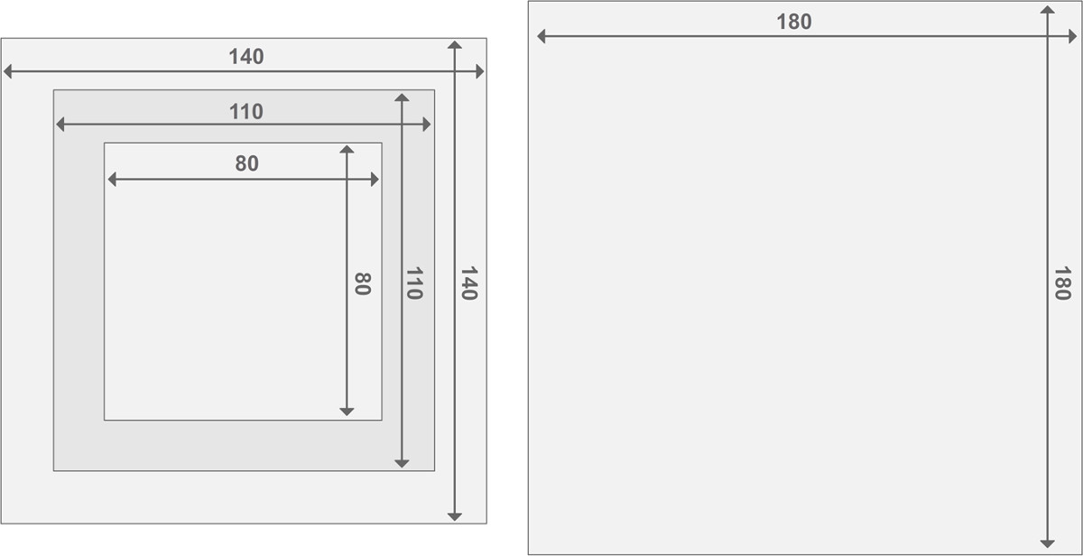
Figure 3. Design of the Perspex reactor frames. Each reactor is comprised of two endplate reactors and 2 reactor compartments. All parts have a thickness of 2 cm. Details concerning the size of other materials can be found in the List of Materials. Please click here to view a larger version of this figure.
2. Bioanode Driven Extraction
- Preparing the media.
- Prepare anolyte for the bioreactor as described in Table 19. Increase the ammonium concentration in the medium to mimic a nitrogen-rich waste stream.
- To store the medium prior to use, autoclave the medium to ensure the carbon source is not depleted through contamination. Prepare vitamins and trace-elements according to Table 1 and add after autoclaving and cooling the medium.
- Flush the medium by purging with nitrogen gas for at least 30 min to remove oxygen. To do this, insert a tube or needle into the medium and turn on the nitrogen gas stream.
- Prepare a conductive solution as catholyte. In this case, use 0.1 M NaCl to allow caustic production.
| Component | Amount | ||
| Na2HPO4 | 6 g/L | ||
| KH2PO4 | 3 g/L | ||
| NaCl | 0.5 g/L | ||
| NH4Cl | 0.5 g/L | ||
| MgSO4·7H2O | 0.1 g/L | ||
| CaCl2·2H2O solution (14.6 g/L) | 1 ml | ||
| Sodium Acetate | 2 g/L (for start-up) | ||
| Trace Elements | 1 ml | ||
| Vitamin solution | 1 ml | ||
| Trace Elements (1,000x) | g/L | Vitamins (1,000x) | g/L |
| CoCl2 | 0.1 | biotin | 0.004 |
| Na2MoO4.2H2O | 0.01 | folic acid | 0.004 |
| H3BO3 | 0.01 | pyridoxine hydrochloride | 0.02 |
| Mg2Cl2.6H2O | 3 | riboflavin | 0.01 |
| ZnCl2 | 0.1 | thiamine hydrochloride | 0.01 |
| CaCl2.2H2O | 0.1 | nicotinic acid | 0.01 |
| NaCl | 1 | DL-calcium pantothenate | 0.01 |
| nitrilotriacetic acid | 1.5 | Vit B12 | 0.0002 |
| AlCl3.6H2O | 0.01 | p-aminobenzoic acid | 0.01 |
| CuCl2 | 0.01 | lipoic(thioctic) acid | 0.01 |
| FeCl2 | 0.1 | myo-inositol | 0.01 |
| MnCl2.2H2O | 0.5 | choline chloride | 0.01 |
| Adjust to pH 6.5 using KOH | niacinamide | 0.01 | |
| pyridoxal hydrochloride | 0.01 | ||
| sodium ascorbate | 0.01 |
Table 1. Anolyte composition for bio-anode driven ammonium extraction.
- Inoculation of the bioreactor
NOTE: Working in sterile conditions is not necessary for this bioreactor, as a mixed culture inoculum is used and reactor conditions will select for the specific electroactive organisms.- Prepare the inoculum. For this bioreactor, prepare a 30 ml mixture of effluents from active anaerobic bioreactors including a fermenter, a bioanode, an anaerobic digester and/or raw wastewater. Collect the mixture in a syringe.
- Connect a gas bag filled with N2 to the anolyte bottle in order to keep the pressure stable while not allowing oxygen to enter. Mix the inoculum source with a volume of anolyte (here, 100 ml of anolyte for 30 ml of inoculum source) by emptying the syringe with inoculum into the medium bottle. Be sure to obtain the volume necessary to fill the anode compartment.
- Using a syringe, fill the anode and cathode compartment simultaneously with their respective solutions. Connect a gas bag filled with N2 to the anolyte bottle so that the anolyte solution can be removed through a sampling port without introducing oxygen. Close the sample port with a tap between transfers.
NOTE: Perform this step together with a colleague to ensure that both reactor compartments are filled simultaneously. - When both reactor compartments are filled, turn on the recirculation pump at a recirculation rate of approximately 6 L/hr.
- Connect the potentiostat cable with the three electrodes, using the anode as working electrode. Position the reference electrode in the anode compartment.
- Switch on the potentiostat in chronoamperometry mode using the potentiostat software. Select a fixed anode potential of -200 mV vs. Ag/AgCl.
- Running a continuous reactor for ammonium extraction
NOTE: As the biofilm develops, current will be produced with the consumption of acetate. As a consequence of acetate depletion, the current will drop (see Results section, Figure 3).- To change to continuous feeding, switch on the feed pump for the anode and cathode. The pump speed will determine the hydraulic residence time (HRT). Here, operate the reactor at a HRT of 6 hr.
- Switch on the air pump of the strip and absorption unit. Recirculate the air in a closed loop, or circulate in an open loop using the ambient air. Air flow configuration can affect absorption efficiencies.
- Refresh the medium three times per week. Prepare fresh anolyte and catholyte as described in the steps 2.1.1-2.1.4.
- After these steps, attach a gas bag filled with N2 to the closed feed bottle, stop the feed pump, put a clamp on the influent line, switch the old and new bottles and finally remove the clamps and restart the pump.
- Each time the feed is refreshed, take 5 ml liquid samples of the effluent and influent of the anolyte and catholyte for measurement of conductivity, pH, acetate content and ammonium concentration.
- When changing the feed, also take a 3 ml sample of the absorption column to monitor the pH and for TAN analysis. When the pH approaches 4, replace the absorbent with fresh 1 M sulfuric acid solution to ensure high absorption efficiency.
- As the current will first increase and then reach a plateau, measure the acetate content in the anolyte influent and effluent to ensure this is not caused by carbon limitation: acetate concentrations in the anolyte effluent below 100 mg/L indicate carbon limitation. Increase the acetate concentration in the feed in that case (Table 2).
- If the current stabilization is not caused by acetate limitations, gradually increase the ammonium concentration in the feed, and wait for stabilization of the current in order to assess extraction efficiencies (Table 3).
NOTE: As the ammonium concentration is increased, ammonia toxicity and high conductivity will challenge the biofilm and the current will eventually drop as a consequence.
| Time | Amount of sodium acetate added to the anode feed (g/L) |
| Day 0 – Day 35 | 2 |
| Day 35 – Day 37 | 3 |
| Day 37 – Day 51 | 4 |
| Day 51 – Day 61 | 5 |
Table 2. Concentration of sodium acetate in the anolyte for the bioanode driven ammonium extraction.
| Time | Amount of NH4HCO3 added to the anode feed (g/L) | Phase |
| Day 0 – Day 16 | 2.26 | I |
| Day 16 – Day 26 | 4.5 | II |
| Day 26 – Day 33 | 9 | III |
| Day 33 – Day 40 | 14.1 | IV |
| Day 40 – Day 47 | 20 | V |
| Day 47 – Day 54 | 25.4 | VI |
| Day 54 – Day 63 | 31 | VII |
Table 3. Concentration of ammonium in the anolyte for the bioanode driven ammonium extraction. The phases are indicated on the current density graph (Figure 2).
3. Electrochemical Extraction
- Preparing the media
- Prepare a synthetic wastewater stream as anolyte according to Table 44. Add ammonium sulfate to reach a final concentration of 1, 3, or 5 g N/L.
- Prepare a 0.1 M NaCl solution for the catholyte.
| Component | Amount |
| Na2HPO4.2H2O | 1.03 g/L |
| KH2PO4 | 0.58 g/L |
| MgSO4·7H2O | 0.1 g/L |
| CaCl2.2H2O | 0.02 g/L |
| (NH4)2SO4 | depending on the experiment, to obtain 1/3/5 g N/L final concentration |
Table 4. Anolyte composition for electrochemical ammonium extraction4.
- Running a continuous reactor for ammonium extraction
- Switch on the feed pump to fill the reactor compartments. To speed up the process temporarily increase the pump rate.
- Reduce the pump speed to obtain an HRT of 6 hr once the reactor is filled. Switch on the recirculation pump at a rate of 6 L/hr. Take a sample of the influent (5 ml).
NOTE: Measure the flow rate periodically throughout the experiment to ensure it does not vary. - Start the strip and absorption unit. Operation of this unit is the same as for the bioreactor.
- Switch on the potentiostat in chronopotentiometry mode using the potentiostat software. First apply a low current density of about 0.5 A/m² to polarize the membrane and to determine nitrogen flux due to diffusion alone.
- When the system has been polarized for 24 hr, apply the current density necessary for the experiment. Test different current densities, usually ranging from 10 A/m² to 50 A/m². Take samples of the anode and cathode effluents, and the absorption column before increasing the current density.
NOTE: After 3 HRT cycles, the reactor should approach steady state. - Once the reactor has reached steady state, take at least 3 samples over a time course. Take samples from the anode and cathode effluents, and the absorption column (5 ml each). Write down the sampling volume, date and time.
- Depending on the stability of the anode influent, take a new anode influent sample if necessary. This is necessary when real wastewater is used.
- Change the test conditions, such as applied current density and TAN concentration. After each change, let the reactor stabilize for at least 3 HRTs before taking samples.
- When the pH of the absorption column approaches 4, replace the absorbent with fresh 1 M sulfuric acid solution.
4. Sample Analysis
- Measure the pH and the conductivity of the samples the same day as sampling to reduce inaccuracies due to loss of volatile ammonia. Measure pH and conductivity using adequately calibrated pH and conductivity probes.
- If the sample are not measured immediately, store samples for TAN analysis (both reactors) and fatty acid analysis (bioreactor) at 4 °C. Filter samples from the bioreactor anode effluent and influent through 0.45 μm filters to remove biomass and help preserve fatty acids. Fill all sample tubes to the rim in order to minimize NH3 loss.
- Measure nitrogen as TAN by the standard steam distillation method or any other reliable method for measuring TAN10.
- Measure fatty acids as acetate by any reliable method, such as ion chromatography or gas chromatography11.
5. Data Analysis and Calculations
- Export the potentiostat data file from the software and import it to a spreadsheet program. Calculate averages per hour for the electrochemical variables to decrease the number of data points and smooth the curves when plotting them.
- Collect all measured data (pH, ammonium, VFA) in one data file for calculations. The calculations are discussed in the results section.
- Calculate the current production by the bioreactor. This is best represented as current density, which is calculated as follows (Equation 1,12):
 Equation 1
with j as the current density, I the absolute current, and A the projected surface area of the electrode. In certain software it is possible to have this calculated automatically by entering the anode surface area before the start of the experiment. - Calculate the parameters related to ammonium extraction
- Calculate the nitrogen flux. Normalize nitrogen flux (g N/m²/d) to the membrane surface area then expressed as a current density (IN). Use this value to calculate the CE (Equation 2, 3, and 4):
 Equation 2
where CAn,in (g N/L) and CAn,out (g N/L) are the measured ammonium concentrations coming in and out the anode compartment, respectively. Q (L/d) is the anode flow rate and A (m2) is the membrane surface area (equal to projected anode and cathode surface area). - Present the nitrogen flux as current density (IN, A/m²):
 Equation 3
where zNH4+ (-) is the charge of NH4+, F the Faraday constant (96,485 C/mol) and M the molecular weight of nitrogen (14 g/mol). - Calculate the current efficiency (CE, %) as:
 Equation 4
where IApplied (A/m²) is the applied (electrochemical extraction) or measured (bioelectrochemical extraction) current density. - Calculate the theoretical nitrogen flux. Calculate the maximum theoretical nitrogen flux (JN,Max, g N/m²/d) for a given applied current and membrane surface area (Equation 5) as:
 Equation 5
 - Calculate the nitrogen removal efficiency (RE, %). Refer to the percentage of ammonium that is removed from the anolyte as the removal efficiency. Calculate from the anode influent and effluent TAN concentrations (Equation 6).
 Equation 6
 - Calculate the maximum theoretical nitrogen removal efficiency (REmax, %) for a given influent TAN load and applied current (Equation 7):
 Equation 7
where JN,applied (g N m−2 d−1) is the applied current density expressed as a nitrogen flux.
- Calculate the nitrogen flux. Normalize nitrogen flux (g N/m²/d) to the membrane surface area then expressed as a current density (IN). Use this value to calculate the CE (Equation 2, 3, and 4):
- Calculate gas/liquid ratio as (Equation 8):
 Equation 8
 - Calculate the maximal capacity of the absorption column. Calculate the maximum theoretical N load to the absorption column from the maximum theoretical nitrogen flux JNmax, the TAN concentration in the influent (mol/L), the time of operation t, the membrane surface area A, and the volume of absorbent V (Equation 9):
 Equation 9
 - Calculate the stripping efficiency SE (%) (Equation 10):
 Equation 10
 - Calculate the energy input for ammonium extraction through the cation exchange membrane (EN, expressed as kWh/kg N) (Equation 11):
 Equation 11
With ΔV the measured potential difference between anode and cathode. In the case of the bioreactor, ΔV was calculated as the average for the sampling period, for the electrochemical reactor the average for the entire run is taken.
Access restricted. Please log in or start a trial to view this content.
Wyniki
Chronoamperometry results from the bioreactor
The chronoamperometry results, calculated according to Equation 1, show a typical graph for a continuous reactor (Figure 4). At the start of the experiment, the anode and cathode were operated in recirculation mode. This allows a biofilm to develop and the onset of the current production. After 5 days of operation, the current density reached a maximum, followed by a decrease in current production. This is an indic...
Access restricted. Please log in or start a trial to view this content.
Dyskusje
This manuscript provides the necessary tools to set up a bioelectrochemical and an electrochemical cell for ammonium recovery. The calculations presented in the results section provide the parameters for evaluation of the system performance. The biological and electrochemical systems are similar in setup and function. The main difference between the two systems is the choice of a fixed current for the electrochemical cell versus a fixed anode potential for the bioelectrochemical setup. The fixed current for the abiotic s...
Access restricted. Please log in or start a trial to view this content.
Ujawnienia
The authors have nothing to disclose.
Podziękowania
This work was supported by the BOF grant for SG from Ghent University. AL is supported by the Rutgers University NSF Fuels-IGERT. SA is supported by the European Union Framework Programme 7 project “ProEthanol 2G.” SA and KR are supported by Ghent University Multidisciplinary Research Partnership (MRP)—Biotechnology for a sustainable economy (01 MRA 510W). JD is supported by an IOF Advanced grant (F2012/IOF-Advanced/094). KR is supported by by the ERC Starter Grant “Electrotalk”. The authors thank Tim Lacoere for designing the TOC art figure, Robin Declerck for building the strip and absorption columns and Kun Guo for providing the inoculum source.
Access restricted. Please log in or start a trial to view this content.
Materiały
| Name | Company | Catalog Number | Comments |
| Carbon Felt 3.18 mm Thick | Alfa Aesar | ALFA43199 | Used as bioanode, 110 mm x 110 mm |
| Ti electrode coated with Ir MMO | Magneto Special Anodes (The Netherlands) | Used as stable anode for electrochemical tests | |
| Stainless steel mesh | Solana (Belgium) | RVS 554/64: material AISI 316L, mesh width: 564 micron, wire thickness: 140 micron, mesh number: 36,6 | Used as cathode, 110 mm x 110 mm |
| Stainless steel plate | Solana (Belgium) | inox 304 sheet, thickness: 0.5 mm | Used as current collector for the bioanode |
| Ag/AgCl Reference Electrode | Bio-Logic (France) | A-012167 RE-1B | |
| Potentiostat (VSP Multipotentiostat) | Bio-Logic (France) | ||
| EC Lab | Bio-Logic (France) | software for performing electrochemistry measurements | |
| Cation Exchange Membrane | Membranes International (USA) | Ultrex CMI-7000 | Pretreated according to the manufacturers' instructions |
| Turbulence Promotor mesh | ElectroCell Europe A/S (Tarm, Denmark) | EPC20432-PP-2 | spacer material, 110 mm x 110 mm |
| Connectors | Serto | 1,281,161,120 | Other sizes possible, dependant on tubing type and size of holes in frames |
| Strip and absorption column | In house design | ||
| Tubing | Masterflex | HV-06404-16 | |
| Gas bag | Keika Ventures | Kynar gas bag with Roberts valve | |
| Rashig Rings | Glasatelier Saillart (Belgium) | Raschig rings 4 x 4 mm | Put inside the strip and absorption column to improve the air/liquid contact. Available with many suppliers |
| Rubber sheet | Cut to fit on the perspex frames | ||
| Perspex reactor frames | Vlaeminck, Beernem | In-house design, see tab "reactor frames" in this file |
Odniesienia
- Verstraete, W., Van de Caveye, P., Diamantis, V. Maximum use of resources present in domestic "used water". Bioresource Technology. 100 (23), 5537-5545 (2009).
- Lei, X., Sugiura, N., Feng, C., Maekawa, T. Pretreatment of anaerobic digestion effluent with ammonia stripping and biogas purification. Journal of Hazardous Materials. 145 (3), 391-397 (2007).
- Siegrist, H. Nitrogen removal from digester supernatant-comparison of chemical and biological methods. Water Science and Technology. 34 (1), 399-406 (1996).
- Desloover, J., Abate Woldeyohannis, A., Verstraete, W., Boon, N., Rabaey, K. Electrochemical Resource Recovery from Digestate to Prevent Ammonia Toxicity during Anaerobic Digestion. Environmental Science & Technology. 46 (21), 12209-12216 (2012).
- Kim, J. R., Zuo, Y., Regan, J. M., Logan, B. E. Analysis of ammonia loss mechanisms in microbial fuel cells treating animal wastewater. Biotechnology and Bioengineering. 99 (5), 1120-1127 (2008).
- Emerson, K., Russo, R. C., Lund, R. E., Thurston, R. V. Aqueous ammonia equilibrium calculations: effect of pH and temperature. Journal of the Fisheries Board of Canada. 32 (12), 2379-2383 (1975).
- Kuntke, P., Sleutels, T. H. J. A., Saakes, M., Buisman, C. J. N. Hydrogen production and ammonium recovery from urine by a Microbial Electrolysis Cell. International Journal of Hydrogen Energy. 39 (10), 4771-4778 (2014).
- Guo, K., et al. Surfactant treatment of carbon felt enhances anodic microbial electrocatalysis in bioelectrochemical systems. Electrochemistry Communications. 39, 1-4 (2014).
- Guo, K., Chen, X., Freguia, S., Donose, B. C. Spontaneous modification of carbon surface with neutral red from its diazonium salts for bioelectrochemical systems. Biosensors and Bioelectronics. 47, 184-189 (2013).
- Standard Methods For The Examination Of Water And Wastewater. Rice, E. W., Greenberg, A. E., Clesceri, L. S., Eaton, A. D. , American Public Health Association. (1992).
- Andersen, S. J., et al. Electrolytic Membrane Extraction Enables Production of Fine Chemicals from Biorefinery Sidestreams. Environmental Science & Technology. 48 (12), 7135-7142 (2014).
- Harnisch, F., Rabaey, K. The Diversity of Techniques to Study Electrochemically Active Biofilms Highlights the Need for Standardization. Chemsuschem. 5 (6), 1027-1038 (2012).
- Clauwaert, P., et al. Minimizing losses in bio-electrochemical systems: the road to applications. Applied Microbiology and Biotechnology. 79 (6), 901-913 (2008).
- Atkins, P., De Paula, J. Elements of Physical Chemistry. , Oxford University Press. Oxford, UK. (2012).
- Aelterman, P., Freguia, S., Keller, J., Verstraete, W., Rabaey, K. The anode potential regulates bacterial activity in microbial fuel cells. Applied Microbiology and Biotechnology. 78 (3), 409-418 (2008).
- Kuntke, P., et al. Ammonium recovery and energy production from urine by a microbial fuel cell. Water Research. 46 (8), 2627-2636 (2012).
- Liu, H., Cheng, S., Logan, B. E. Power Generation in Fed-Batch Microbial Fuel Cells as a Function of Ionic Strength. Temperature, and Reactor Configuration. Environmental Science & Technology. 39 (14), 5488-5493 (2005).
- Gimkiewicz, C., Harnisch, F. Waste Water Derived Electroactive Microbial Biofilms: Growth, Maintenance, and Basic Characterization. JoVE. (82), e50800(2013).
- Ping, Q., Cohen, B., Dosoretz, C., He, Z. Long-term investigation of fouling of cation and anion exchange membranes in microbial desalination cells. Desalination. 325, 48-55 (2013).
- Guerin, T., Mondido, M., McClenn, B., Peasley, B. Application of resazurin for estimating abundance of contaminant-degrading micro-organisms. Letters in Applied Microbiology. 32 (5), 340-345 (2001).
Access restricted. Please log in or start a trial to view this content.
Przedruki i uprawnienia
Zapytaj o uprawnienia na użycie tekstu lub obrazów z tego artykułu JoVE
Zapytaj o uprawnieniaThis article has been published
Video Coming Soon
Copyright © 2025 MyJoVE Corporation. Wszelkie prawa zastrzeżone