
A subscription to JoVE is required to view this content. Sign in or start your free trial.
Method Article
Gelatin Methacryloyl Granular Hydrogel Scaffolds: High-throughput Microgel Fabrication, Lyophilization, Chemical Assembly, and 3D Bioprinting
In This Article
Summary
This article describes protocols for high-throughput gelatin methacryloyl microgel fabrication using microfluidic devices, converting microgels to resuspendable powder (micro-aerogels), the chemical assembly of microgels to form granular hydrogel scaffolds, and developing granular hydrogel bioinks with preserved microporosity for 3D bioprinting.
Abstract
The emergence of granular hydrogel scaffolds (GHS), fabricated via assembling hydrogel microparticles (HMPs), has enabled microporous scaffold formation in situ. Unlike conventional bulk hydrogels, interconnected microscale pores in GHS facilitate degradation-independent cell infiltration as well as oxygen, nutrient, and cellular byproduct transfer. Methacryloyl-modified gelatin (GelMA), a (photo)chemically crosslinkable, protein-based biopolymer containing cell adhesive and biodegradable moieties, has widely been used as a cell-responsive/instructive biomaterial. Converting bulk GelMA to GHS may open a plethora of opportunities for tissue engineering and regeneration. In this article, we demonstrate the procedures of high-throughput GelMA microgel fabrication, conversion to resuspendable dry microgels (micro-aerogels), GHS formation via the chemical assembly of microgels, and granular bioink fabrication for extrusion bioprinting. We show how a sequential physicochemical treatment via cooling and photocrosslinking enables the formation of mechanically robust GHS. When light is inaccessible (e.g., during deep tissue injection), individually crosslinked GelMA HMPs may be bioorthogonally assembled via enzymatic crosslinking using transglutaminases. Finally, three-dimensional (3D) bioprinting of microporous GHS at low HMP packing density is demonstrated via the interfacial self-assembly of heterogeneously charged nanoparticles.
Introduction
Assembling HMP building blocks to form tissue engineering scaffolds has gained tremendous attention in the past few years1. GHS, fabricated via HMP assembly, have unique properties compared with their bulk counterparts, including cell-scale microporosity originating from the void spaces among the discrete building blocks. Additional properties, such as injectability, modularity, and decoupled stiffness from porosity, render GHS a promising platform to enhance tissue repair and regeneration2. Different biomaterials have been used for GHS fabrication, including synthetic PEG-based polymers3,4 and polysaccharides, such as alginate5 and hyaluronic acid6,7. Among naturally derived polymers, the most common protein-based biopolymer for GHS fabrication is GelMA8,9,10,11, a crosslinkable, biocompatible, bioadhesive, and biodegradable biomaterial12,13.
HMPs may be fabricated via batch emulsification8, flow-focusing14,15 or step-emulsification9,11 microfluidic devices, blending16, or complex coacervation17,18. Usually, there is a trade-off between the fabrication throughput and HMP monodispersity. For instance, the blending technique yields irregularly shaped and highly polydispersed HMPs. Batch emulsification or complex coacervation enables the production of large volumes of polydispersed spherical HMPs. Flow-focusing microfluidic devices have been used to fabricate highly monodispersed droplets with a coefficient of variation of <5%, however the throughput is significantly low. In step-emulsification microfluidic devices, the highly parallelized steps enable the high-throughput fabrication of monodispersed HMPs19.
Methacryloyl-modified gelatin (GelMA) HMP building blocks are thermoresponsive and (photo)chemically crosslinkable, enabling facile GHS fabrication20. Upon cooling below the upper critical solution temperature (UCST)21 (e.g., at 4 °C), droplets containing a GelMA solution are converted to physically crosslinked HMPs. These HMP building blocks are then packed using external forces (e.g., via centrifugation) to yield jammed microgel suspensions. Interparticle linkages are established between adjacent HMPs via (photo)chemical crosslinking to form mechanically robust GHS14. One of the most important properties of GHS is microporosity, enabling facile cell penetration in vitro11 and enhanced tissue ingrowth in vivo22. Three-dimensional (3D) bioprinting of HMPs is conventionally performed using tightly packed microgel suspensions, compromising microporosity23.
We have recently developed a novel class of granular bioinks based on the interfacial nanoengineering of GelMA microgels via the adsorption of heterogeneously charged nanoparticles, followed by nanoparticle reversible self-assembly. This strategy renders loosely packed microgels shear-yielding and extrusion 3D bioprintable, which preserves the microscale porosity of additively manufactured GHS11. This article presents the methods for high-throughput GelMA droplet fabrication, converting these droplets to physically crosslinked HMPs, fabricating GelMA HMPs using resuspendable powder, GelMA GHS formation, GelMA nanoengineered granular bioink (NGB) preparation, and 3D bioprinting.
Protocol
NOTE: See the Table of Materials for details related to all materials, instruments, and reagents used in this protocol.
1. GelMA synthesis
NOTE: GelMA synthesis should be conducted in a chemical fume hood, and proper personal protective equipment (PPE) should be used all the time.
- Add 200 mL of Dulbecco's phosphate buffered saline (DPBS, 1x) to an Erlenmeyer flask and heat the solution until it reaches 50 °C. Cover the flask with aluminum foil to prevent evaporation.
- Add 20 g of gelatin powder to the DPBS solution at 50 °C while stirring at 240 rpm until the powder is completely dissolved.
- Add 16, 2.5, or 0.5 mL of methacrylate anhydride (MA) to the gelatin solution dropwise via a glass Pasteur pipette to synthesize GelMA with a high, medium, or low degree of methacryloyl substitution, respectively.
CAUTION: MA is a hazardous material. Proper PPE should be used when working with MA. MA is also light-sensitive, so protect the reaction from light by wrapping the flask with aluminum foil. - After 2 h, add 400 mL of DPBS at 50 °C to stop the reaction. Allow stirring to continue at 50 °C for 10 min.
- Pour the solution into a dialysis membrane tubing with 12-14 kDa molecular weight cutoff, and then place the tubing in a 5 L beaker filled with 40 °C ultrapure water. Stir the water at 240 rpm and 40 °C.
- Dialyze the solution against ultrapure water for 10 days and change the water 2x a day to remove unreacted methacrylate anhydride, byproducts, and other impurities.
- After 10 days, add 400 mL of ultrapure water at 40 °C to the GelMA solution. Stir the solution at 240 rpm for 15 min.
- Filter the solution twice using coffee filters, followed by vacuum filtration via a 0.2 µm vacuum filtration unit.
- Pour 25 mL of the filtered solution into 50 mL centrifuge tubes and freeze them at -80 °C, placing the tubes horizontally.
- After 2 days, remove the caps and cover the centrifuge tubes with laboratory wipes. Use tape or a rubber band to hold the wipes tightly.
- Lyophilize the frozen GelMA solution to yield white solid GelMA.
- To conduct proton nuclear magnetic resonance (1H NMR) spectroscopy, separately add 30 mg of gelatin powder (control) or lyophilized GelMA in 1 mL of deuterium oxide (D2O) and maintain the samples at 37 °C until the gelatin powder or GelMA is entirely dissolved.
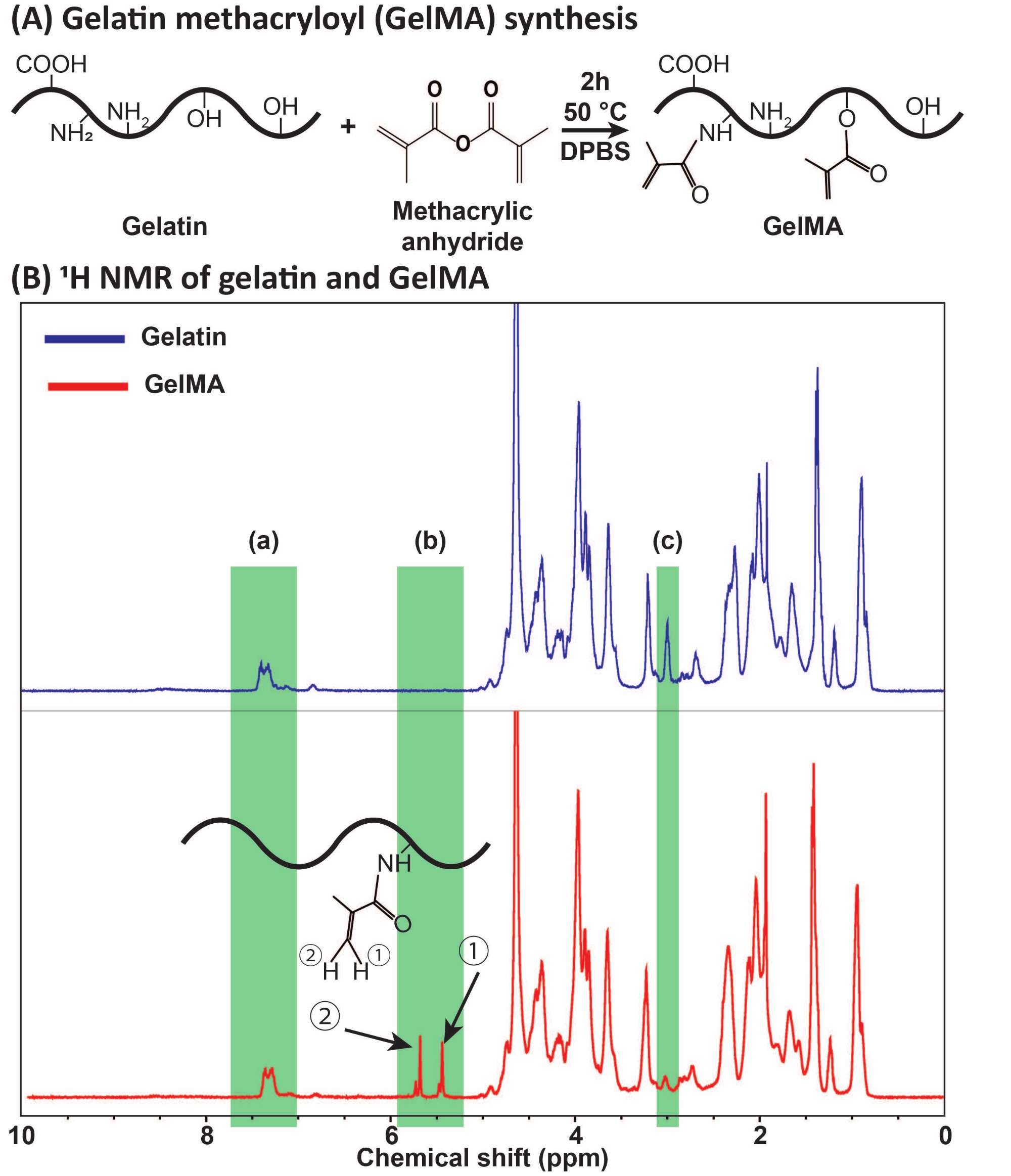
- Obtain the 1H NMR spectra and determine the degree of methacryloyl substitution by integrating the aromatic acids and lysine methylene proton peaks at chemical shifts of ~6.5-7.5 and ~3.0 ppm, respectively. Use the aromatic acids peak as a reference and determine the degree of substitution (DS) using lysine methylene peaks based on equation (1):
DS (%) = [1 - (Area of lysine methylene in GelMA / Area of lysine methylene in gelatin)] × 100 (1)

Figure 1: GelMA synthesis and characterization. (A) GelMA synthesis reaction. Gelatin is modified with methacrylic anhydride at 50 °C for 2 h. (B) The proton nuclear magnetic resonance (1H NMR) spectra of gelatin and GelMA: (a) the peak for aromatic acids, which is selected as the reference for calibration, (b) vinyl functional group peaks after the MA modification of gelatin, and (c) the peak for lysine proteins. In this example, the MA degree of substitution was 71% ± 3% (n = 3). This figure has been modified with permission from Ataie et al.11 Abbreviations: GelMA = gelatin methacryloyl; DPBS = Dulbecco's phosphate-buffered saline; MA = methacryloyl. Please click here to view a larger version of this figure.
2. High-throughput GelMA microgel fabrication
- Device master mold microfabrication
NOTE: Master molds may be microfabricated via soft lithography using the KMPR 1000 negative photoresist series19.- Thaw KMPR 1025 and 1035 overnight. Avoid any light exposure.
- To coat the first layer on the wafer, add KMPR 1025 directly to the middle of the wafer to make an approximately 5 cm circle of photoresist. Run the spin coater at 3,000 rpm for 30 s.
- Soft bake for 12 min on a 100 °C hotplate. Then, cool down on the cooling plate for 5 min.
- Attach the first layer mask to the blank soda lime, then expose the coated wafer to UV light using a mask aligner for 645 mJ/cm2 of dosage.
- Post bake for 3 min on a 100 °C hotplate. Cool down on the cooling plate for 5 min.
NOTE: Do not develop after this step. Develop only once at the end of the process. - Spin coat the second layer on the wafer using the KMPR 1035. Run the spin coater at 1,000 rpm for 30 s.
- Soft bake for 30 min on a 100 °C hotplate. Cool down on the cooling plate for 5 min.
- Attach the second layer mask to the blank soda lime and align the second mask using the aligner through standard alignment signs. Expose to UV light using a mask aligner up to 2,000 mJ/cm2.
- Post bake for 5 min on a 100 °C hotplate.
- Develop for >6 min in the SU-8 developer.
NOTE: If the wafer looks milky, development should be continued for a longer time. Use fresh developer each time and in between for a better outcome. - Spray with isopropanol. Make sure the wafer is clear, with no milky residues. Thoroughly dry the wafer using nitrogen (N2) gas.
- Microfluidic device fabrication
- Pour 50 g of polydimethylsiloxane (PDMS) base part into a transparent plastic cup. Then, add 5 g of the crosslinker to the plastic cup. Mix the base and crosslinker using a spatula vigorously until a creamy texture is obtained.
- Vacuum degas the mixture using a desiccator for 20 min until it becomes clear. Pour the mixture onto the master mold, which is placed inside and taped to a Petri dish.
NOTE: Make sure the thickness (height) of the poured PDMS is ≤8 mm. - Put the Petri dish into the desiccator and vacuum degas the PDMS mixture again for 20 min until all the bubbles are removed. Place the Petri dish in a 70 °C oven for 2 h until the PDMS is crosslinked. Take the Petri dish out of the oven and allow it to cool down.
- Cut the devices out of the mold using a scalpel. Detach the devices slowly from the master mold. Use the biopsy punch (1.5 mm diameter) to cut holes through the inlets and the outlet.
- Remove any dust from the PDMS devices and the glass slides using masking tape, and place the glass slides and the devices in a plasma cleaner chamber. Perform the plasma treatment for 45 s (starting when the chamber turns purple) with air pressure under 400 mTorr. Remove the slides and devices from the chamber, put the device on the glass slides, and apply slight pressure. Put the device in the 70 °C oven for 30 min to enhance the bonding.
- Fill the devices with trichloro(1H,1H,2H,2H-perfluorooctyl)silane (F-silane, 2% v/v) in the engineered fluid to render the channel surface fluorophilic. Inject the F-silane solution through the outlet and make sure all the devices are exposed. Wait for 5-10 min.
NOTE: F-silane should be prepared freshly. In addition, F-silane should not be exposed to air for a long time. - Aspirate the F-silane solution out of the device through the aqueous solution inlet. Wash the device twice using the engineering fluid and aspirate again. Place the device in the 70 °C oven for 30 min to evaporate the remaining oil.
- Droplet formation and GelMA microgel fabrication
- Add 10 mg of lithium phenyl-2,4,6-trimethylbenzoylphosphinate (LAP) to 10 mL of DPBS to prepare a photoinitiator (PI) solution (0.1% w/v). Protect the solution from light by wrapping it in aluminum foil.
- Dissolve the desired amount of GelMA in the PI solution and place it in the 37 °C oven for 1 h until a clear solution is obtained. Protect the solution from light by wrapping in aluminum foil.
- To prepare the oil phase, make a 2% v/v of biocompatible surfactant solution in the engineering fluid.
- Insert the Tygon tubing in the inlets and outlet of the PDMS device. Insert a 25 G blunt needle in the other end of Tygon tubing for inlets. Use the minimum possible tubing length.
- Place the device under the microscope. Keep the environment warm (~40 °C) using a hair dryer and/or a space heater.
- Load the aqueous and oil solutions in separate syringes, connected to the device. Start the syringe pumps with flow rates of 160 and 80 µL/min for the oil (continuous) and aqueous (dispersed) phases, respectively.
NOTE: Start the oil phase first; make sure the oil fills the channel, then start the aqueous phase. - Collect the droplets in a container and evaluate them in the imaging chamber via optical microscopy imaging.
- Place the droplets at 4 °C overnight while protecting them from light to initiate GelMA HMP physical crosslinking and convert the droplets to stable microgels at 4 °C.
3. Converting microgels to resuspendable powder via the microengineered emulsion-to-powder (MEtoP) technology
NOTE: The MEtoP technology to convert the water-in oil emulsion-based HMPs to microparticle powder (micro-aerogels) with preserved properties, such as resuspendability, shape, size, and assembly, has been developed.
- To implement the MEtoP, collect the physically crosslinked HMPs in the engineering fluid using thermally durable microcentrifuge tubes or cryovials. Open the tube caps and seal them with a laboratory wipe and tape.
- Deep-freeze the physically crosslinked HMPs in liquid nitrogen (-196 °C) for 10 min.
- Transfer the flash-frozen tubes to a freeze-dryer instrument. Lyophilize the tubes at low pressure (e.g., 0.06 mbar) for at least 6 h to yield powder.
NOTE: When the lyophilization cycle is finished, break the pressure slowly so the powder is not lost. - Add 1 mL of cooled PI solution (0.1% w/v, 4 °C) to the powder to make microgel suspensions. Vortex for 5 s, then centrifuge at 3,000 × g for 15 s. Discard the supernatant.
- Transfer the packed microgel suspension to a mold using a positive displacement pipette, followed by UV light exposure at 400 nm wavelength with an intensity of 15 mW/cm2 for 60 s to form GHS.

Figure 2: GelMA microparticle powder preparation via MEtoP technology. (A) Images of GelMA powder obtained from the MEtoP technology or conventional lyophilization of HMP. In MEtoP technology or conventional lyophilization, HMPs are suspended in oil-surfactant or aqueous media, respectively. The engineering fluid protects the dispersed phase (HMPs) from aggregation and preserves the physiochemical properties of GelMA microparticles during lyophilization. (B) Schematic illustration of dried HMPs prepared via the MEtoP compared with conventionally lyophilized HMP in an aqueous medium. (C) SEM images of dried GelMA microparticles prepared via the MEtoP compared with conventional lyophilization. Scale bars = 2 mm (left; A), 500 µm (right; A), 10 µm (left; C), and 200 µm (right; C). This figure was modified with permission from Sheikhi et al.26 Abbreviations: GelMA = gelatin methacryloyl; DPBS = Dulbecco's phosphate-buffered saline; MEtoP = microengineered emulsion-to-powder; HMP = hydrogel microparticle; SEM = scanning electron microscopy. Please click here to view a larger version of this figure.
4. GelMA GHS formation
NOTE: This protocol is for preparing 400 µL of microgel suspension. For larger quantities, scale-up is needed. To keep the GelMA HMPs physically crosslinked, all the steps should be performed at about 4 °C by placing the microgel containers in an ice-water bucket.
- Add 400 µL of 1H,1H-perfluoro-1-octanol (PFO) solution in the engineering fluid (20% v/v) to the physically crosslinked GelMA HMPs. Then, vortex for 5 s and centrifuge for 15 s at 300 × g.
NOTE: The PFO solution in the engineering fluid should be prepared freshly and stored in an enclosed container to prevent evaporation. - Remove the oil phase from the GelMA HMPs via pipetting.
- Add 400 µL of PI solution (0.1% w/v) at 4 °C to the microgel suspension. Then, vortex for 5 s and centrifuge at 300 × g for 15 s. Discard the oil afterward.
- Repeat the previous step but centrifuge at 3,000 × g. Remove the supernatant of packed GelMA HMPs via pipetting.
- Transfer the packed GelMA HMPs to a mold using a positive displacement pipette, followed by UV light exposure (wavelength = 400 nm, intensity = 15 mW/cm2, exposure time = 60 s).
5. Nanoengineered granular bioinks (NGB) for the 3D bioprinting of GHS with preserved microporosity
- Add 100 mg of nanoplatelet powder to 3 mL of 4 °C ultrapure water to form a nanoparticle dispersion (3.33% w/v). Vortex the dispersion vigorously inside a 4 °C fridge for 15 min to exfoliate the otherwise aggregated nanoparticles. Properly exfoliated nanoparticles yield a clear dispersion.
- Dissolve 50 mg of LAP in 5 mL of 4 °C ultrapure water to prepare a stock PI solution (1% w/v).
- Add 333 µL of PI solution (1% w/v) to the exfoliated nanoparticle dispersion. Wrap in aluminum foil to protect against ambient light. Vortex for 1 min to mix the nanoparticle dispersion and PI. The final clay and PI concentrations are 3% w/v and 0.1% w/v, respectively.
- Add PFO 20% v/v in engineering fluid (4 °C) to the physically crosslinked GelMA HMPs at a 1:1 volume ratio. Vortex thoroughly for 5 s. Then, centrifuge at 300 × g for 15 s and discard the oil phase containing the surfactant.
- Add the LAP-supplemented nanoparticle dispersion (4 °C) to the washed GelMA HMPs. Vortex for 15 s, centrifuge at 3,000 × g for 15 s, and discard the remaining oil at the bottom as well as the supernatant dispersion.
- Store the suspension at 4 °C while protecting it from light using aluminum foil for 1 day. The product of this step is the GelMA NGB.
- Load the NGB into a 3 mL syringe, seal the loaded syringe with a cap and parafilm, and pulse centrifuge at 200 × g to remove the trapped air. Transfer the bioink to a 3 mL cartridge using a female-female Luer-Lok connector. Centrifuge the cartridge briefly at 200 × g again to remove the trapped air. Keep the NGB at 4 °C in a fridge before using.
- Before cell-laden bioink preparation, prepare a concentrated cell suspension (e.g., NIH/3T3 murine fibroblast cells), containing ~24 million cells in 100 µL of cell culture medium. Load the cell suspension into a 3 mL syringe, couple the NGB-loaded syringe and the cell-loaded syringe using a female-female Luer-Lok connector, and mix the cells and NGB gently by pushing back and forth 40x.
- Print the NGB or cell-laden NGB using a proper bioprinter with a standard conical nozzle. Load the nozzle into the 3 mL printhead. Keep the printing bed temperature below 10 °C. Optimize printing parameters such as speed and back pressure prior to printing.
- Select the substrate and nozzle type (pneumatic 3 mL syringe equipped with standard conical nozzle), calibrate the bioprinter using the device guidelines, select desirable gcode or STL file, and start printing.
NOTE: When performing cell-laden bioprinting, all the materials and devices should be maintained under the biological safety cabinet to minimize contamination. - After the printing, expose the construct to UV light for photocrosslinking (wavelength = 400 nm, intensity = 15 mW/cm2, exposure time = 60 s).

Figure 3: Schematics of GelMA microgel and GHS formation. (A) Schematics of GelMA microgel separation from oil and NGB preparation. PFO (20% v/v in engineering fluid) was added to the GelMA microgel-oil emulsion at a 1:1 volumetric ratio, followed by vortexing and centrifugation at 300 × g for 15 s. To fabricate GelMA GHS, the PI solution (LAP 0.1% w/v in DPBS) was added to the GelMA HMPs, followed by vortexing and centrifugation at 3,000 × g for 15 s. For preparing the NGB, the PI solution (LAP 0.1% w/v in ultrapure water) and nanoplatelet dispersion (3% w/v in ultrapure water) were added to the GelMA HMP suspension, followed by vortexing and centrifugation at 3,000 × g for 15 s. Figure 3A was modified with permission from Ataie, Z. et al.11 (B) Exposing packed GelMA HMPs to light yields GHS. Figure 3B was modified with permission from Sheikhi et al.15 Abbreviations: GelMA = gelatin methacryloyl; GHS = granular hydrogel scaffold; NGB = nanoengineered granular bioink; PFO = 1H,1H-perfluoro-1-octanol; PI = photoinitiator; LAP = lithium phenyl-2,4,6-trimethylbenzoylphosphinate; HMP = hydrogel microparticle; DPBS = Dulbecco's phosphate-buffered saline. Please click here to view a larger version of this figure.
Results
GelMA was synthesized through the reaction of gelatin with MA, as presented in Figure 1A. By tailoring the reaction conditions, such as MA concentration, different degrees of MA substitution were obtained. To quantify the degree of MA substitution, GelMA was assessed via 1H NMR spectroscopy (Figure 1B). Vinyl functional groups with representative peaks at the chemical shifts of ~5-6 ppm confirmed the successful GelMA synthesis from gelatin. ...
Discussion
Gelatin and its derivatives are the most commonly used protein-based biomaterials for HMP fabrication. The challenge of throughput versus particle size monodispersity trade-off can be overcome using step-emulsification microfluidic devices. These devices are capable of forming more than 40 million droplets per hour, with a coefficient of variation less than 5%27. In this article, we discussed the microfabrication of droplets containing GelMA solutions, followed by converting them to GelMA HMPs, po...
Disclosures
The authors declare no conflicts of interest.
Acknowledgements
The authors would like to thank T. Pond, research support specialist at the Department of Chemical Engineering of The Pennsylvania State University (Penn State), the Nanofabrication Lab staff at Penn State, and Dr. J. de Rutte from Partillion Bioscience for the help and discussion regarding nanofabrication processes. A. Sheikhi acknowledges the support of the Materials Research Institute (MRI) and the College of Engineering Materials Matter at the Human Level seed grants, the Convergence Center for Living Multifunctional Material Systems (LiMC2) and the Cluster of Excellence Living, Adaptive and Energy-autonomous Materials Systems (livMatS) Living Multifunctional Materials Collaborative Research Seed Grant Program, and the startup fund from Penn State. Research reported in this publication was partially supported by the National Institute of Biomedical Imaging and Bioengineering (NIBIB) of the National Institutes of Health (NIH) under award number R56EB032672.
Materials
| Name | Company | Catalog Number | Comments |
| 1H,1H-perfluoro-1-octanol | Alfa Aesar, MA, USA | B20156-18 | 98% purity |
| Biopsy punch | Integra Miltex, NY, USA | 33-31A-P/25 | 1.5 mm Biopsy Punch with Plunger System |
| Blunt needle | SANANTS | 30-002-25 | 25 G |
| Bruker Avance NEO 400 MHz | 400 MHz Bruker NEO, MA, USA | NMR device | |
| Centrifuge | Eppendorf, Germany | 5415 C | |
| Centrifuge tube | Celltreat, MA ,USA | 229423 | |
| Coffee filters | BUNN, IL, USA | 20104.0006 | BUNN 8-12 Cup Coffee Filters, 6 each, 100 ct |
| Desiccator | Thermo Scientific | 5311-0250 | Nalgene Vacuum Desiccator, PC Cover and Body, 280 mm OD |
| Deuterium oxide | Sigma, MA, USA | 151882 | |
| Dialysis membrane (12-14 kDa) | Spectrum Laboratories, NJ, USA | 08-667E | |
| Dulbecco's phosphate buffered saline (DPBS, 1x) | Sigma, MA, USA | 56064C-10L | dry powder, without calcium, without magnesium, suitable for cell culture |
| Erlenmeyer flask | Corning, NY, USA | 4980 | Corning PYREX |
| Ethanol | VWR, PA, USA | 89125-188 | Koptec 200 proof |
| External thread cryogenic vials (cryovials) | Corning, NY, USA | 430659 | |
| Freeze dryer | Labconco, MO, USA | 71042000 | Equipped with vacuum pump (Catalog# 7587000) |
| Gelatin powder | Sigma, MA, USA | G1890-5100G | Type A from porcine skin, gel strength ~300 g Bloom |
| Glass microscope slides | VWR, PA, USA | 82027-788 | |
| Hotplate | FOUR E'S SCIENTIFIC | MI0102003 | 5 inch Magnetic Hotplate Stirrer Max Temp 280 °C/536 °F |
| Kimwipes | Fischer scientific, MA, USA | 06-666 | |
| KMPR 1000 negative photoresist series | Kayaku Advanced Materials, MA, USA | 121619 | KMPR1025 and KMP1035 are included |
| LAPONITE XLG | BYK USA Inc., CT, USA | 2344265 | |
| Lithium phenyl-2,4,6-trimethylbenzoylphosphinate (LAP) | Sigma, MA, USA | 900889-1G | >95% |
| Luer-Lok connector | BD, NJ, USA | BD 302995 | |
| MA/BA Gen4-Serie Mask- und Bond-Aligner | SÜSS MicroTeck, German | Nanofabrication device | |
| Methacylate anhydride | Sigma, MA, USA | 276685-100ML | contains 2,000 ppm topanol A as inhibitor, 94% |
| Milli-Q water | Millipore Corporation, MA, USA | ZRQSVR5WW | electrical resistivity ≈ 18 MΩ at 25 °C, Direct-Q 5 UV Remote Water Purification System |
| Novec 7500 engineering fluid | 3M, MN, USA | 3M ID 7100003723 | |
| Oven | VWR, PA, USA | VWR-1410 | 1410 Vacuum Oven |
| Parafilm | Fischer scientific, MA, USA | HS234526C | |
| Pasteur pipette | VWR, PA, USA | 14673-010 | |
| Petri dish | VWR, PA, USA | 25384-092 | polystyrene |
| Pico-Surf | Sphere Fluidics, UK | C022 | (5% (w/w) in Novec 7500) |
| Pipette | VWR, PA, USA | 89079-970 | |
| Pipette tips | VWR, PA, USA | 87006-060 | |
| Plasma cleaner chamber | Harrick Plasma, NY, USA | PDC-001-HP | |
| Polydimethylsiloxane | Dow Corning, MI, USA | 2065623 | SYLGARD 184 Silicone Elastomer Kit |
| Positive displacement pipette | Microman E M100E, Gilson, OH, USA | M100E | |
| Silicon wafers | UniversityWafer, MA, USA | 452/1196 | 4-inch mechanical grade |
| Spatula | VWR, PA, USA | 231-0104 | Disposable |
| SU-8 | Kayaku Advanced Materials, MA, USA | ||
| Syringe pump | Harvard Apparatus, MA, USA | 70-2001 | PHD 2000 |
| Trichloro(1H,1H,2H,2H-perfluorooctyl)silane | Millipore Sigma, MA, USA | 448931-10G | 97% |
| Tygon tubings | Saint-globain, PA, USA | AAD04103 | |
| UV light | QUANS | Voltage: 85 V-265 V AC / Power: 20 W | |
| Vacuum filtration unit | VWR, PA, USA | 10040-460 | 0.20 µm |
| Vortex | Fischer scientific, USA | 14-955-151 | Mini Vortex Mixer |
References
- Feng, Q., Li, D., Li, Q., Cao, X., Dong, H. Microgel assembly: Fabrication, characteristics and application in tissue engineering and regenerative medicine. Bioactive Materials. 9, 105-119 (2022).
- Daly, A. C., Riley, L., Segura, T., Burdick, J. A. Hydrogel microparticles for biomedical applications. Nature Reviews Materials. 5 (1), 20-43 (2020).
- Griffin, D. R., et al. Activating an adaptive immune response from a hydrogel scaffold imparts regenerative wound healing. Nature Materials. 20 (4), 560-569 (2021).
- Griffin, D. R., Weaver, W. M., Scumpia, P. O., Di Carlo, D., Segura, T. Accelerated wound healing by injectable microporous gel scaffolds assembled from annealed building blocks. Nature Materials. 14 (7), 737-744 (2015).
- Ding, A., et al. Jammed micro-flake hydrogel for four-dimensional living cell bioprinting. Advanced Materials. 34 (15), 2109394 (2022).
- Muir, V. G., et al. Sticking together: injectable granular hydrogels with increased functionality via dynamic covalent inter-particle crosslinking. Small. 18 (36), 2201115 (2022).
- Sideris, E., et al. Particle hydrogels based on hyaluronic acid building blocks. ACS Biomaterials Science and Engineering. 2 (11), 2034-2041 (2016).
- Molley, T. G., Hung, T., Kilian, K. A. Cell-laden gradient microgel suspensions for spatial control of differentiation during biofabrication. Advanced Healthcare Materials. , 2201122 (2022).
- Zoratto, N., et al. In situ forming microporous gelatin methacryloyl hydrogel scaffolds from thermostable microgels for tissue engineering. Bioengineering and Translational. 5 (3), (2020).
- Yuan, Z., et al. In situ fused granular hydrogels with ultrastretchability, strong adhesion, and mutli-bioactivities for efficient chronic wound care. Chemical Engineering Journal. 450, 138076 (2022).
- Ataie, Z., et al. Nanoengineered granular hydrogel bioinks with preserved interconnected microporosity for extrusion bioprinting. Small. 18 (37), 2202390 (2022).
- Annabi, N., et al. 25th anniversary article: rational design and applications of hydrogels in regenerative medicine. Advanced Materials. 26 (1), 85-124 (2014).
- Rajabi, N., et al. Recent advances on bioprinted gelatin methacrylate-based hydrogels for tissue repair. Tissue Engineering. Part A. 27 (11-12), 679-702 (2021).
- Sheikhi, A., Di Carlo, D., Khademhosseini, A., De Rutte, J. Methods for fabricating modular hydrogels from macromolecules with orthogonal physico-chemical responsivity. U.S. Patent Application. , (2021).
- Sheikhi, A., et al. Microfluidic-enabled bottom-up hydrogels from annealable naturally-derived protein microbeads. Biomaterials. 192, 560-568 (2019).
- Hinton, T. J., et al. Three-dimensional printing of complex biological structures by freeform reversible embedding of suspended hydrogels. Science Advances. 1 (9), (2015).
- Seymour, A. J., Shin, S., Heilshorn, S. C. 3D printing of microgel scaffolds with tunable void fraction to promote cell infiltration. Advanced Healthcare Materials. 10 (18), 2100644 (2021).
- Lee, A., et al. 3D bioprinting of collagen to rebuild components of the human heart. Science. 365 (6452), 482-487 (2019).
- de Rutte, J. M., Koh, J., Di Carlo, D. Scalable high-throughput production of modular microgels for in situ assembly of microporous tissue scaffolds. Advanced Functional Materials. 29 (25), 1900071 (2019).
- Sheikhi, A., et al. Modular microporous hydrogels formed from microgel beads with orthogonal thermo-chemical responsivity: Microfluidic fabrication and characterization. MethodsX. 6, 1747-1752 (2019).
- Van Den Bulcke, A. I., et al. Structural and rheological properties of methacrylamide modified gelatin hydrogels. Biomacromolecules. 1 (1), 31-38 (2000).
- Qazi, T. H., et al. Anisotropic rod-shaped particles influence injectable granular hydrogel properties and cell invasion. Advanced Materials. 34 (12), 2109194 (2022).
- Highley, C. B., Song, K. H., Daly, A. C., Burdick, J. A. Jammed microgel inks for 3d printing applications. Advanced Science. 6 (1), 1801076 (2019).
- Claaßen, C., et al. Quantification of substitution of gelatin methacryloyl: best practice and current pitfalls. Biomacromolecules. 19 (1), 42-52 (2018).
- Sheikhi, A., Di Carlo, D., Khademhosseini, A. Methods for converting colloidal systems to resuspendable/redispersable powders that preserve the original properties of the colloids. U.S. Patent Application. , (2022).
- Sheikhi, A., et al. Microengineered emulsion-to-powder technology for the high-fidelity preservation of molecular, colloidal, and bulk properties of hydrogel suspensions. ACS Applied Polymer Materials. 1 (8), 1935-1941 (2019).
- Lee, S., de Rutte, J., Dimatteo, R., Koo, D., Di Carlo, D. Scalable fabrication and use of 3d structured microparticles spatially functionalized with biomolecules. ACS Nano. 16 (1), 38-49 (2022).
- Charlet, A., Bono, F., Amstad, E. Mechanical reinforcement of granular hydrogels. Chemical Science. 13 (11), 3082-3093 (2022).
Reprints and Permissions
Request permission to reuse the text or figures of this JoVE article
Request PermissionExplore More Articles
This article has been published
Video Coming Soon
Copyright © 2025 MyJoVE Corporation. All rights reserved