
需要订阅 JoVE 才能查看此. 登录或开始免费试用。
Method Article
原子力显微镜悬臂式纳米压痕:空气和流体中纳米级机械性能测量
摘要
量化原子力显微镜(AFM)探针尖端施加到样品表面的接触面积和力,可以确定纳米级机械性能。讨论了在软硬样品的空气或流体中实施基于AFM悬臂的纳米压痕的最佳实践,以测量弹性模量或其他纳米力学性能。
摘要
原子力显微镜(AFM)从根本上测量纳米级AFM探针尖端与样品表面之间的相互作用。如果探针尖端施加的力及其与样品的接触面积可以量化,则可以确定被探测表面的纳米级机械性能(例如,弹性或杨氏模量)。这里提供了进行定量AFM悬臂式纳米压痕实验的详细程序,并提供了如何应用该技术来确定从kPa到GPa的各种样品类型的弹性模量的代表性示例。这些包括生理缓冲液中的活间充质干细胞(MSCs)和细胞核,树脂嵌入的脱水松横截面以及不同成分的Bakken页岩。
此外,基于AFM悬臂的纳米压痕用于探测磷脂双层的断裂强度(即突破力)。讨论了重要的实际考虑因素,例如方法选择和开发、探头选择和校准、感兴趣区域识别、样品异质性、特征尺寸和纵横比、尖端磨损、表面粗糙度以及数据分析和测量统计,以帮助正确实施该技术。最后,证明了AFM衍生的纳米力学图与电子显微镜技术的共定位,该技术提供了有关元素组成的附加信息。
引言
了解材料的机械性能是工程中最基本和最重要的任务之一。对于散装材料性能的分析,有许多方法可用于表征材料系统的机械性能,包括拉伸试验1,压缩试验2和三点或四点弯曲(弯曲)试验3。虽然这些微观测试可以提供有关散装材料特性的宝贵信息,但它们通常是在失败的情况下进行的,因此具有破坏性。此外,它们缺乏准确研究当今感兴趣的许多材料系统的微米和纳米级特性所需的空间分辨率,例如薄膜,生物材料和纳米复合材料。为了开始解决大规模机械测试的一些问题,主要是其破坏性,从矿物学中采用了显微硬度测试。硬度是衡量材料在特定条件下对塑性变形的抵抗力的指标。通常,显微硬度测试使用通常由硬化钢或金刚石制成的硬探头压入材料中。然后可以使用所得压痕深度和/或面积来确定硬度。已经开发了几种方法,包括维氏硬度4、努氏硬度 5 和布氏硬度 6;每个都提供了微观材料硬度的测量,但在不同的条件和定义下,因此仅产生可以与在相同条件下进行的测试进行比较的数据。
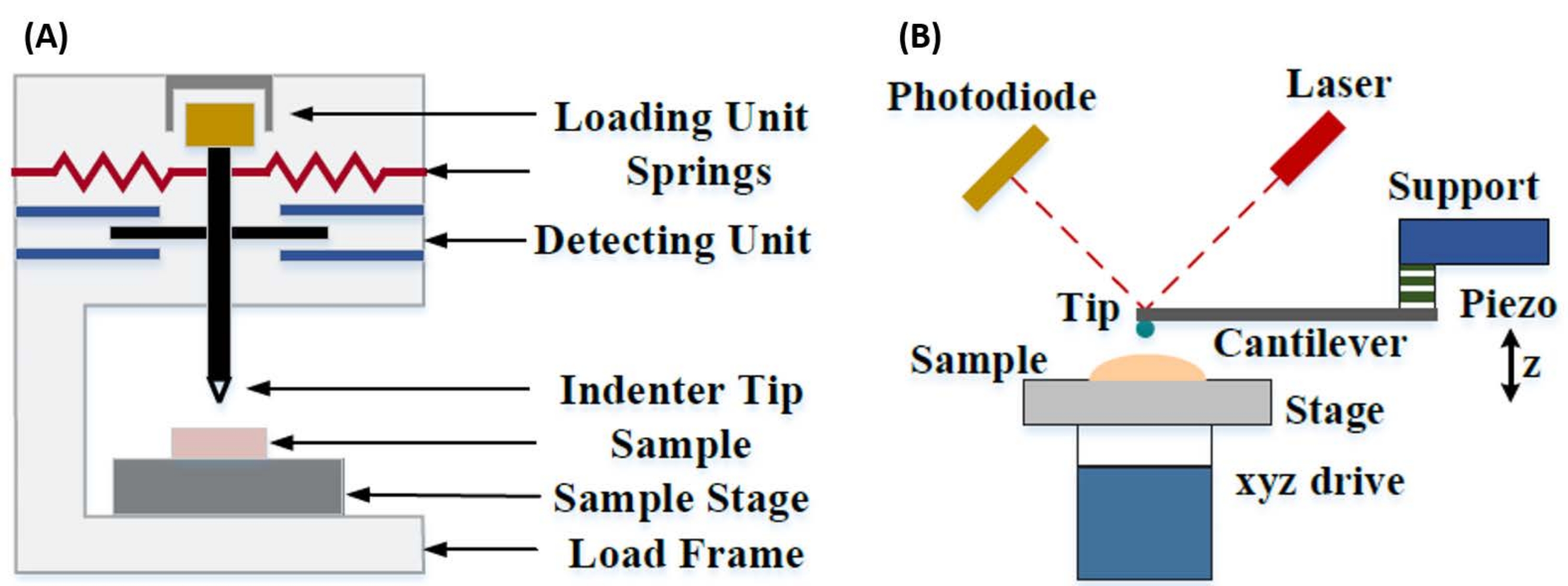
开发了仪器化纳米压痕,以改进通过各种显微硬度测试方法获得的相对值,提高用于分析机械性能的空间分辨率,并能够分析薄膜。重要的是,通过利用Oliver和Pharr7首先开发的方法,可以通过仪器化纳米压痕确定样品材料的弹性或杨氏模量E。此外,通过使用Berkovich三面锥体纳米压痕探头(其理想的尖端面积函数与维氏四面锥体探头相匹配)8,可以直接比较纳米级和更传统的微米级硬度测量。随着AFM的普及,基于AFM悬臂的纳米压痕也开始受到关注,特别是在测量较软材料的机械性能方面。因此,如图1所示,目前用于询问和量化纳米级机械性能的两种最常用的技术是仪器化纳米压痕(图1A)和基于AFM悬臂的纳米压痕(图1B)9,后者是本工作的重点。

图 1:仪器化和基于 AFM 悬臂的纳米压痕系统的比较。 示意图描述了用于进行(A)仪器化纳米压痕和(B)基于AFM悬臂的纳米压痕的典型系统。这个数字是从钱等人51修改而来的。缩写:AFM = 原子力显微镜。 请点击此处查看此图的大图。
仪器化和基于AFM悬臂的纳米压痕都使用刚性探针使感兴趣的样品表面变形,并监测合力和位移作为时间的函数。通常,所需的负载(即力)或(Z压电)位移曲线由用户 通过 软件界面指定并由仪器直接控制,而另一个参数则被测量。最常从纳米压痕实验中获得的机械性能是弹性模量(E),也称为杨氏模量,它具有压力单位。材料的弹性模量是与粘结刚度有关的基本属性,定义为在塑性变形开始之前,拉伸或压应力(σ,每单位面积施加的力)与轴向应变(ε,沿压痕轴的比例变形)之比(即可逆或暂时)变形(方程 [1]):
 (1)
(1)
应该注意的是,由于许多材料(特别是生物组织)实际上是粘弹性的,因此实际上,(动态或复杂)模量由弹性(存储,同相)和粘性(损失,异相)成分组成。在实际操作中,在纳米压痕实验中测量的是还原模量 E*,它与目标的真实样品模量 E有关,如公式(2)所示:
 (二)
(二)
其中 E 尖端和 ν 尖端分别是纳米压痕尖端的弹性模量和泊松比,ν 是样品的估计泊松比。泊松比是横向应变与轴向应变的负比,因此表示样品在承受轴向应变时(例如,在纳米压痕载荷期间)的横向伸长程度,如公式(3)所示:
 (三)
(三)
从降低模量转换为实际模量是必要的,因为a)压头尖端施加的一些轴向应变可以转换为横向应变(即,样品可能通过垂直于加载方向的膨胀或收缩而变形),以及b)压头不是无限硬的,因此压痕样品的行为导致尖端的一些(小)变形量。请注意,在E尖端>>E的情况下(即压头比样品硬得多,这在使用金刚石探头时通常是正确的),减少的样品模量和实际样品模量之间的关系大大简化为E ≈ E*(1 - v2)。 虽然仪器化纳米压痕在准确的力表征和动态范围方面具有优势,但基于AFM悬臂的纳米压痕速度更快,提供更高数量级的力和位移灵敏度,可实现更高分辨率的成像和改进的压痕定位,并且可以同时探测纳米级的磁性和电学特性9.特别是,基于AFM悬臂的纳米压痕在纳米级软材料(例如,聚合物,凝胶,脂质双层和细胞或其他生物材料),极薄(亚μm)薄膜(基底效应可能取决于压痕深度)10,11和悬浮二维(2D)材料12,13,14(例如石墨烯)的纳米级机械性能方面具有优越性15,16,云母17,六方氮化硼(h-BN)18或过渡金属硫族化物(TMDC;例如MoS2)19。这是由于其精细的力(sub-nN)和位移(sub-nm)灵敏度,这对于准确确定初始接触点并保持在弹性变形区域内非常重要。
在基于AFM悬臂的纳米压痕中,AFM探针向样品表面的位移由校准的压电元件驱动(图1B),柔性悬臂最终由于与样品表面接触时经历的电阻力而弯曲。悬臂的这种弯曲或偏转通常通过将激光从悬臂背面反射到光电探测器(位置敏感探测器 [PSD])中来监测。再加上悬臂刚度(以nN / nm为单位)和偏转灵敏度(以nm/V为单位)的知识,可以将测量的悬臂挠度(以V为单位)转换为施加在样品上的力(以nN为单位)。接触后,Z-压电运动和悬臂偏转之间的差异会产生样品压痕深度。结合尖端面积功能的知识,可以计算尖端-样品接触面积。然后可以使用适当的接触力学模型(请参阅讨论的 数据分析 部分)拟合所得力-距离或力-位移(F-D)曲线的接触部分的斜率,以确定样品的纳米力学性能。虽然基于AFM悬臂的纳米压痕与上述仪器化纳米压痕相比具有一些明显的优势,但它也带来了一些实际实施挑战,例如校准,尖端磨损和数据分析,本文将对此进行讨论。基于AFM悬臂的纳米压痕的另一个潜在缺点是假设线性弹性,因为接触半径和压痕深度需要远小于压头半径,这在使用纳米级AFM探头和/或表现出显着表面粗糙度的样品时可能难以实现。
传统上,纳米压痕仅限于单个位置或小网格压痕实验,其中选择所需的位置(即感兴趣区域[ROI])并且单个受控压痕,单个位置中的多个压痕由一些等待时间隔开,和/或以Hz量级的速率执行缩进的粗网格。然而,AFM的最新进展允许通过使用基于高速力曲线的成像模式(根据系统制造商的不同商品名称)同时获取机械性能和形貌,其中力曲线在负载控制下以kHz速率进行,最大尖端样品力用作成像设定点。还开发了傻瓜式方法,允许获取AFM形貌图像,然后在图像内的兴趣点进行选择性纳米压痕,从而对纳米压痕位置进行纳米级空间控制。虽然不是这项工作的主要重点,但代表性结果中提供了基于力曲线的成像和基于傻瓜悬臂的纳米压痕的特定 选定应用示例 ,并且可以与下面概述的协议结合使用(如果在采用的特定AFM平台上可用)。具体来说,这项工作概述了在任何有能力的AFM系统上实际实施基于AFM悬臂的纳米压痕的通用协议,并提供了该技术的四个用例示例(两个在空气中,两个在流体中),包括代表性结果和对细微差别的深入讨论,挑战和成功使用该技术的重要考虑因素。
研究方案
注意:由于商用AFM种类繁多,并且基于悬臂的纳米压痕存在多种样品类型和应用,因此以下方案有意设计为相对通用的性质,侧重于所有悬臂式纳米压痕实验所需的共享步骤,无论仪器或制造商如何。正因为如此,作者假设读者至少对操作用于执行悬臂式纳米压痕的特定仪器具有基本的熟悉程度。然而,除了下面概述的一般协议外,还包括特定于AFM和此处使用的软件的详细分步标准操作程序(SOP)(参见材料 表),重点是悬臂式样品在流体中的纳米压痕,作为 补充材料。
1. 样品制备和仪器设置
- 在不改变感兴趣区域的机械性能的情况下,以最小化表面粗糙度(理想情况下为纳米级,比预期的压痕深度小~10倍)和污染的方式制备样品。
- 根据介质(即空气或流体)、预期模量、样品形貌和相关特征尺寸选择合适的AFM探针,对目标样品进行纳米压痕(请参阅讨论中的 探针选择注意事项 )。将探头装载到探头支架上(参见 材料表),并将探头支架连接到AFM扫描头。
- 在AFM软件中选择合适的纳米压痕模式,使用户能够控制单个斜坡(即力-位移曲线)。
注意:不同AFM制造商和单个仪器的具体模式会有所不同(有关更多详细信息和具体示例,请参阅 补充材料 中提供的SOP)。 - 将激光对准探头悬臂的背面,与探头尖端的位置相对并进入PSD。
注意:有关对准激光和在流体中进行纳米压痕时的重要考虑因素的更多详细信息,请参阅间充质干细胞 应用示例 ,特别是避免漂浮的碎片和/或气泡,这些碎片和/或气泡会散射或折射光束。AFM光学元件可能还需要调整,以补偿流体的折射率,并避免在啮合表面时使探头崩溃。- 通过最大化总电压,将激光束光斑居中悬臂背面(图2A)。
- 通过将 X 和 Y(即水平和垂直)偏转信号调整为尽可能接近零,将反射的激光束光斑居中在 PSD 上(图 2A),从而提供最大的可检测偏转范围,以产生与悬臂偏转成比例的输出电压。
- 如果不确定样品形貌、表面粗糙度和/或表面密度(在薄片或颗粒的情况下),请在进行任何纳米压痕实验之前进行AFM形貌测量扫描,以确认样品的适用性,如步骤1.1和样品制备部分所述讨论。

图 2:位置敏感探测器监视器。 (A) PSD显示,指示在与样品表面接合之前,正确对准的激光从探头悬臂的背面反射到PSD的中心(如大总电压和没有垂直或水平偏转所证明的那样)(即探头与样品脱离接触)。(B)当悬臂偏转时(例如,当探头与样品接触时),垂直偏转电压增加。缩写:PSD = 位置敏感探测器;垂直 = 垂直;霍里兹 = 水平;AMPL = 振幅;不适用 = 不适用。 请点击此处查看此图的大图。
2. 探头校准
注意:使用悬臂纳米压痕期间收集的F-D曲线数据量化样品的机械性能需要三个值: 悬臂/ PSD系统的偏转灵敏度(DS )(nm / V或V / nm), 悬臂弹簧常数 (nN / nm)和探针 接触面积,通常以给定压痕深度下的有效探针尖端半径(nm)表示,小于球形探针的探头半径提示。
- 通过在极硬的材料(例如蓝宝石, E = 345 GPa)上斜坡来校准探头/AFM系统的DS,以便最小化样品的变形,从而在尖端 - 样品接触开始后测量的压电陶瓷Z运动仅转换为悬臂偏转。
注意:DS校准必须在与计划的纳米压痕实验相同的条件下进行(即温度,介质等),以准确反映实验期间系统的DS。可能需要很长(30分钟)的激光预热期才能获得最大精度,以便有时间达到热平衡并建立稳定的激光输出功率和指向稳定性。 每次 重新对准激光时都必须重新测量 DS,即使使用相同的探头,因为 DS 取决于激光强度和悬臂上的位置,以及探头反射的质量(即探头背面涂层的退化会影响 DS)和 PSD20 的灵敏度。- 在蓝宝石上设置并执行 DS 校准压痕,以实现与计划样品 压痕 大致相同的探头偏转(以 V 或 nm 为单位),因为测量的位移是尖端偏转角的函数,并且在大挠度时变为非线性。
- 确定DS(以nm/V为单位),或者从所得F-D曲线中初始接触点之后接触状态的线性部分的斜率确定 反向 光学杠杆灵敏度(以V/nm为单位),如图 3A所示。
- 重复斜坡至少 5 次,记录每个 DS 值。使用值的平均值以获得最大精度。如果测量的相对标准偏差(RSD)超过~1%,则重新测量DS,因为有时由于最初引入粘附力,前几条F-D曲线不理想。
- 如果探头悬臂的 弹簧常数 k 未经过工厂校准(例如, 通过 激光多普勒测振法 [LDV]),请校准弹簧常数。
注意:热调谐方法最适合k<10 N/m的相对柔软的悬臂(有关替代方法的列表和说明,请参阅讨论的弹簧常数部分,特别是对于k>10 N/m的刚性悬臂)。如图3B,C所示,热调谐通常集成到AFM控制软件中。
- 如果探头没有出厂校准的尖端半径测量(例如, 通过 扫描电子显微镜[SEM]成像),则测量有效尖端半径 R。
注意:测量尖端半径有两种常用方法(请参阅相应的讨论部分),但纳米级探针尖端最常见的方法是盲尖重建(BTR)方法,该方法利用粗糙度标准(参见材料表),其中包含许多极其尖锐(亚nm)特征,用于有效地对尖端进行成像,而不是尖端对样品进行成像。- 如果使用BTR方法,请使用慢速扫描速率(<0.5 Hz)和高反馈增益对粗糙度(尖端表征)样品进行成像,以帮助优化对非常清晰的特征的跟踪。根据预期的尖端半径选择图像尺寸和像素密度(分辨率)(例如,3 μm x 3 μm区域的1024 x 1024像素图像将具有~3 nm横向分辨率)。
- 使用AFM图像分析软件(参见材料表)对探针尖端进行建模,并在预期的样品压痕深度处估计其末端半径和有效尖端直径,如图3D-F所示。
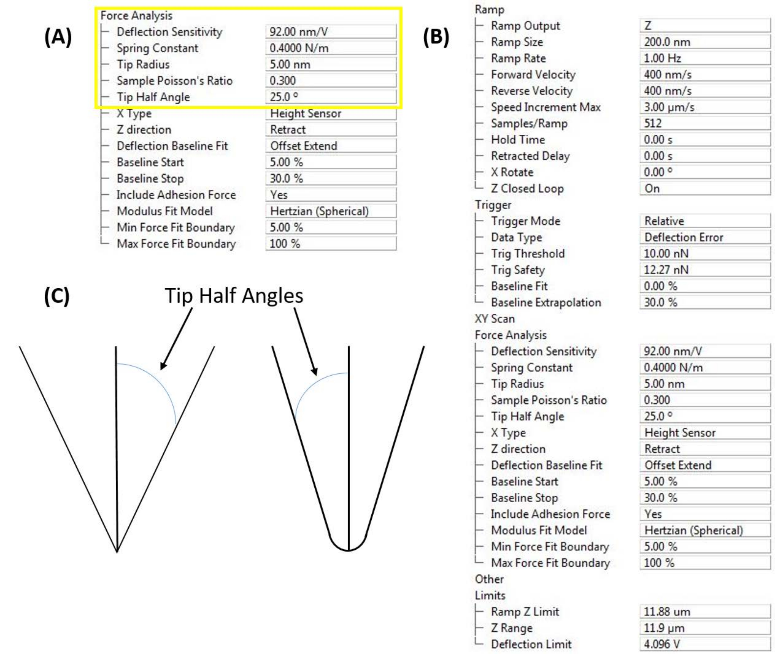
- 完成探头校准后,在仪器软件中输入 DS、 k 和 R 值,如图 4A 所示。
- 输入样品泊松比 ν 的估计值,以便将测量的还原模量转换为实际样本模量9。如果采用基于尖端形状和压痕深度的圆锥形或圆锥形接触力学模型,则还需要输入尖端半角(图4C)。
注意:模量对估计泊松比中的小误差或不确定性相对不敏感。ν = 0.2-0.3的估计值是许多材料的良好起点21。
- 输入样品泊松比 ν 的估计值,以便将测量的还原模量转换为实际样本模量9。如果采用基于尖端形状和压痕深度的圆锥形或圆锥形接触力学模型,则还需要输入尖端半角(图4C)。

图 3:探头校准。 (A) 偏转灵敏度测定。在蓝宝石衬底(E = 345 GPa)上进行的具有代表性的偏转灵敏度测量的结果,用于具有反射背面铝涂层的标准攻丝模式探头(标称k = 42 N/m;参见材料表)。图中显示了测量的进近(蓝色迹线)和退刀或退线(红色迹线)曲线。测得的偏转灵敏度为59.16 nm/V,通过拟合捕捉接触点和转弯点之间的接近曲线来确定,如垂直虚线之间的区域所示。在拉开表面之前,缩回/退缩曲线中明显的负向偏转区域表明尖端-样品粘附。(乙,丙)热调谐。代表性悬臂热噪声光谱(蓝色迹线)与两个不同探头的相应拟合(红色迹线)。(B) 基于标准力曲线的AFM成像探头(见材料表)的热调谐设置和拟合参数,其标称弹簧常数k = 0.4 N / m用作初始猜测。悬臂热噪声频谱的拟合产生f 0 = 79.8 kHz的基波谐振频率,这与f0 = 70 kHz的标称值相当吻合。测得的Q因子为58.1。拟合优度 (R2 = 0.99) 基于拟合与两条垂直红色虚线之间的数据的一致性。请注意,了解并输入环境温度和挠度灵敏度以获得准确的结果非常重要。(C) 悬臂热噪声频谱和相应的拟合(即热调谐),计算出用于对活细胞和分离的细胞核进行纳米力学测量的极软悬臂的弹簧常数 k = 0.105 N/m。请注意,~2-3 kHz的固有谐振频率明显较低。(D-F)盲尖重建。金刚石尖端探头的代表性盲尖重建工作流程(标称R = 40 nm;参见材料表)。(D) 尖端表征样品的 5 μm x 5 μm 图像,由一系列极其锋利的 (亚纳米) 钛尖峰组成,用于对 AFM 探针尖端进行成像。(E)探针尖端的结果重建模型(倒置高度图像)。(F) 盲尖重建拟合结果,包括用户选择的距尖端顶点 8 nm 高度(即压痕深度 << R)处估计的端半径 R = 29 nm 和有效尖端直径 40 nm,通过将该高度的针尖-样品接触面积转换为假设圆形轮廓的有效直径(即, A = πr 2 = π(d/2)2),用于球面接触力学模型。缩写:AFM = 原子力显微镜;ETD = 有效尖端直径。请点击此处查看此图的大图。

图 4:软件接口输入。 (A) 探头校准常数。软件用户界面(参见 材料表)用于输入测量的偏转灵敏度、弹簧常数和尖端半径,以实现定量纳米力学测量。探针和样品的泊松比对于从悬臂式纳米压痕力曲线计算样品的弹性或杨氏模量是必需的。(B) 坡道控制窗口。软件用户界面(参见 材料表),用于设置基于悬臂的纳米压痕实验,分为描述斜坡本身(即压痕曲线)、仪器触发(例如力与位移控制)、后续力分析和移动限制的参数(通过缩小 A/D 转换器在控制 Z 压电和读取 PSD 偏转时必须操作的范围来提高测量灵敏度)。(C) 如果使用圆锥形、金字塔形或圆锥形接触力学模型(例如 Sneddon),则尖端半角(基于探头几何形状或直接测量)很重要。 请点击此处查看此图的大图。
3. 收集力-位移 (F-D) 数据
注意:此处提供的参数值(见 图4B)可能因给定样品的力和压痕范围而异。
- 在AFM头下导航样品,并在所需的感兴趣区域接合。
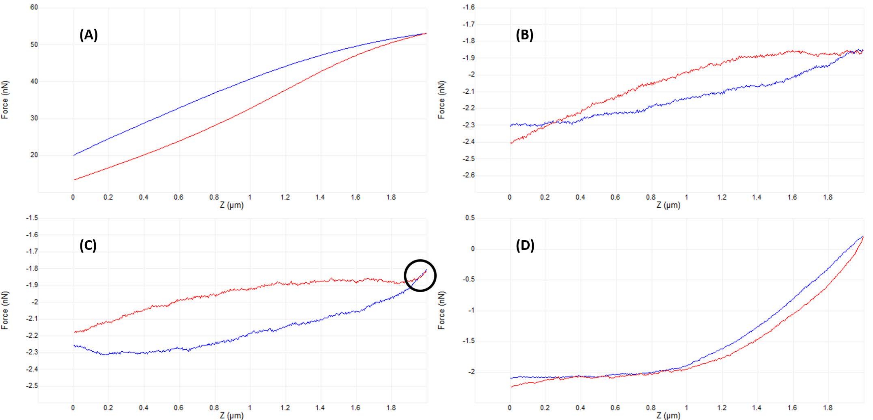
- 监测垂直偏转信号(图2B)或执行小(~50-200nm)初始斜坡(图4B)以验证尖端和样品是否接触(见图5A)。
- 稍微向上调整AFM头部位置(步长相当于全斜坡尺寸的~50%)并再次斜坡。重复直到尖端和样品刚好不接触,如几乎平坦的斜坡(图5B)和悬臂的最小垂直偏转(图2A)所证明的那样。
- 一旦不存在明显的针尖-样品相互作用(比较图2A和图2B),将AFM头降低相当于斜坡尺寸的~50%-100%,以确保探头在手动移动AFM头时不会撞到样品中。再次斜坡,重复直到观察到良好的曲线(图5D)或类似于图5C的曲线。在后一种情况下,执行一次额外的小的AFM降头调整,等于斜坡尺寸的~20%-50%,以获得良好的接触和类似于图5D所示的力曲线。
- 调整斜坡参数(如下所述,如 图 4B) 以针对仪器、探头和样品进行优化,并获得类似于 图 5D.
- 根据样品(例如厚度、预期模量、表面粗糙度)和所需的压痕深度选择合适的斜坡尺寸(即,通过一个斜坡周期的总Z压电运动)。
注意:对于较硬的样品,可能会发生较少的样品变形(因此对于给定的Z压电运动,探针偏转更大),因此斜坡尺寸通常可以小于较软的样品。刚性样品和悬臂的典型斜坡尺寸可能为数十纳米,而软样品和悬臂的斜坡尺寸可能为数百纳米至几微米;具体选定的 应用示例 在代表性结果部分提供。请注意,最小和最大可能的斜坡尺寸取决于仪器。 - 选择合适的斜坡速率(1 Hz是大多数样品的良好起点)。
注意:斜坡速率可能受到控制和/或检测电子速度/带宽的限制。结合斜坡尺寸,斜坡速率决定了倾斜速度。在压痕软材料时,尖端速度尤为重要,因为粘弹性效应可能导致滞后伪影9,22。 - 选择是采用触发(负载控制)还是非触发(位移控制)斜坡。
注意:在触发斜坡中,系统将以用户定义的步骤(基于斜坡大小和分辨率或数据点数量)接近样品,直到检测到所需的触发阈值(即设定点力或悬臂偏转),此时系统将缩回其原始位置并显示F-D曲线。在未触发斜坡中,系统只需将Z压电二极管延长用户定义的斜坡尺寸指定的距离,并显示测量的F-D曲线。对于大多数用例,触发斜坡是首选,但在研究没有尖锐、易于识别的接触点的软材料时,未触发斜坡可能很有用。- 如果选择了触发斜坡,请设置触发阈值(用户定义的最大允许力或斜坡偏转),以在样品中产生所需的压痕。
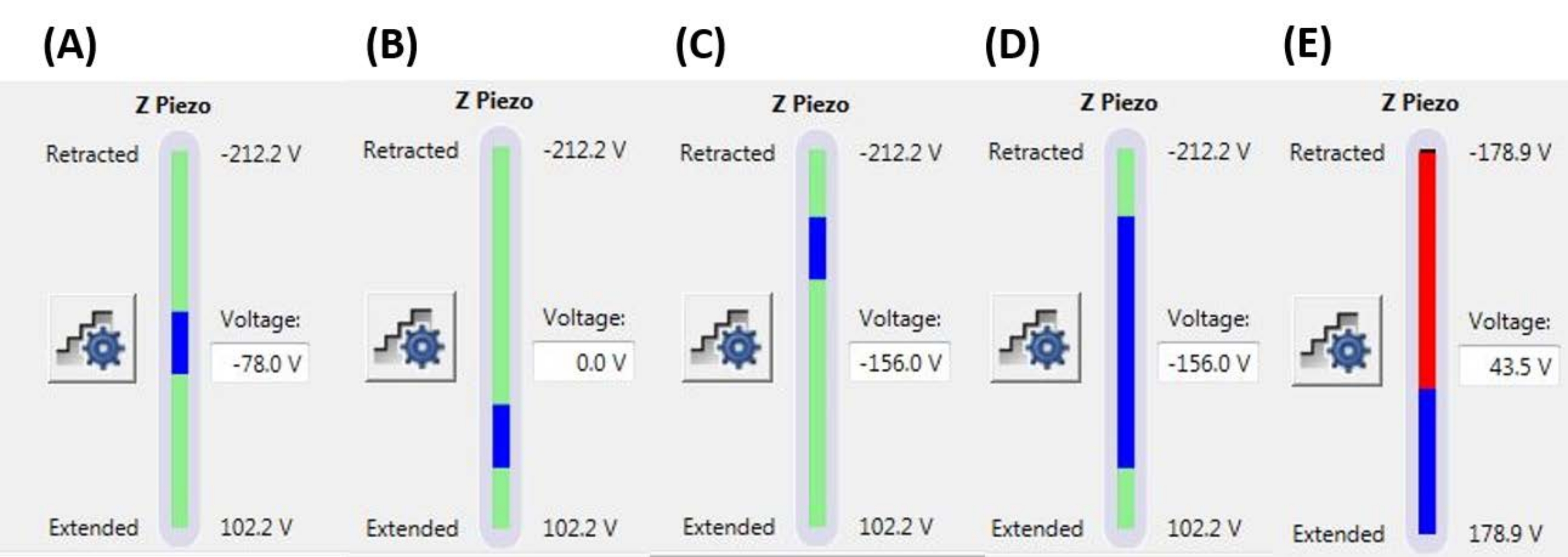
注意:使用触发阈值意味着斜坡可能会在达到指定的完整斜坡尺寸(Z-压电延伸)之前终止(即,探头可能开始缩回)。值范围从几nN到几μN,具体取决于针尖样品系统。 - 设置斜坡位置以确定Z压电陶瓷最大范围内将用于执行 斜坡 的部分。确保 斜坡尺寸的总 范围不会在最大Z压电效应范围之外开始或结束(参见 图6中的代表性示例),否则F-D曲线的一部分将不代表任何物理测量值(即,Z压电陶瓷将完全伸展或缩回,而不是移动)。
- 如果选择了触发斜坡,请设置触发阈值(用户定义的最大允许力或斜坡偏转),以在样品中产生所需的压痕。
- 设置 每个斜坡的样本数 (例如,512个样本/斜坡)以实现所需的测量分辨率(即F-D曲线的点密度)。
注意:最大采样/斜坡可能受到软件(文件大小)或硬件限制(例如,模拟到数字[A/D]转换速度,取决于斜坡速率)的限制。还可以限制允许的Z压电或偏转范围(参见 图4B中的限制参数),以提高系统A/D转换器的有效分辨率。 - 设置 X 旋转 以减少样品和尖端上的剪切力,方法是同时在 X 方向(平行于悬臂)上稍微移动探头,同时在 Z 方向(垂直于悬臂)上缩进。X旋转值等于探头支架相对于表面法线的偏移角度(典型值为12°)。
注意:X 旋转是必要的,因为悬臂以相对于表面的小角度安装在探头支架中,以允许入射激光束反射到 PSD 中。此外,探头尖端的前后角度可能彼此不同(即,探针尖端可能是不对称的)。更具体的信息可以从各个探头和AFM制造商处获得。
- 根据样品(例如厚度、预期模量、表面粗糙度)和所需的压痕深度选择合适的斜坡尺寸(即,通过一个斜坡周期的总Z压电运动)。

图 5:在啮合后优化针尖-样品分离以获得良好的力曲线。 在活间充质干细胞核上压入液体(磷酸盐缓冲盐水)时获得的代表性力-位移曲线的连续示例,带有校准的软氮化硅悬臂(标称 k = 0.04 N / m),终止于半径为5μm的半球形尖端(参见 材料表)。在啮合细胞表面和优化压痕参数的过程中获得曲线,探头方法以蓝色显示,缩回/撤回以红色显示。(A)在开始斜坡之前,尖端已经与样品啮合并接触,导致悬臂挠度和力较大,没有平坦的预接触基线。(B)手动将尖端移动到离样品足够远的地方后,未触发的2μm斜坡导致F-D曲线几乎平坦(即力几乎没有变化)。在环境条件下,曲线会更平坦,但在流体中,介质的粘度会导致探头悬臂在斜坡期间轻微偏转,即使没有表面接触也是如此。(C)在开始斜坡之前稍微接近表面后,接近和退刀曲线在斜坡的转弯点附近显示出力(增加的坡度)略有增加(即从接近到撤退的过渡)。要寻找的迹象是接近(蓝色)和退弧(红色)曲线开始重叠(黑色圆圈表示的区域),这表明与表面的物理相互作用。(D) 在优化斜坡参数并比 C 中更接近电池表面略微 (~1 μm) 后获得的理想 F-D 曲线,以便探头花费大约一半的斜坡与电池接触,从而产生足够的变形以拟合接近曲线的接触部分并确定弹性模量。相对较长、平坦、低噪声的基线使拟合算法更容易确定接触点。缩写:F-D = 力-位移。 请点击此处查看此图的大图。

图 6:斜坡尺寸和位置。 Z-压电监视器显示斜坡的范围(蓝色条)相对于总可用Z压电运动范围(绿色条)。(A) Z-压电位置接近其运动范围的中间,如蓝色条大致位于绿色条的中间和当前的Z压电电压(-78.0 V)大致在其完全缩回(-212.2 V)和扩展(+102.2 V)值之间。(B) Z-压电相对于A扩展,不施加偏置电压。(C) Z-压电相对于A和B缩回。(D) Z-压电陶瓷位置与C中的Z压电陶瓷位置相同,电压-156.0 V,但斜坡尺寸相对于A-C增加,以利用Z压电陶瓷的全范围运动。€ 斜坡尺寸对于当前斜坡位置来说太大,导致 Z 压电扩展到其范围的末端。这将导致F-D曲线变平,因为系统无法进一步扩展Z压电陶瓷。缩写:F-D = 力-位移。请点击此处查看此图的大图。
4. F-D曲线分析
- 选择合适的数据分析软件包。选择并加载要分析的数据。
注意:许多AFM制造商和AFM图像处理软件程序都内置了对F-D曲线分析的支持。或者,专用F-D曲线分析包(例如开源AtomicJ软件包)的灵活性和功能增加可能是有益的23,特别是对于大型数据集的批处理和统计分析或实现复杂的接触力学模型。 - 输入弹簧常数、DS和探头尖端半径的校准值,以及探针尖端的杨氏模量和泊松比的估计值(基于其材料成分)和样品的泊松比。
注意: 如果使用金刚石尖端压头,则值 E 尖端 = 1140 GPa 和 ν尖端 = 0.07 可用于21,24,25,26。对于标准硅探针,通常可以使用E尖端= 170 GPa和ν尖端= 0.27,尽管硅的杨氏模量因晶体取向而变化27。 - 选择适合针尖和样品的纳米压痕接触力学模型。
注意:对于许多常见的球形吸头型号(例如,赫兹、莫吉斯、DMT、JKR),样品的压痕深度必须小于针尖半径;否则,探头尖端的球形几何形状会让位于圆锥形或金字塔形(图4C)。对于圆锥形(例如,Sneddon28)和金字塔形模型,尖端半角(即尖端侧壁与垂直于尖端的平分线之间的角度; 图4C)必须知道,并且通常可从探头制造商处获得。有关接触力学模型的更多信息,请参阅thedDiscussion的 数据分析 部分。 - 运行拟合算法。检查 F-D 曲线是否正确拟合;对应于接近单位的平均 R 2 的低残余误差(例如,R2 > 0.9)通常表明与所选模型29,30 的良好拟合。如果需要,抽查单个曲线以目视检查曲线、模型拟合和计算的接触点(例如,请参阅图 7 和讨论的数据分析部分)。
结果
力-位移曲线
图 7 显示了在树脂嵌入的枇杷松样品(图 7A)和间充质干细胞 (MSC) 细胞核上的液体(磷酸盐缓冲盐水 [PBS])上进行的纳米压痕实验中获得的具有代表性的、近乎理想的 F-D 曲线(图 7B)。任何接触力学模型的使用都依赖于对初始针尖-样品接触点的准确可靠测定。因此,初始接触点之前相对平坦、低?...
讨论
样品制备
对于空气中的纳米压痕,常见的制备方法包括冷冻切片(例如,组织样品)、研磨和/或抛光,然后进行超薄切片(例如,树脂嵌入的生物样品)、离子研磨或聚焦离子束制备(例如,不适合抛光的半导体、多孔或混合硬度样品)、机械或电化学抛光(例如,金属合金)或薄膜沉积(例如,原子层或化学气相沉积, 分子束外延)。目标是创建具有最小表面粗糙度的样品(?...
披露声明
作者没有利益冲突需要披露。
致谢
所有AFM实验均在博伊西州立大学表面科学实验室(SSL)进行。SEM表征在博伊西州立材料表征中心(BSCMC)进行。本出版物中报道的有关生物燃料原料的研究得到了美国能源部、能源效率和可再生能源办公室、生物能源技术办公室作为原料转换接口联盟 (FCIC) 的一部分以及美国能源部爱达荷州运营办公室合同 DE-AC07-051ID14517 的部分支持。细胞力学研究得到了美国国立卫生研究院(美国)AG059923、AR075803和P20GM109095的资助,以及美国国家科学基金会(美国)的1929188和2025505资助。模型脂质双层系统工作得到了美国国立卫生研究院(美国)R01 EY030067资助的支持。作者感谢Elton Graugnard博士制作了 图11所示的合成图像。
材料
| Name | Company | Catalog Number | Comments |
| Atomic force microscope | Bruker | Dimension Icon | Uses Nanoscope control software, including PeakForce Quantitative Nanomechanical Mapping (PF-QNM), FastForce Volume (FFV), and Point-and-Shoot Ramping experimental workspaces |
| AtomicJ | American Institute of Physics | https://doi.org/10.1063/1.4881683 | Flexible, powerful, free open source Java-based force curve analysis software package. Supports numerous contact mechanic models, such as Hertz, Sneddon DMT, JKR, Maugis, and cone or pyramid (including blunt and truncated). Also includes a variety of initial contact point estimation methods to choose from. Supports batch processing of data and subsequent statistical analysis (e.g., averages, standard deviations, histograms, goodness of fit, etc.). Literature citation is: P. Hermanowicz, M. Sarna, K. Burda, and H. Gabry , “AtomicJ: An open source software for analysis of force curves” Rev. Sci. Instrum. 85: 063703 (2014), https://doi.org/10.1063/1.4881683 , “AtomicJ: An open source software for analysis of force curves” Rev. Sci. Instrum. 85: 063703 (2014), https://doi.org/10.1063/1.4881683 |
| Buffer solution (PBS) | Fisher Chemical (NaCl), Sigma Aldrich (KCl), Fisher BioReagents (Na2HPO4 and KH2PO4) | S271 (>99% purity NaCl), P9541 (>99% purity KCl), BP332(>99% purity Na2HPO4), BP362 (>99% purity KH2PO4) | Phosphate buffered saline (PBS) was prepared in the laboratory as an aqueous solution consisting of 137 mM NaCl, 2.7 mM KCl, 10 mM Na2HPO4, and 1.8 mM KH2PO4 dissolved in ultrapure water. Reagents were measured out using an analytical balance, and glassware was cleaned with soap and water followed by autoclaving immediately prior to use. |
| Chloroform | |||
| Diamond tip AFM probe | Bruker | PDNISP | Pre-mounted factory-calibrated cube corner diamond (E = 1140 GPa) tip AFM probe (nominal R = 40 nm) with a stainless steel cantilever (nominal k = 225 N/m, f0 = 50 kHz). Spring constant is measured at the factory (k = 256 N/m for the probe, Serial #13435414, used here) and calibration data (including AFM images of indents showing probe geometry) is provided with the probe. |
| Diamond ultramicrotome blade | Diatome | Ultra 35° | 2.1 mm width. Also used a standard glass blade for intial rough cut of sample surface before transitioning to diamond blade for final surface preparation |
| Epoxy | Gorilla Glue | 26853-31-6 | Epoxy resin and hardner were mixed in a 1:1 ratio, a small drop was placed on a stainless steel sample puck (Ted Pella), and V1 grade muscovite mica (Ted Pella) was attached to create an atomically flat surface for preparation of phospholipid membranes. |
| Ethanol | |||
| LR white resin, medium grade (catalyzed) | Electron Microscopy Sciences | 14381 | 500 mL bottle, Lot #150629 |
| Mesenchymal stem cells (MSCs) | N/A | N/A | MSCs for nanomechanical studies were primary cells harvested from 8-10 week old male C57BL/6 mice as described in Goelzer, M. et al. "Lamin A/C Is Dispensable to Mechanical Repression of Adipogenesis" Int J Mol Sci 22: 6580 (2021) doi:10.3390/ijms22126580 and Peister, A. et al. "Adult stem cells from bone marrow (MSCs) isolated from different strains of inbred mice vary in surface epitopes, rates of proliferation, and differentiation potential" Blood 103: 1662-1668 (2004), doi:10.1182/blood-2003-09-3070. |
| Modulus standards | Bruker | PFQNM-SMPKIT-12M | Used HOPG (E = 18 GPa) and PS (E = 2.7 GPa). Also contains 2x PDMS (Tack 0, E = 2.5 MPa; Tack 4, E = 3.5 MPa), PS-LDPE (E = 2.0/0.2 GPa), fused silica (E = 72.9 GPa), sapphire (E - 345 GPa), and tip characterization (titanium roughness) sample. All samples come pre-mounted on a 12 mm diameter steel disc (sample puck). |
| Muscovite mica | Ted Pella | 50-12 | 12 mm diameter, V1 grade muscovite mica |
| Nanscope Analysis | Bruker | Version 2.0 | Free AFM image processing and analysis software package, but designed for, and proprietary/limited to Bruker AFMs; similar functionality is available from free, platform-independent AFM image processing and analysis software packages such as Gwyddion, WSxM, and others. Has built-in capabilities for force curve analysis, but AtomicJ is more flexible/full featured (e.g., more built-in contact mechanics models to choose from, statistical analysis of force curve fitting results, etc.) for force curve analysis and handles batch processing of force curves. |
| Phospholipids: POPC, Cholesterol (ovine) | Avanti Polar Lipids | POPC: CAS # 26853-31-6, Cholesterol: CAS # 57-88-5 | POPC lipid dissolved in chloroform (25 mg/mL) was obtained from vendor and used without further purification. Cholesterol powder from the same vendor was dissolved in chloroform (20 mg/mL). |
| Probe holder (fluid, lipid bilayers) | Bruker | MTFML-V2 | Specific to the particular AFM used; MTFML-V2 is a glass probe holder for scanning in fluid on a MultiMode AFM. |
| Probe holder (fluid, MSCs) | Bruker | FastScan Bio Z-scanner | Used with Dimension FastScan head (XY flexure scanners). Serial number MXYPOM5-1B154. |
| Probe holder (standard, ambient) | Bruker | DAFMCH | Specific to the particular AFM used; DAFMCH is the standard contact and tapping mode probe holder for the Dimension Icon AFM, suitable for nanoindentation (PF-QNM, FFV, and point-and-shoot ramping) |
| Sample Puck | Ted Pella | 16218 | Product number is for 15 mm diameter stainless steel sample puck. Also available in 6 mm, 10 mm, 12 mm, and 20 mm diameters at https://www.tedpella.com/AFM_html/AFM.aspx#anchor842459 |
| Sapphire substrate | Bruker | PFQNM-SMPKIT-12M | Extremely hard surface (E = 345 GPa) for measuring deflection sensitivity of probes (want all of the deflection to come from the probe, not the substrate). Part of the PF-QNM/modulus standards kit. |
| Scanning electron microscope | Hitachi | S-3400N-II | Located at Boise State. Used to perform co-localized SEM/EDS on all samples except additively manufactured (AM) Ti-6Al-4V. |
| Silicon AFM probes (standard) | NuNano | Scout 350 | Standard tapping mode silicon probe with reflective aluminum backside coating; k = 42 N/m (nominal), f0 = 350 kHz. Nominal R = 5 nm. Also available uncoated or with reflective gold backside coating. Probes with similar specifications are available from other manufacturers (e.g., Bruker TESPA-V2). |
| Silicon AFM probes (stiff) | Bruker | RTESPA-525, RTESPA-525-30 | Rotated tip etched silicon probes with reflective aluminum backside coating; k = 200 N/m (nominal), f0 = 525 kHz. Nominal R = 8 nm for RTESPA-525, R = 30 nm for RTESPA-525-30. Spring constant of each RTESPA-525-30 is measured individually at the factory via laser Doppler vibrometry and supplied with the probe. |
| Silicon carbide grit paper (abrasive discs) | Allied | 50-10005 | 120 grit |
| Silicon nitride AFM probes (soft, large radius hemispherical tip) | Bruker | MLCT-SPH-5UM, MLCT-SPH-5UM-DC | Also MLCT-SPH-1UM-DC. New product line of factory-calibrated (probe radius and spring constants of all cantilevers) large radius (R = 1 or 5 mm) hemispherical tip (at the end of a 23 mm long cylindrical shaft) probes. DC = drift compensation coating. 6 cantilevers/probe (A-F). Nominal spring constants: A, k = 0.07 N/m; B, k = 0.02 N/m; C, k = 0.01 N/m; D, k = 0.03 N/m; E, k = 0.1 N/m; F, k = 0.6 N/m. |
| Silicon nitride AFM probes (soft, medium sharp tip) | Bruker | DNP | 4 cantilevers/probe (A-d). Nominal spring constants: A, k = 0.35 N/m; B, k = 0.12 N/m; C, k = 0.24 N/m; D, k = 0.06 N/m. Nominal radii of curvature, R = 10 nm. |
| Silicon nitride AFM probes (soft, sharp tip) | Bruker | ScanAsyst-Air | Nominal values: resonance frequency, f0 = 70 kHz; spring constant, k = 0.4 N/m; radius of curvature, R = 2 nm. Designed for force curve based AFM imaging. |
| Superglue | Henkel | Loctite 495 | Cyanoacrylate based instant adhesive. Lots of roughly equivalent products are readily available. |
| Syringe pump | New Era Pump Systems | NE1000US | One channel syringe pump system with infusion and withdrawal capacity |
| Tip characterization standard | Bruker | PFQNM-SMPKIT-12M | Titanium (Ti) roughness standard. Part of the PF-QNM/modulus standards kit. |
| Ultrahigh purity nitrogen (UHP N2), 99.999% | Norco | SPG TUHPNI - T | T size compressed gas cylinder of ultrahigh purity (99.999%) nitrogen for drying samples |
| Ultramicrotome | Leica | EM UC6 | Equipped with a glass blade (standard, for intial sample preparation) and a diamond blade (for final preparation) |
| Ultrapure water | Thermo Fisher | Barnstead Nanopure Model 7146 | Model has been discontinued, but equivalent products are available. Produces ≥18.2 MΩ*cm ultrapure water with 1-5 ppb TOC (total organic content), per inline UV monitoring. Includes 0.2 µm particulate filter, ion exchange columns, and UV oxidation chamber. |
| Variable Speed Grinder | Buehler | EcoMet 3000 | Used with silicon carbide grit papers during hand polishing. |
| Vibration isolation table (active) | Herzan | TS-140 | Used with Bruker MultiMode AFM. Sits on a TMC 65-531 vibration isolation table. Bruker Dimension Icon AFM utilizes strictly passive vibration isolation (comes from manufacturer with custom acoustic hood, air table, and granite slab). |
| Vibration isolation table (passive) | TMC | 65-531 | 35" x 30" vibration isolation table with optional air damping (disabled). Used with Bruker MultiMode AFM. Herzan TS-140 "Table Stable" active vibration control table is located on top. |
参考文献
- Hart, E. W. Theory of the tensile test. Acta Metallurgica. 15 (2), 351-355 (1967).
- Fell, J. T., Newton, J. M. Determination of tablet strength by the diametral-compression test. Journal of Pharmaceutical Sciences. 59 (5), 688-691 (1970).
- Babiak, M., Gaff, M., Sikora, A., Hysek, &. #. 3. 5. 2. ;. Modulus of elasticity in three- and four-point bending of wood. Composite Structures. 204, 454-465 (2018).
- Song, S., Yovanovich, M. M. Relative contact pressure-Dependence on surface roughness and Vickers microhardness. Journal of Thermophysics and Heat Transfer. 2 (1), 43-47 (1988).
- Hays, C., Kendall, E. G. An analysis of Knoop microhardness. Metallography. 6 (4), 275-282 (1973).
- Hill, R., Storåkers, B., Zdunek, A. B. A theoretical study of the Brinell hardness test. Proceedings of the Royal Society of London. A. Mathematical and Physical Sciences. 423 (1865), 301-330 (1989).
- Oliver, W. C., Pharr, G. M. An improved technique for determining hardness and elastic modulus using load and displacement sensing indentation experiments. Journal of Materials Research. 7 (6), 1564-1583 (1992).
- Sakharova, N. A., Fernandes, J. V., Antunes, J. M., Oliveira, M. C. Comparison between Berkovich, Vickers and conical indentation tests: A three-dimensional numerical simulation study. International Journal of Solids and Structures. 46 (5), 1095-1104 (2009).
- Cohen, S. R., Kalfon-Cohen, E. Dynamic nanoindentation by instrumented nanoindentation and force microscopy: a comparative review. Beilstein Journal of Nanotechnology. 4 (1), 815-833 (2013).
- Saha, R., Nix, W. D. Effects of the substrate on the determination of thin film mechanical properties by nanoindentation. Acta Materialia. 50 (1), 23-38 (2002).
- Tsui, T. Y., Pharr, G. M. Substrate effects on nanoindentation mechanical property measurement of soft films on hard substrates. Journal of Materials Research. 14 (1), 292-301 (1999).
- Cao, G., Gao, H. Mechanical properties characterization of two-dimensional materials via nanoindentation experiments. Progress in Materials Science. 103, 558-595 (2019).
- Castellanos-Gomez, A., Singh, V., vander Zant, H. S. J., Steele, G. A. Mechanics of freely-suspended ultrathin layered materials. Annalen der Physik. 527 (1-2), 27-44 (2015).
- Cao, C., Sun, Y., Filleter, T. Characterizing mechanical behavior of atomically thin films: A review. Journal of Materials Research. 29 (3), 338-347 (2014).
- Lee, C., Wei, X., Kysar, J. W., Hone, J. Measurement of the elastic properties and intrinsic strength of monolayer graphene. Science. 321 (5887), 385-388 (2008).
- Elibol, K., et al. Visualising the strain distribution in suspended two-dimensional materials under local deformation. Scientific Reports. 6 (1), 28485 (2016).
- Castellanos-Gomez, A., et al. Mechanical properties of freely suspended atomically thin dielectric layers of mica. Nano Research. 5 (8), 550-557 (2012).
- Song, L., et al. Large scale growth and characterization of atomic hexagonal boron nitride layers. Nano Letters. 10 (8), 3209-3215 (2010).
- Castellanos-Gomez, A., et al. Elastic properties of freely suspended MoS2 nanosheets. Advanced Materials. 24 (6), 772-775 (2012).
- D'Costa, N. P., Hoh, J. H. Calibration of optical lever sensitivity for atomic force microscopy. Review of Scientific Instruments. 66 (10), 5096-5097 (1995).
- Wu, Y., et al. Evaluation of elastic modulus and hardness of crop stalks cell walls by nano-indentation. Bioresource Technology. 101 (8), 2867-2871 (2010).
- Barns, S., et al. Investigation of red blood cell mechanical properties using AFM indentation and coarse-grained particle method. BioMedical Engineering OnLine. 16 (1), 140 (2017).
- Hermanowicz, P., Sarna, M., Burda, K., Gabryś, H. AtomicJ: An open source software for analysis of force curves. Review of Scientific Instruments. 85 (6), 063703 (2014).
- Broitman, E. Indentation hardness measurements at macro-, micro-, and nanoscale: a critical overview. Tribology Letters. 65 (1), 23 (2016).
- Tiwari, A. . Nanomechanical Analysis of High Performance Materials. , (2015).
- Aggarwal, R. L., Ramdas, A. K. . Physical Properties of Diamond and Sapphire. , (2019).
- Boyd, E. J., Uttamchandani, D. Measurement of the anisotropy of Young's modulus in single-crystal silicon. Journal of Microelectromechanical Systems. 21 (1), 243-249 (2012).
- Harding, J. W., Sneddon, I. N. The elastic stresses produced by the indentation of the plane surface of a semi-infinite elastic solid by a rigid punch. Mathematical Proceedings of the Cambridge Philosophical Society. 41 (1), 16-26 (2008).
- Lin, D. C., Dimitriadis, E. K., Horkay, F. Robust strategies for automated AFM force curve analysis-I. Non-adhesive indentation of soft, inhomogeneous materials. Journal of Biomechanical Engineering. 129 (3), 430-440 (2006).
- Lin, D. C., Dimitriadis, E. K., Horkay, F. Robust strategies for automated AFM force curve analysis-II: Adhesion-influenced indentation of soft, elastic materials. Journal of Biomechanical Engineering. 129 (6), 904-912 (2007).
- Haile, S., Palmer, M., Otey, A. Potential of loblolly pine: switchgrass alley cropping for provision of biofuel feedstock. Agroforestry Systems. 90 (5), 763-771 (2016).
- Lu, X., et al. Biomass logistics analysis for large scale biofuel production: Case study of loblolly pine and switchgrass. Bioresource Technology. 183, 1-9 (2015).
- Susaeta, A., Lal, P., Alavalapati, J., Mercer, E., Carter, D. Economics of intercropping loblolly pine and switchgrass for bioenergy markets in the southeastern United States. Agroforestry Systems. 86 (2), 287-298 (2012).
- Garcia, R. Nanomechanical mapping of soft materials with the atomic force microscope: methods, theory and applications. Chemical Society Reviews. 49 (16), 5850-5884 (2020).
- Derjaguin, B. V., Muller, V. M., Toporov, Y. P. Effect of contact deformations on the adhesion of particles. Journal of Colloid and Interface Science. 53 (2), 314-326 (1975).
- Ciesielski, P. N., et al. Engineering plant cell walls: tuning lignin monomer composition for deconstructable biofuel feedstocks or resilient biomaterials. Green Chemistry. 16 (5), 2627-2635 (2014).
- Liu, K., Ostadhassan, M., Zhou, J., Gentzis, T., Rezaee, R. Nanoscale pore structure characterization of the Bakken shale in the USA. Fuel. 209, 567-578 (2017).
- Maryon, O. O., et al. Co-localizing Kelvin probe force microscopy with other microscopies and spectroscopies: selected applications in corrosion characterization of alloys. JoVE. (184), e64102 (2022).
- Eliyahu, M., Emmanuel, S., Day-Stirrat, R. J., Macaulay, C. I. Mechanical properties of organic matter in shales mapped at the nanometer scale. Marine and Petroleum Geology. 59, 294-304 (2015).
- Li, C., et al. Nanomechanical characterization of organic matter in the Bakken formation by microscopy-based method. Marine and Petroleum Geology. 96, 128-138 (2018).
- Bouzid, T., et al. The LINC complex, mechanotransduction, and mesenchymal stem cell function and fate. Journal of Biological Engineering. 13 (1), 68 (2019).
- Dupont, S., et al. Role of YAP/TAZ in mechanotransduction. Nature. 474 (7350), 179-183 (2011).
- Wang, S., et al. CCM3 is a gatekeeper in focal adhesions regulating mechanotransduction and YAP/TAZ signalling. Nature Cell Biology. 23 (7), 758-770 (2021).
- Sen, B., et al. Mechanical strain inhibits adipogenesis in mesenchymal stem cells by stimulating a durable β-catenin signal. Endocrinology. 149 (12), 6065-6075 (2008).
- Sen, B., et al. mTORC2 regulates mechanically induced cytoskeletal reorganization and lineage selection in marrow-derived mesenchymal stem cells. Journal of Bone and Mineral Research. 29 (1), 78-89 (2014).
- Sen, B., et al. Mechanically induced nuclear shuttling of β-catenin requires co-transfer of actin. Stem Cells. 40 (4), 423-434 (2022).
- Newberg, J., et al. Isolated nuclei stiffen in response to low intensity vibration. Journal of Biomechanics. 111, 110012 (2020).
- Ding, Y., Xu, G. -. K., Wang, G. -. F. On the determination of elastic moduli of cells by AFM based indentation. Scientific Reports. 7 (1), 45575 (2017).
- Khadka, N. K., Timsina, R., Rowe, E., O'Dell, M., Mainali, L. Mechanical properties of the high cholesterol-containing membrane: An AFM study. Biochimica et Biophysica Acta. Biomembranes. 1863 (8), 183625 (2021).
- Castellana, E. T., Cremer, P. S. Solid supported lipid bilayers: From biophysical studies to sensor design. Surface Science Reports. 61 (10), 429-444 (2006).
- Qian, L., Zhao, H. Nanoindentation of soft biological materials. Micromachines. 9 (12), 654 (2018).
- Pittenger, B., Yablon, D. Improving the accuracy of nanomechanical measurements with force-curve-based AFM techniques. Bruker Application Notes. 149, (2017).
- Vorselen, D., Kooreman, E. S., Wuite, G. J. L., Roos, W. H. Controlled tip wear on high roughness surfaces yields gradual broadening and rounding of cantilever tips. Scientific Reports. 6 (1), 36972 (2016).
- Bhaskaran, H., et al. Ultralow nanoscale wear through atom-by-atom attrition in silicon-containing diamond-like carbon. Nature Nanotechnology. 5 (3), 181-185 (2010).
- Giannazzo, F., Schilirò, E., Greco, G., Roccaforte, F. Conductive atomic force microscopy of semiconducting transition metal dichalcogenides and heterostructures. Nanomaterials. 10 (4), 803 (2020).
- Melitz, W., Shen, J., Kummel, A. C., Lee, S. Kelvin probe force microscopy and its application. Surface Science Reports. 66 (1), 1-27 (2011).
- Kazakova, O., et al. Frontiers of magnetic force microscopy. Journal of Applied Physics. 125 (6), 060901 (2019).
- Kim, H. -. J., Yoo, S. -. S., Kim, D. -. E. Nano-scale wear: A review. International Journal of Precision Engineering and Manufacturing. 13 (9), 1709-1718 (2012).
- Heath, G. R., et al. Localization atomic force microscopy. Nature. 594 (7863), 385-390 (2021).
- Strahlendorff, T., Dai, G., Bergmann, D., Tutsch, R. Tip wear and tip breakage in high-speed atomic force microscopes. Ultramicroscopy. 201, 28-37 (2019).
- Lantz, M. A., et al. Wear-resistant nanoscale silicon carbide tips for scanning probe applications. Advanced Functional Materials. 22 (8), 1639-1645 (2012).
- Khurshudov, A. G., Kato, K., Koide, H. Wear of the AFM diamond tip sliding against silicon. Wear. 203, 22-27 (1997).
- Villarrubia, J. S. Algorithms for scanned probe microscope image simulation, surface reconstruction, and tip estimation. Journal of Research of the National Institute of Standards and Technology. 102 (4), 425 (1997).
- Kain, L., et al. Calibration of colloidal probes with atomic force microscopy for micromechanical assessment. Journal of the Mechanical Behavior of Biomedical Materials. 85, 225-236 (2018).
- Slattery, A. D., Blanch, A. J., Quinton, J. S., Gibson, C. T. Accurate measurement of Atomic Force Microscope cantilever deflection excluding tip-surface contact with application to force calibration. Ultramicroscopy. 131, 46-55 (2013).
- Dobrovinskaya, E. R., Lytvynov, L. A., Pishchik, V. . Sapphire: Material, Manufacturing, Applications. , (2009).
- te Riet, J., et al. Interlaboratory round robin on cantilever calibration for AFM force spectroscopy. Ultramicroscopy. 111 (12), 1659-1669 (2011).
- Pratt, J. R., Shaw, G. A., Kumanchik, L., Burnham, N. A. Quantitative assessment of sample stiffness and sliding friction from force curves in atomic force microscopy. Journal of Applied Physics. 107 (4), 044305 (2010).
- Slattery, A. D., Blanch, A. J., Quinton, J. S., Gibson, C. T. Calibration of atomic force microscope cantilevers using standard and inverted static methods assisted by FIB-milled spatial markers. Nanotechnology. 24 (1), 015710 (2012).
- Higgins, M. J., et al. Noninvasive determination of optical lever sensitivity in atomic force microscopy. Review of Scientific Instruments. 77 (1), 013701 (2006).
- Lévy, R., Maaloum, M. Measuring the spring constant of atomic force microscope cantilevers: thermal fluctuations and other methods. Nanotechnology. 13 (1), 33-37 (2001).
- Sikora, A. Quantitative normal force measurements by means of atomic force microscopy towards the accurate and easy spring constant determination. Nanoscience and Nanometrology. 2 (1), 8-29 (2016).
- Ohler, B. Cantilever spring constant calibration using laser Doppler vibrometry. Review of Scientific Instruments. 78 (6), 063701 (2007).
- Gates, R. S., Pratt, J. R. Accurate and precise calibration of AFM cantilever spring constants using laser Doppler vibrometry. Nanotechnology. 23 (37), 375702 (2012).
- Cleveland, J. P., Manne, S., Bocek, D., Hansma, P. K. A nondestructive method for determining the spring constant of cantilevers for scanning force microscopy. Review of Scientific Instruments. 64 (2), 403-405 (1993).
- Sader, J. E., Chon, J. W. M., Mulvaney, P. Calibration of rectangular atomic force microscope cantilevers. Review of Scientific Instruments. 70 (10), 3967-3969 (1999).
- Sader, J. E., et al. Spring constant calibration of atomic force microscope cantilevers of arbitrary shape. Review of Scientific Instruments. 83 (10), 103705 (2012).
- Sader, J. E. Frequency response of cantilever beams immersed in viscous fluids with applications to the atomic force microscope. Journal of Applied Physics. 84 (1), 64-76 (1998).
- Sader, J. E., Pacifico, J., Green, C. P., Mulvaney, P. General scaling law for stiffness measurement of small bodies with applications to the atomic force microscope. Journal of Applied Physics. 97 (12), 124903 (2005).
- Mendels, D. -. A., et al. Dynamic properties of AFM cantilevers and the calibration of their spring constants. Journal of Micromechanics and Microengineering. 16 (8), 1720-1733 (2006).
- Gao, S., Brand, U. In-situ nondestructive characterization of the normal spring constant of AFM cantilevers. Measurement Science and Technology. 25 (4), 044014 (2014).
- Gibson, C. T., Watson, G. S., Myhra, S. Determination of the spring constants of probes for force microscopy/spectroscopy. Nanotechnology. 7 (3), 259-262 (1996).
- Gates, R. S., Pratt, J. R. Prototype cantilevers for SI-traceable nanonewton force calibration. Measurement Science and Technology. 17 (10), 2852-2860 (2006).
- Neumeister, J. M., Ducker, W. A. Lateral, normal, and longitudinal spring constants of atomic force microscopy cantilevers. Review of Scientific Instruments. 65 (8), 2527-2531 (1994).
- Kim, M. S., Choi, I. M., Park, Y. K., Kang, D. I. Atomic force microscope probe calibration by use of a commercial precision balance. Measurement. 40 (7), 741-745 (2007).
- Kim, M. -. S., Choi, J. -. H., Park, Y. -. K., Kim, J. -. H. Atomic force microscope cantilever calibration device for quantified force metrology at micro- or nano-scale regime: the nano force calibrator (NFC). Metrologia. 43 (5), 389-395 (2006).
- Tian, Y., et al. A novel method and system for calibrating the spring constant of atomic force microscope cantilever based on electromagnetic actuation. Review of Scientific Instruments. 89 (12), 125119 (2018).
- Clifford, C. A., Seah, M. P. The determination of atomic force microscope cantilever spring constants via dimensional methods for nanomechanical analysis. Nanotechnology. 16 (9), 1666-1680 (2005).
- Chen, B. -. Y., Yeh, M. -. K., Tai, N. -. H. Accuracy of the spring constant of atomic force microscopy cantilevers by finite element method. Analytical Chemistry. 79 (4), 1333-1338 (2007).
- Mick, U., Eichhorn, V., Wortmann, T., Diederichs, C., Fatikow, S. Combined nanorobotic AFM/SEM system as novel toolbox for automated hybrid analysis and manipulation of nanoscale objects. 2010 IEEE International Conference on Robotics and Automation. , 4088-4093 (2010).
- Kim, M. -. S., Choi, J. -. H., Kim, J. -. H., Park, Y. -. K. Accurate determination of spring constant of atomic force microscope cantilevers and comparison with other methods. Measurement. 43 (4), 520 (2010).
- Zhang, G., Wei, Z., Ferrell, R. E. Elastic modulus and hardness of muscovite and rectorite determined by nanoindentation. Applied Clay Science. 43 (2), 271-281 (2009).
- Bobko, C. P., Ortega, J. A., Ulm, F. -. J. Comment on "Elastic modulus and hardness of muscovite and rectorite determined by nanoindentation by G. Zhang, Z. Wei and R.E. Ferrell. Applied Clay Science. 46 (4), 425-428 (2009).
- Zhang, G., Wei, Z., Ferrell, R. E. Reply to the Comment on "Elastic modulus and hardness of muscovite and rectorite determined by nanoindentation" by G. Zhang, Z. Wei and R. E. Ferrell. Applied Clay Science. 46 (4), 429-432 (2009).
- Jin, D. W., et al. Thermal stability and Young's modulus of mechanically exfoliated flexible mica. Current Applied Physics. 18 (12), 1486-1491 (2018).
- Xiao, J., et al. Anisotropic friction behaviour of highly oriented pyrolytic graphite. Carbon. 65, 53-62 (2013).
- Hertz, H. Ueber die Berührung fester elastischer Körper. Journal für die reine und angewandte Mathematik. 1882 (92), 156-171 (1882).
- Johnson, K. L., Kendall, K., Roberts, A. D., Tabor, D. Surface energy and the contact of elastic solids. Proceedings of the Royal Society of London. A. Mathematical and Physical Sciences. 324 (1558), 301-313 (1971).
- Muller, V. M., Derjaguin, B. V., Toporov, Y. P. On two methods of calculation of the force of sticking of an elastic sphere to a rigid plane. Colloids and Surfaces. 7 (3), 251-259 (1983).
- Maugis, D. Adhesion of spheres: The JKR-DMT transition using a dugdale model. Journal of Colloid and Interface Science. 150 (1), 243-269 (1992).
- Muller, V. M., Yushchenko, V. S., Derjaguin, B. V. On the influence of molecular forces on the deformation of an elastic sphere and its sticking to a rigid plane. Journal of Colloid and Interface Science. 77 (1), 91-101 (1980).
- Muller, V. M., Yushchenko, V. S., Derjaguin, B. V. General theoretical consideration of the influence of surface forces on contact deformations and the reciprocal adhesion of elastic spherical particles. Journal of Colloid and Interface Science. 92 (1), 92-101 (1983).
- Johnson, K. L., Greenwood, J. A. An adhesion map for the contact of elastic spheres. Journal of Colloid and Interface Science. 192 (2), 326-333 (1997).
- Shi, X., Zhao, Y. -. P. Comparison of various adhesion contact theories and the influence of dimensionless load parameter. Journal of Adhesion Science and Technology. 18 (1), 55-68 (2004).
转载和许可
请求许可使用此 JoVE 文章的文本或图形
请求许可探索更多文章
This article has been published
Video Coming Soon
版权所属 © 2025 MyJoVE 公司版权所有,本公司不涉及任何医疗业务和医疗服务。