
A subscription to JoVE is required to view this content. Sign in or start your free trial.
Method Article
Ultrasonic Welding of Thermoplastic Composite Coupons for Mechanical Characterization of Welded Joints through Single Lap Shear Testing
In This Article
Summary
A straightforward procedure for ultrasonic welding of thermoplastic composite coupons for basic mechanical testing is described. Key characteristics of this ultrasonic welding process are the use of flat energy directors for simplified process preparation and the use of process data for the fast definition of optimum processing conditions.
Abstract
This paper presents a novel straightforward method for ultrasonic welding of thermoplastic-composite coupons in optimum processing conditions. The ultrasonic welding process described in this paper is based on three main pillars. Firstly, flat energy directors are used for preferential heat generation at the joining interface during the welding process. A flat energy director is a neat thermoplastic resin film that is placed between the parts to be joined prior to the welding process and heats up preferentially owing to its lower compressive stiffness relative to the composite substrates. Consequently, flat energy directors provide a simple solution that does not require molding of resin protrusions on the surfaces of the composite substrates, as opposed to ultrasonic welding of unreinforced plastics. Secondly, the process data provided by the ultrasonic welder is used to rapidly define the optimum welding parameters for any thermoplastic composite material combination. Thirdly, displacement control is used in the welding process to ensure consistent quality of the welded joints. According to this method, thermoplastic-composite flat coupons are individually welded in a single lap configuration. Mechanical testing of the welded coupons allows determining the apparent lap shear strength of the joints, which is one of the properties most commonly used to quantify the strength of thermoplastic composite welded joints.
Introduction
Thermoplastic composites (TPC) have the ability to be welded, which contributes to their cost-effective manufacturing. Welding requires local heating under pressure to soften or melt the thermoplastic resin of the joining surfaces and to allow for intimate contact and subsequent inter-diffusion of thermoplastic polymer chains across the welding interface. Once molecular inter-diffusion is achieved, cooling down under pressure consolidates the welded joint. Several welding techniques are applicable to thermoplastic composites which differ mainly in the source of heat1, however, the main "adhesion" mechanism, i.e., molecular entanglement, remains unchanged. Ultrasonic welding offers very short welding times (in the order of a few seconds), easy automation and it is virtually independent of the type of reinforcement in the thermoplastic composite substrates. Moreover, it offers the possibility for in situ monitoring2,3, which can be used for in line quality assurance or for fast definition of processing windows4. Ultrasonic welding of thermoplastic composites is mostly a spot welding process, however successful welding of longer seams through sequential ultrasonic welding has been reported in literature5. As opposed to resistance or induction welding, ultrasonic welding has not been industrially applied for structural joints between thermoplastic composite parts so far. Nevertheless, significant effort is currently being devoted to further development of structural ultrasonic welding of thermoplastic composites for aircraft applications.
In ultrasonic welding, the parts to be joined are subjected to a combination of static force and high-frequency low-amplitude mechanical vibrations transverse to the welding interface, which results in heat generation through surface and viscoelastic heating. Preferential heating at the welding interface is promoted through the use of resin protrusions on the surfaces to be welded which undergo higher cyclic strain, and thus higher viscoelastic heating, than the substrates6. Force and vibration are exerted onto the parts to be welded through a sonotrode connected to a press and to an ultrasonic train consisting of piezo electric converter and booster. Depending on the distance between the point where the sonotrode contacts the part to be joined and the welding interface, a distinction can be made between near-field and far-field ultrasonic welding. Near-field welding (less than 6 mm between sonotrode and welding interface) is applicable to a wider range of materials whilst the applicability of far-field welding to a specific thermoplastic material is highly dependent on the ability of the material to conduct sound waves6.
The ultrasonic welding process can be divided into three main phases. Firstly, a force build-up phase, during which the sonotrode gradually increases the force on the parts to be welded until a certain trigger force is reached. No vibration is applied during this phase. Secondly, a vibration phase, which starts once the trigger force is reached. In this phase the sonotrode vibrates at the prescribed amplitude for a certain amount of time generating the heat needed for the welding process. Microprocessor controlled ultrasonic welders provide several options to control the duration of the vibration phase, among them time (i.e., direct control), displacement or energy (indirect control). The force applied during this phase, i.e., welding force, can be kept constant and equal to the trigger force or can be gradually varied during application of the vibration. Thirdly, a solidification phase, during which the welded parts are allowed to cool down under a certain solidification force for a certain amount of time. No vibration is applied during this last stage.
Welding force, vibration amplitude, vibration frequency and duration of the vibration phase (either directly or indirectly controlled through energy or displacement) are the welding parameters that control heat generation. Force, amplitude and duration are user-defined parameters, while frequency is fixed for each ultrasonic welder. Solidification force and solidification time, also welding parameters, do not intervene in the heating process but affect the consolidation and, together with the rest of parameters, the final quality of the welded joints.
This paper presents a novel straightforward method for near-field ultrasonic welding of individual TPC coupons in a single lap configuration for subsequent mechanical, single lap shear (LSS), testing following ASTM (American Society for Testing and Materials) D 1002 standard. Mechanical testing of the welded coupons allows determining the apparent lap shear strength of the joints, which is one of the properties most commonly used to quantify the strength of thermoplastic composite welded joints7. The welding method described in this paper is based on three main pillars. Firstly, loose flat energy directors are used for preferential heat generation at the joining interface8,9 during the welding process. Secondly, the process data provided by the ultrasonic welder is used to rapidly define the optimum duration of the vibration phase for a specific force/amplitude combination 2,4. Thirdly, the duration of the vibration phase is indirectly controlled through the displacement of the sonotrode in order to ensure consistent quality of the welded joints4. This welding method offers the following main novelties and advantages with regards to state-of-the-art welding procedures for thermoplastic composites: (a) simplified sample preparation enabled by the use of loose flat energy directors instead of traditional moulded energy directors3, and (b) fast and cost-efficient definition of processing parameters based on in-situ process monitoring as opposed to common trial and error approaches. Although the method described in this paper is geared towards obtaining a very specific and simple welding geometry it can serve as a basis to define a procedure for the welding of actual parts. A main difference in that case results from constrained flow of the energy director as opposed to unrestricted flow at the four edges of the overlap in single lap coupons.
Protocol
1. Specimen Cutting and Preparation for Ultrasonic Welding
- Cut rectangular samples measuring 25.4 mm x 101.6 mm from a larger thermoplastic composite laminate using a cutting technique that prevents delamination of the edges of the samples (e.g., diamond-saw or water-jet cutting).
Note: The dimensions of the samples are based on ASTM D 1002 standard.- Since strength of the welded joints depends on the fiber orientation on the surfaces to be welded10, take care to cut all the samples in the same orientation.
- After cutting, dry samples in an oven as per the manufacturer's recommendations in case the thermoplastic resin tends to absorb moisture (e.g., 6 hr at 135 °C for six-layer carbon fiber reinforced polyetherimide, CF/PEI, samples).
- Cut flat energy directors made out of neat thermoplastic film (same resin as the matrix in the composite) to size (approximately 26 mm x 26 mm) with a thickness of at least 0.25 mm. If necessary, dry the energy director following manufacturer's recommendations (e.g., 1 hr at 135 °C for PEI energy director).
- Before welding, inspect specimens one by one for delaminated corners and discard if necessary. Clean them using a degreaser and a cotton cloth. Clean the flat energy directors following the same procedure.
2. Ultrasonic Welding of Single Lap Shear Coupons
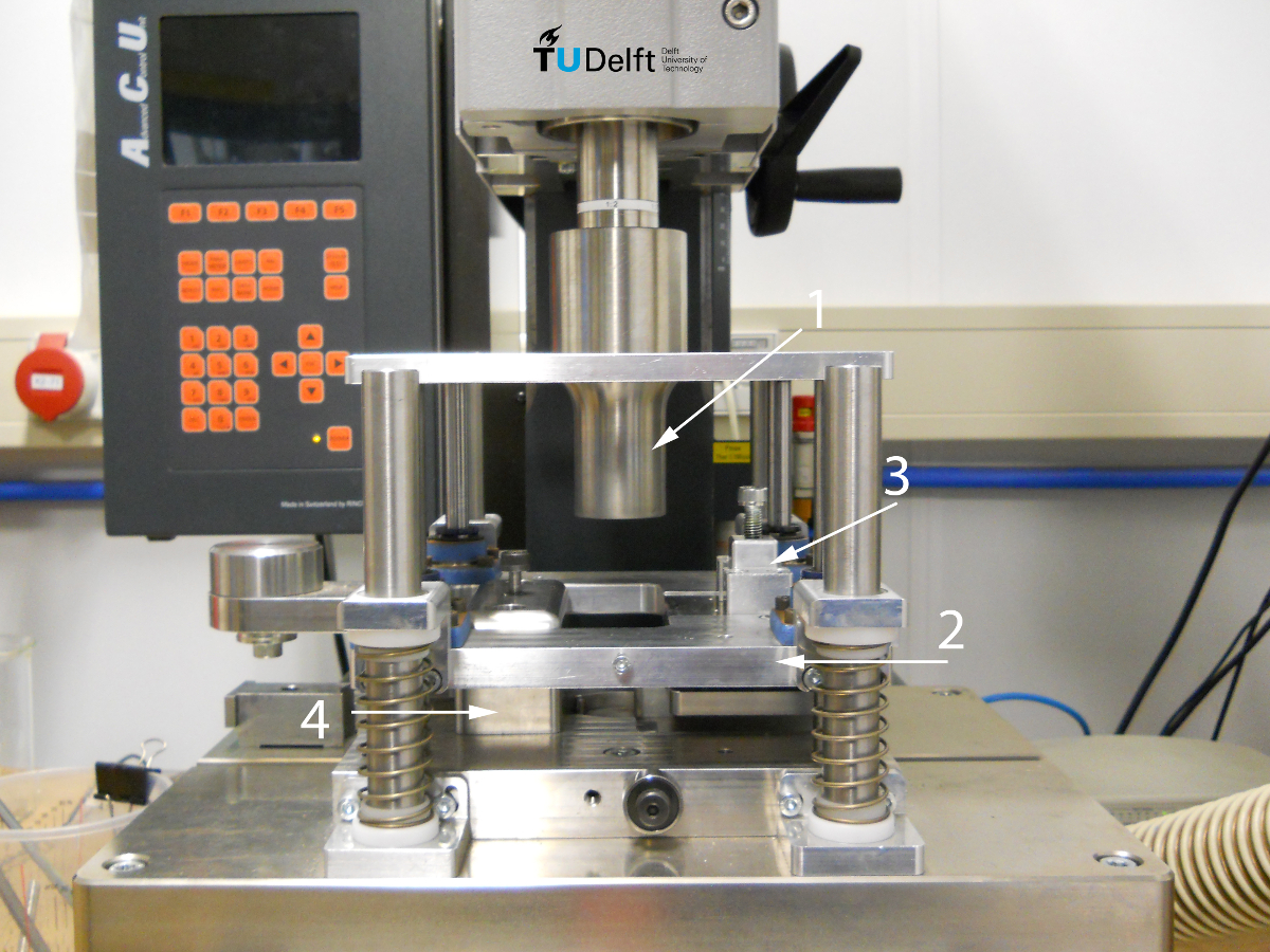
Note: A micro-processor controlled ultrasonic welder able to weld at constant amplitude is used in this step. The welder outputs process data, such as dissipated power and displacement of the sonotrode versus time to data acquisition software in a computer. A custom-built jig designed and manufactured to accurately position and clamp single lap shear samples during ultrasonic welding is used in this step (see Figure 1).

Figure 1. Ultrasonic welder and custom-built welding setup used in this study. 1: sonotrode, 2: sliding platform, 3: clamp for the upper specimen (attached to 2), and 4: clamp for the lower specimen (Reprinted from reference 4 with permission from Elsevier.) Please click here to view a larger version of this figure.
- Fill out a logbook sheet before each welding experiment.
- Take note of the following parameters: RT and humidity, welding setup reference, sonotrode type, sample number and materials, width and thickness of top and bottom samples, and thickness of the energy director.
- Turn on the ultrasonic welder and computer. Start the data acquisition software and open a new session.
- If not already in place, change the sonotrode to a cylindrical sonotrode with a diameter of 40 mm so that its bottom surface completely covers the welding area.
Note: A different shape of sonotrode can be used, but its bottom surface should not be smaller than the welding area. - Position and fixate specimens and energy director into the welding jig (see Figure 1).
- Attach a flat energy director to the bottom specimen with adhesive tape so that it covers a slightly larger area than the area to be welded (12.7 mm x 25.4 mm).
- Place the bottom sample into the jig and clamp it by tightening the top screw.
- Tape the other end of the energy director to the base of the setup so that it stays in place during the process.
- Place the upper sample into the clamp, align it and tighten the top screw.
- Position the clamp for the top sample into the sliding platform and tighten both screws.
- Before proceeding further, tighten all four screws once more.
- Determine the optimum duration of the vibration phase based on the displacement of the sonotrode to achieve the highest weld strength, as described in steps 2.5.1 to 2.5.8.
Note: An optimum duration of the vibration phase is determined for each desired combination of welding force and vibration amplitude.- Set the ultrasonic welder to differential displacement-control mode.
- Input welding force and vibration amplitude into the ultrasonic welder (for example, 300 N and 86.2 μm).
Note: For this ultrasonic welder, 86.2 μm corresponds to the peak-to-peak vibration amplitude. In the machine settings, it is expressed as half this value, 43.1 μm. - Input the sonotrode displacement, or travel, at the end of the vibration phase as a value equal to the initial thickness of the energy director (for example, 0.25 mm).
- Input solidification force and time into the ultrasonic welder (for example, 1,000 N and 4,000 msec).
- When ready, put on soundproof headphones and start the ultrasonic welding process.
- After the completion of the process, take note of the following output parameters: welding distance, maximum power, vibration time and energy. Remove the coupon from the welding setup and write its identification number on both ends with a paint marker.
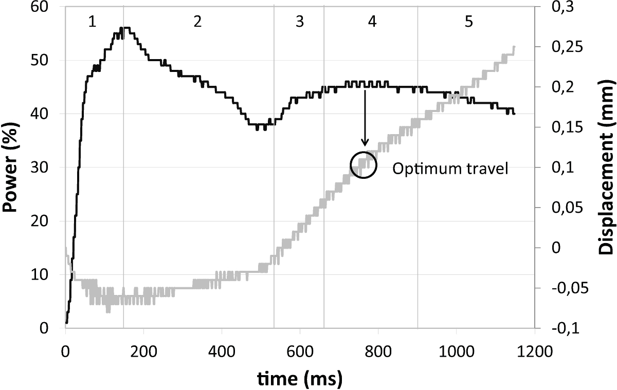
- Export the welding data (power and displacement of the sonotrode) to a spreadsheet and plot the power and displacement versus time curves during the vibration phase of the process.
Note: The displacement curve should plot the downward displacement of the sonotrode relative to its position at the onset of the vibration phase. - Identify the displacement in the middle of the power plateau (stage 4) as shown on Figure 2 (in this case, 0.10 mm).
Note: This particular displacement value is the optimum travel that controls the duration of the vibration phase and will be used in every subsequent weld for the same welding force and amplitude.

Figure 2. Power (black) and displacement (grey) curves for the ultrasonic welding process indicating optimum travel value. The vibration phase of the ultrasonic welding can be divided in 5 stages. Optimum travel value is located within stage 4. Study case: carbon fiber reinforced polyetherimide -PEI substrates, 0.25 mm-thick flat PEI energy director, 300 N welding force, 86.2 µm vibration amplitude, 0.25 mm travel. (Reprinted from reference 4 with permission from Elsevier.) Please click here to view a larger version of this figure.
- Weld coupons at the optimum travel value for the given welding force and amplitude combination.
- Repeat steps 2.1 to 2.5.6 for each weld. In step 2.5.3, use the optimum travel determined in step 2.5.8 for the corresponding welding force and amplitude combination.
Note: All LSS tests are carried out following ASTM D 1002 on a universal testing machine with a crosshead speed of 1.3 mm/min.
- Repeat steps 2.1 to 2.5.6 for each weld. In step 2.5.3, use the optimum travel determined in step 2.5.8 for the corresponding welding force and amplitude combination.
3. Single Lap Shear Strength (LSS) Testing of Welded Coupons
- Measure and take note of the width of the overlap for each welded coupon.
- Turn on the universal testing machine and open the testing procedure for LSS on the computer.
- In the testing interface, enter the sample number and dimensions of the overlap. Set the force to 0 and the grip-to-grip separation to its initial position (for example, 60 mm).
- Position the sample in the grips of the testing machine as shown on Figure 3.

Figure 3. Schematic view of the clamping in the Zwick/Roell 250 kN universal testing machine (not to scale). The offset displacement between the top and lower grips allows aligning the load direction with the center weld line to minimize bending during the lap shear strength test. Please click here to view a larger version of this figure.
- Start the testing procedure from the computer by clicking the "Start" button.
- After the sample breaks, remove it from the grips and secure both parts together with tape.
- Repeat steps 3.3 to 3.6 for all other samples.
- When the tests are completed, export the data to a spreadsheet and calculate the average LSS value, according to the procedure described in the standard, for each welding force and amplitude combination.
Results
Carbon fiber reinforced polyetherimide (CF/PEI) samples were welded following the method described in this paper. The samples were obtained from a composite laminate made out of five-harness satin fabric CF/PEI, with (0/90)3S stacking sequence and 1.92 mm nominal thickness. Samples were cut from this laminate so that the main apparent orientation of the fibers was parallel to their longest side. Flat PEI energy directors with 0.25 mm thickness were used. Both the composite samp...
Discussion
The results presented in the previous section indicate the appropriateness of the straightforward method proposed in this paper for ultrasonic welding of thermoplastic composite single lap coupons for the purpose of mechanical testing. The following paragraphs discuss how the results validate the three main pillars of the method, i.e., use of flat loose energy directors, use of process feedback to define optimum duration of the vibration and use of displacement control, as well as the applicability and limitatio...
Disclosures
The authors declare that they have no competing financial interest.
Acknowledgements
The authors would like to acknowledge the support of Ten Cate Advanced Materials in the form of free material supply to the work described in this paper.
Materials
| Name | Company | Catalog Number | Comments |
| Material/Reagent | |||
| Cetex carbon fiber / polyetherimide (CF/PEI) 5 harness satin prepreg | TenCate Advanced Composites (www.tencate.com) | Contact vendor | Material used in this study for the specimens. |
| PFQD solvent degreaser | PT Technologies Europe (now Socomore - www.socomore.com) | Contact vendor | Solvent degreaser for cleaning the specimens and energy directors. |
| Cotton cloths | For general cleaning purposes. No specific vendor was used. | ||
| 0.25 mm PEI film | TenCate Advanced Composites (www.tencate.com) | Contact vendor | Thin film used as energy director. |
| Adhesive tape | Airtech Advanced Materials Group (www.airtechintl.com) | 1" x 72 yds MFG # 327402 Contact vendor for catalog number | Used to attach energy director to bottom sample for ultrasonic welding. |
| Name | Company | Catalog Number | Comments |
| Equipment | |||
| Vötsch oven | Vötsch Industrietechnik (www.voetsch-ovens.com) | VTU 60/60 - Contact vendor for specific catalog number | Oven used to dry PEI film (energy directors) and PEI specimens before welding. |
| Rinco Dynamic 3000 ultrasonic welder | Aeson BV (www.aeson.nl/en/) | Contact vendor | 20 kHz ultrasonic welding machine used for the welding experiments. Several sonotrode sizes available. Contact vendor for details. ACUCapture software included. |
| Zwick/Roell universal testing machine | Zwick (www.zwick.com) | Z250 - Contact vendor for specific catalog number | Universal testing machine with maximum load of 250 kN used for single lap shear strength measurements. |
References
- Yousefpour, A., Hojjati, M., Immarigeon, J. P. Fusion bonding/welding of thermoplastic composites. J Thermoplast Compos. 17, 303-341 (2004).
- Villegas, I. F. In situ monitoring of ultrasonic welding of thermoplastic composites through power and displacement data. J Thermoplast Compos. 28 (1), 66-85 (2015).
- Benatar, A., Gutowski, T. G. Ultrasonic welding of PEEK Graphite APC-2 composites. Polym Eng Sci. 29 (23), 1705-1721 (1989).
- Villegas, I. F. Strength development versus process data in ultrasonic welding of thermoplastic composites with flat energy directors and its application to the definition of optimum processing parameters. Compos Part A-Appl S. 65, 27-37 (2014).
- Lu, H. M., Benatar, A., He, F. G. Sequential ultrasonic welding of PEEK/graphite composite plates. Proceedings of the ANTEC'91 Conference. , 2523-2526 (1991).
- Potente, H. Ultrasonic welding - principles & theory. Mater Design. 5, 228-234 (1984).
- Stavrov, D., Bersee, H. E. N. Resistance welding of thermoplastic composites - an overview. Compos Part A-Appl S. 36, 39-54 (2005).
- Villegas, I. F., Valle-Grande, B., Bersee, H. E. N., Benedictus, R. A comparative evaluation between flat and traditional energy directors for ultrasonic welding of CF/PPS thermoplastic composites. Compos Interface. , (2015).
- Levy, A., Le Corre, S., Villegas, I. F. Modelling the heating phenomena in ultrasonic welding of thermoplastic composites with flat energy directors. J Mater Process Tech. , 1361-1371 (2014).
- Shi, H., Villegas, I. F., Bersee, H. E. N. Strength and failure modes in resistance welded thermoplastic composite joints: effect of fibre-matrix adhesion and fibre orientation. Compos Part A-Appl S. 55, 1-10 (2013).
- Villegas, I. F., Bersee, H. E. N. Ultrasonic welding of advanced thermoplastic composites. An investigation on energy-directing surfaces. Adv Polym Tech. 29 (2), 113-121 (2010).
- Harras, B. K., Cole, C., Vu-Khanh, T. Optimization of the ultrasonic welding of PEEK-carbon composites. J Reinf Plast Comp. 15 (2), 174-182 (1996).
Reprints and Permissions
Request permission to reuse the text or figures of this JoVE article
Request PermissionThis article has been published
Video Coming Soon
Copyright © 2025 MyJoVE Corporation. All rights reserved