
Aby wyświetlić tę treść, wymagana jest subskrypcja JoVE. Zaloguj się lub rozpocznij bezpłatny okres próbny.
Method Article
Controlled Strain of 3D Hydrogels under Live Microscopy Imaging
W tym Artykule
Podsumowanie
The presented method involves uniaxial stretching of 3D soft hydrogels embedded in silicone rubber while allowing live confocal microscopy. Characterization of the external and internal hydrogel strains as well as fiber alignment are demonstrated. The device and protocol developed can assess the response of cells to various strain regimes.
Streszczenie
External forces are an important factor in tissue formation, development, and maintenance. The effects of these forces are often studied using specialized in vitro stretching methods. Various available systems use 2D substrate-based stretchers, while the accessibility of 3D techniques to strain soft hydrogels, is more restricted. Here, we describe a method that allows external stretching of soft hydrogels from their circumference, using an elastic silicone strip as the sample carrier. The stretching system utilized in this protocol is constructed from 3D-printed parts and low-cost electronics, making it simple and easy to replicate in other labs. The experimental process begins with polymerizing thick (>100 μm) soft fibrin hydrogels (Elastic Modulus of ~100 Pa) in a cut-out at the center of a silicone strip. Silicone-gel constructs are then attached to the printed-stretching device and placed on the confocal microscope stage. Under live microscopy the stretching device is activated, and the gels are imaged at various stretch magnitudes. Image processing is then used to quantify the resulting gel deformations, demonstrating relatively homogenous strains and fiber alignment throughout the gel’s 3D thickness (Z-axis). Advantages of this method include the ability to strain extremely soft hydrogels in 3D while executing in situ microscopy, and the freedom to manipulate the geometry and size of the sample according to the user’s needs. Additionally, with proper adaptation, this method can be used to stretch other types of hydrogels (e.g., collagen, polyacrylamide or polyethylene glycol) and can allow for analysis of cells and tissue response to external forces under more biomimetic 3D conditions.
Wprowadzenie
Tissue response to mechanical forces is an integral part of a wide range of biological functions, including gene expression1, cell differentiation2, and tissue remodeling3. Moreover, force-induced changes in the extracellular matrix (ECM) such as fiber alignment and densification can impact cell behavior and tissue formation4,5,6. The ECM’s fibrous mesh structure has intriguing mechanical properties, such as non-linear elasticity, non-affine deformation and plastic deformations7,8,9,10,11,12. These properties impact how cells and their surrounding microenvironment respond to external mechanical forces13,14. Understanding how the ECM and tissues respond to mechanical forces will enable progress in the field of tissue engineering and in the development of more accurate computational and theoretical models.
Most common methods to mechanically stretch samples have focused on cell-laden 2D substrates to explore the effects on cell behavior. These include, for example, applying strain to polydimethylsiloxane (PDMS) substrates and analyzing cell reorientation angles in relation to the stretch direction15,16,17,18,19. Yet, methods investigating the response of 3D cell-embedded hydrogels to external stretch, a situation that more closely mimics tissue microenvironment, are more limited. Advances toward 3D stretching methods are of particular importance because cells behave differently on 2D substrates when compared to 3D matrices20. These behaviors include cellular realignment, protein expression levels, and migration patterns21,22,23.
Methods and devices that allow for 3D sample stretching include both commercially available24,25,26,27,28 and those developed for laboratory research29. These methods use distensible silicone tubes30, multi-well chambers31, clamps26,32, bioreactors11,33, cantilevers34,35,36, and magnets37,38. Some techniques generate stretch that locally deforms 3D hydrogels, for example by pulling needles from two single points in the gel5, while others allow for deformation of the entire bulk of the gel16. Moreover, most of these systems focus on analysis of the strain field in the X-Y plane, with limited information on the strain field in the Z-direction. Additionally, only a handful of these devices are capable of microscopic in situ imaging. The main challenge with in situ high-magnification imaging (e.g., confocal microscope) is the limited working distance of a few hundred microns from the objective lens to the sample. Devices that do allow live imaging during stretch sacrifice the uniformity of strain in the Z-axis or are relatively complex and difficult to reproduce in other laboratories39,40.
This approach to stretch 3D hydrogels allows for static or cyclical uniaxial strain during live confocal microscopy. The stretching device (referred to as ‘Smart Cyclic Uniaxial Stretcher – SCyUS’) is constructed using 3D printed parts and low-cost hardware, allowing easy reproduction in other labs. Attached to the device is a commercially available silicone rubber with a geometric cut-out in its center. Hydrogel components are polymerized to fill the cut-out. During polymerization, biological hydrogels, such as fibrin or collagen, naturally adhere to the interior walls of the cut-out. Using the SCyUS, the silicone strip is uniaxially stretched, transferring controlled strains to the embedded 3D hydrogel41.
This system allows for a unique combination of features and advantages compared to other existing methods. First, the system allows uniaxial stretching of thick 3D soft hydrogels (>100 µm thick, <1 kPa stiffness) from their periphery, with Z-homogenous deformation throughout the hydrogel. These hydrogels are too soft to be gripped and stretched by conventional tensile techniques. Second, the stretching device can be easily replicated in other labs since 3D printing is readily available to researchers and the electronics used in the design are low-cost. Third, and perhaps the most attractive feature, the geometry and the size of the cut-out in the silicone strip can be easily manipulated, allowing for tunable strain gradients and boundary conditions as well as the use of a variety of sample volumes, down to a few microliters.
The presented protocol consists of molding fibrin gel into ~2 mm diameter disks in 0.5 mm thick silicone rubber strips proceeded by uniaxial stretch under live confocal microscopy. The following discusses in detail the experimental procedures for measuring and analyzing the strains acting on the geometric cut-out, the internal strains developed in the hydrogel, as well as resulting fiber alignment after various stretch manipulations. Finally, the possibility of embedding cells in the hydrogel and exposing them to controlled external stretch is discussed.
Access restricted. Please log in or start a trial to view this content.
Protokół
1. Solution preparation (to be performed in advance)
- Fibrinogen labeling
NOTE: The labeling step is required only if analyzing the deformation of the fibrin gel is desired. For cellular experiments, it is possible to use an unlabeled gel.- Add 38 μL of 10 mg/mL succinimidyl ester fluorescent dye (dissolved in DMSO) to 1.5 mL of 15 mg/mL fibrinogen solution (molar ratio of 5:1) in a 50 mL centrifuge tube and place on a shaker for 1 hour at room temperature. Afterwards, place the tube in the centrifuge for 3 minutes at 800 x g (room temperature).
- Filter the supernatant from the previous step through a desalting column packed with dextran gel resin (Table of Materials) to separate the unreacted dye,42 by following these steps.
- Pre-wash the column with 25 mL of fibrinogen buffer.
- Slowly inject the labeled-fibrinogen from step 1.1.1 into the column, making sure that there are no bubbles entering the filter. Discard the first ~0.3 mL of eluted solution (4-6 drops of faint colored liquid). Then collect the following 1.0-1.5 mL of purified solution (follow manufacturer’s protocol for more specific details).
- Finish the filtration process by sterilizing the resulting purified solution using a syringe-driven filter (0.22-0.45 μm).
- To clean and recycle the column, wash with 20 mL of fibrinogen buffer, and then store in 25 mL of 20% ethanol.
- After elution, divide the resulting purified labeled-fibrinogen into small aliquots of ~7-50 μL, depending on the desired number of stretched gels. For each stretched 2 mm diameter circle gel, prepare about 3.5 μL of fibrinogen (2.5 μL will be used per gel + 1 μL for pipetting errors).
- Store the aliquots in a -20 °C freezer. They can be used up to about one year (it is not recommended to thaw and freeze again).
- For the remainder of this protocol, keep approximately 7 μL of the purified labeled fibrinogen in the refrigerator (4 °C) until step 4. This volume is intended for the creation of two stretched gels (2.5 μL is needed per gel, and an extra volume of 1 μL is used to account for errors in sample preparation).
NOTE: This filtering procedure typically dilutes the initial 15 mg/mL fibrinogen solution to a final concentration of about 10 mg/mL. The dilution factor depends on the initial volume and concentration of fibrinogen, as specified in the manufacturer's protocol.
- Prepare 7 μL of thrombin solution (dilute using thrombin buffer to 2 units/mL, Table of Materials) and keep in the refrigerator (4 °C) until step 4. This volume is intended to fill the cut-outs of two stretched gels.
NOTE: In order to perform internal strain analysis, 1 µm diameter fluorescent spherical beads (purchased as a suspension [2% solids] in water plus 2 mM NaN3) should be added to the thrombin solution (a ratio of 1:25 v/v % of bead:thrombin is recommended for a 40x objective). Beads should be included only when internal strain measurements are desired, either in the presence or absence of cells.
2. Silicone strip preparation
- Retrieve the 0.5 mm thick silicone rubber and cut it into 15 x 80 mm2 strips with a 2 mm diameter hole in the center of the strip (Figure 1). If possible, use a programmable laser cutter for high precision. If programmable machinery is not available, scissors are sufficient for cutting the strip outline and a small hole-punch is adequate for the center cut-out.
NOTE: Commercial silicone rubber is usually purchased with plastic wrap on both sides. Keep original plastic covering on both sides of the silicone if possible. If reusing silicone strips from a previous experiment, treat them with trypsin for 0.5 hour, soak in 0.2 M NaOH for 0.5 hour, and then soak in 70% ethanol for 1 hour. Let them dry before use. - Prepare sealing film (hydrophobic) layers with dimensions of at least 20 × 30 mm2, so they are wider than the silicone strip and thus allowing for a seal to form over the entire geometric cut-out.
- Wash a 10 cm dish with 70% ethanol, and then wipe and dry with non-linting delicate task wipes (for both sterile and non-sterile experiments). This step is important since it allows the sealing film layers to better stick to the plate and restrict sample’s movement during the preparation process.
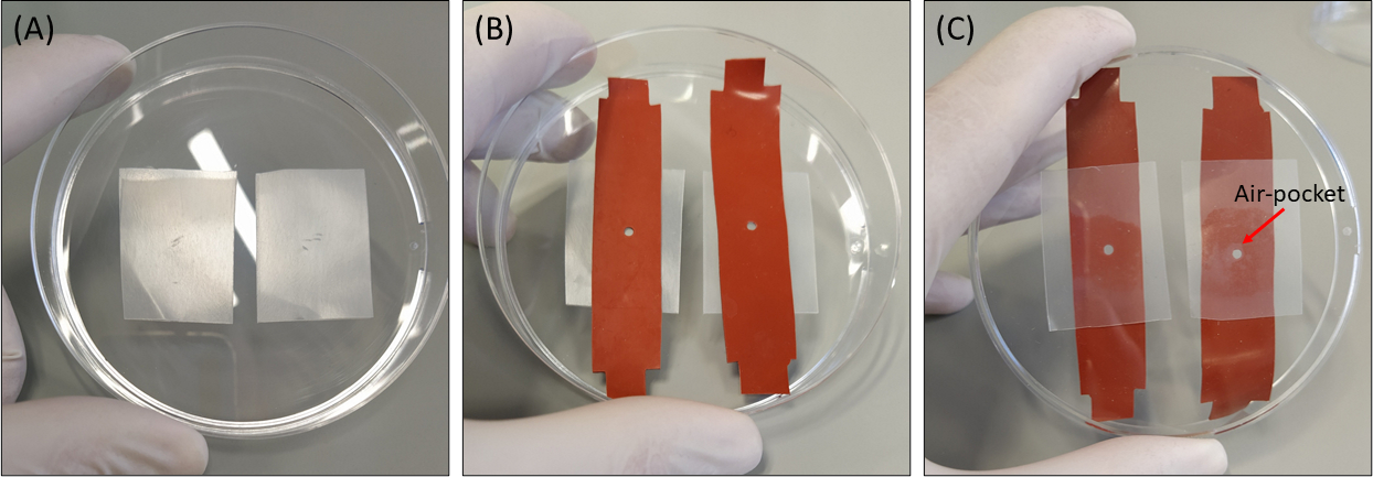
- Place the sealing film layers in the washed 10 cm dish so there is enough space to place two strips in each dish side-by-side (Figure 2A).
- Remove the plastic wrap from one side of the silicone strip and place the exposed side on the sealing film layer so the cut-out is surrounded entirely by the sealing film layer (Figure 2B). Then, press gently on the silicone against the sealing film layer in order to seal the area surrounding the cut-out, using clean gloved fingers.
NOTE: Ensure there are no air-pockets between the silicone and the sealing film, especially around the cut-out. Do this by examining the bottom-side of the dish (Figure 2C).
- Remove the plastic wrap from one side of the silicone strip and place the exposed side on the sealing film layer so the cut-out is surrounded entirely by the sealing film layer (Figure 2B). Then, press gently on the silicone against the sealing film layer in order to seal the area surrounding the cut-out, using clean gloved fingers.

Figure 1: Hydrogel straining approach. (A) 15 × 80 mm2 silicone strip with a 2 mm diameter cut-out in the center of the strip (B) A silicone strip with a circular cut-out with embedded fibrin gel. For illustrative purposes, the cut-out in the silicone is larger than in the actual experiments (C) Schematic of the stretching approach with the silicone strip (orange), circular gel (cut-out in the middle), and fabric extenders (green) that connect the silicone to the stretching device. Enlarged area of the gel indicates the deformation of the gel, in response to uniaxial stretching of the silicone. For simplicity, the compression along the thickness of the gel (Z-axis) is not shown in the illustration. Figures 1B & 1C have been adapted from Roitblat Riba et al.41 Please click here to view a larger version of this figure.

Figure 2: Example of proper placement of a silicone strip on a sealing film layer prior to gel polymerization. (A) Placement of two sealing film layers in a 10 cm dish (B) Placement of silicone strips on the sealing film layers (C) Bottom-view of the dish, displaying the air-seal between the silicone and the sealing film layer. Left: Proper seal of the sealing film layer to the silicone strip around the cut-out without air-pockets. Right: Improper seal of the sealing film layer to the silicone strip cut-out with air-pockets around the edge of the cut-out. This will lead to leaking of the hydrogel components underneath the silicone. Red arrow points to an area where an air-pocket was formed. Please click here to view a larger version of this figure.
3. Preparing thrombin with cells
NOTE: Perform this step only if embedding cells in the hydrogel is desired, and under sterile conditions in a biological hood (Table of Materials).
- Sterilization: the day prior to the cellular experiment, place the silicone strips & sealing film layers in 70% ethanol overnight and then perform UV sterilization for 30 minutes on each side (if the 10 cm dishes are not already sterile, they should also be sterilized under UV light for 30 minutes after a 70% ethanol wash). The UV system utilized in the protocol is the one built into the biological hood.
NOTE: Alternatively, an autoclave sterilization cycle (140 °C) can be performed on the silicone strips since they are resistant to up to 260 °C. - Perform a cell count to determine cell concentration, and then centrifuge and re-suspend the cell pellet with 7 μL of thrombin (2 units/mL) in a 1.5 mL centrifuge tube. We recommend a cell concentration of 800 cells/μL of thrombin. Keep the cells chilled until use (do not exceed more than half an hour to avoid damaging the cells).
4. Polymerization of fibrin gels
- Retrieve the 2 Unit/mL thrombin & 10 mg/mL labeled-fibrinogen solutions from the refrigerator (prepared in step 1) and place them on ice where they will be accessible.
NOTE: Solutions are kept cold prior to the mixing process in order to slow down the polymerization reaction kinetics. This allows for more homogenous mixing of the proteins. - With the dish(es) set up (step 2), extract 2.5 μL of labeled-fibrinogen and pipette it uniformly into the silicone cut-out (with the sealing film layer attached to its bottom side) so that the entire circumference of the cut-out is in contact with fibrinogen. Be careful not to allow any air-pockets or bubbles to form anywhere in the solution, paying particular attention to the bottom edges of the cut-out (the interface between the sealing film layer and silicone).
- Immediately take 2.5 μL of thrombin (with or without cells/beads) and pipette it directly into the fibrinogen solution in the cut-out (reaching final volume of 5 μL fibrin). Then quickly mix the two solutions by carefully pipetting up and down ~10 times. During the mixing process, move the tip around the entire volume to create as homogenous a solution as possible.
- Add a very small amount of Phosphate Buffer Saline (PBS) [alternatively cell medium for cell experiments, Table of Materials] along the edge of each dish so the hydrogel does not dry out during the polymerization process. Ensure there is no contact between the PBS/cell medium and the samples as this will damage the sample.
- Cover the dish(es) and place them in the incubator at 37 °C for 30 minutes.
NOTE: The required incubation time is dependent on the volume of the gel. If larger volumes are used, the incubation time should increase. - Remove the dish(es) from the incubator and add PBS/cell medium to the dish, submerging the entire gel-silicone construct.
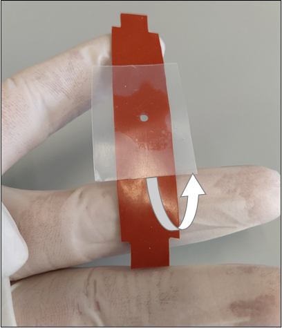
- Carefully lift the sample constructs one at a time from the dish making sure the sealing film layer remains adhered to the strip. Slowly detach the sealing film layer from the silicone by gently pealing from one end of the silicone to the other (Figure 3). Avoid pulling from areas close to the cut-out where stress concentrations may exist (this is mainly important for non-circular geometries). Avoid any contact with the cut-out as it will damage the sample.
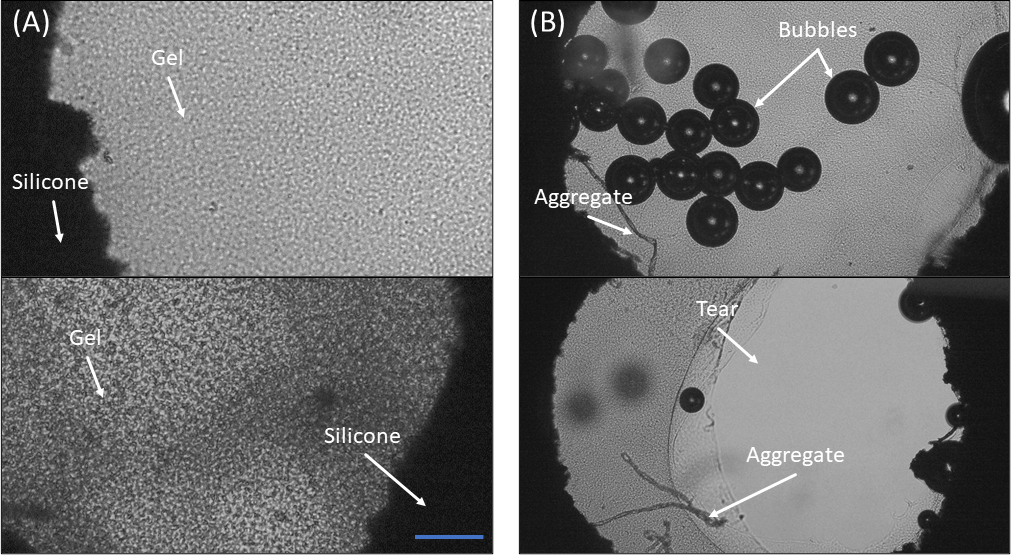
- Place the strip back into the dish with PBS/cell medium such that the strip is floating in the dish. Then take the dish(es) to a standard cell-culture microscope to qualitatively assess the condition of each sample. Gels must be uniform, continuous throughout the cut-out, and no bubbles should be present. Using Figure 4 as a guide, select the best samples for further analysis.

Figure 3: Proper removal of the sealing film layer from the bottom of the silicone strip. The removal process should be done slowly so the hydrogel will not tear or break its adhesion with the inner walls of the cut-out. The white arrow shows the direction of removal. Please click here to view a larger version of this figure.

Figure 4: Microscopic observation of fibrin gels in the silicone cut-out. (A) Two examples of a properly polymerized fibrin gel. Notice the relative homogeneity of the gel and the full adhesion to the edges of the cut-out (B) Two examples of sample polymerization failure. Top: Notice the many bubbles and the aggregates formed on the bottom left side. Bottom: Notice the tearing of the gel from the cut-out edges and the aggregates in the bottom left region of the cut-out. Scale bar = 300 μm Please click here to view a larger version of this figure.
5. Sample loading on the SCyUS device
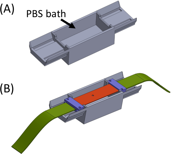
- Fill the bath with PBS/cell medium (Figure 5) and place the silicone strip carrying the sample gel across the top so the ends are sitting on each side of the bath. The bath is meant to avoid any drying of the gel. Place and tighten the clamps (purple) along with the fabric strips (green) so that all pieces are connected to form one straight strip with the cut-out in the center (Figure 5).
- Retrieve the SCyUS device and attach the aluminum liquid well and 22 mm x 40 mm rectangular glass coverslip (No. 1 or 1.5) (Figure 6Aiii). Attach the cover slip to the bottom of the well using sealing material (e.g., vacuum grease) so that the well can be filled with liquid without leakage.
- Fill the well with ~1-2 mL of PBS/cell medium and place the strip + fabric + gel construct (Figure 6B) into the device. Clamp the fabric strip (2) into the bracket (1) so that the cut-out + gel (5) is in the center as shown, then carefully place the pin-down insert (4) into the device and lock it in place.
- Next, insert the other fabric side to the spindle (without attaching the servomotor) and lock it into the spindle (Figure 6C).
- Insert the SCyUS device with the attached sample into the stage of the microscope (Figure 6C). Connect the microcontroller (Table of Materials) to the computer via a USB cable and connect the servomotor to the microcontroller. Open the SCyUS control module on the computer. The sample is now ready for imaging to check the adequacy of the gel’s thickness and fiber homogeneity under the confocal microscope.

Figure 5: (A) Jig containing a PBS bath (3D printed) (B) Strip placement on the jig to ensure proper in-line attachment of brackets (in purple) and preventing drying of the gel. This figure has been modified with permission from Roitblat Riba et al.41 Please click here to view a larger version of this figure.

Figure 6: SCyUS stretching device. (A) Several views of a CAD model of the main parts of the SCyUS: spindle connected to the servo (blue), static anchor (red), insert that pins the silicone strip down (purple) and fixers that prevent the insert from rising up (yellow-green). A top view of the system (Ai), a cut view of the system (Aii) showing the path of the strip (orange line), and a bottom view (Aiii) of the aluminum liquid well with a glass coverslip. The liquid well can be moved up and down with the turn of a screw fitted into the major threading. The upward movement of the aluminum well is limited by the purple insert’s side wings, as shown by the white arrows (B) The actual system: (1) static anchor (2) green non-stretchable fabric (3) screw for aluminum liquid well height control (4) red pin-down insert (5) a silicone strip with a circular cut-out (6) blue connecting clamps (C) The stretching system placed on a confocal microscope. The servomotor and the spindle are shown with arrows. This figure has been modified with permission from Roitblat Riba et al.41 Please click here to view a larger version of this figure.
6. Ensure adequate gel for sampling
- Using the confocal microscope (Table of Materials) take a low-magnification (10×), low-resolution (~1.4 μm x 1.4 μm pixel size) confocal Z-stack (≤10 Z-slices with a step size of approximately 10 μm is sufficient) tile image of the entire gel using lasers of 488/543/561 to examine homogeneity and adhesion to the circumference of the geometric cut-out throughout the thickness of the silicone (Figure 7A-B). Use this Z-stack image as a map for the following steps.
- Using low-resolution live imaging, scan the gel and determine the lowest Z-position where full adhesion to the inner walls of the cut-out is apparent with no tears or bubbles and note the Z-location of the microscope (Zl). To determine full adhesion of the gel to the silicone throughout its circumference, scan the interface of the fluorescent label of the gel and the silicone strip (dark background) under the microscope (Figure 7C).
- Move up in the Z-direction until there is no longer continuity in the gel and note the Z-position (Zu):
- Subtract the upper limit (Zu) of the Z-direction from the lower limit (Zl). This is the reference thickness of the sample (Zo):

If Zo ≥ 100 μm then the gel is considered satisfactory for analysis. Note that the thickness of the silicone cut-out is about 500 μm, but gel polymerization in the cut-out typically results in a smaller gel thickness. 100 μm is the minimum recommended thickness to ensure a stable stretching process, without tears or detachment of the gel from the silicone cut-out.
NOTE: At different XY locations, the thickness of the gel can vary. This section of the protocol measures the minimum thickness of the gel, allowing us to determine the gel quality and indicate if it is sufficient for stretching. Additionally, finding the center of the gel provides a reference point to return to post-stretching, whether static or dynamic.

Figure 7: Gel homogeneity. Tile images were captured and stitched using the confocal microscope software (Table of Materials) (A) A single stitched tile Z-slice image of a fibrin gel sample with relatively inhomogeneous fiber density due to improper thrombin and fibrinogen mixing pre-polymerization. This gel will not provide a reliable analysis (B) A single stitched tile Z-slice image of a fibrin gel sample with relatively homogenous fiber density. This is an acceptable gel for stretching experiments. Scale bar for images A & B is 200 μm (C) Zoom in of the interface between the fluorescently labeled gel (red) and the silicone (black background). Scale bar = 100 μm. Please click here to view a larger version of this figure.
7. SCyUS operation, stretching & imaging
- Now that the sample has been determined to be of satisfactory quality and is set on the SCyUS device properly, determine the pre-stretched position of the sample. This is achieved by using live imaging under the confocal microscope (similar to step 6.2).
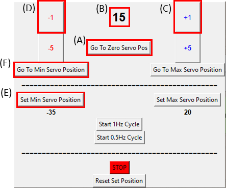
- Make sure the servomotor is at its zero position by clicking the Go To Zero Servo Pos button (Click on Figure 8A and ensure that Figure 8B displays zero) and attach it to the stretching device as seen in Figure 6C.
NOTE: Do this step slowly and carefully as not to put any excess tension on the sample. - While imaging the sample, move the motor one degree (Figure 8C) at a time in the clockwise direction by clicking the +1 button until the right side of the cut-out is observed to move. Then, reverse the movement (Figure 8D) back to the penultimate step position by clicking on the -1 button. This verifies that the sample is under minimal tension. Click on the Set Min Servo Position button (Figure 8E) to set the reference position. It is possible to return to the reference position at any time by clicking the Go To Min Servo Position button (Figure 8F).
NOTE: It is recommended to use a high-magnification objective (≥40×) for this step to minimize error. - Capture a high-magnification (40×), high-resolution (~0.2 μm × 0.2 μm pixel size), single Z-slice tile image of the entire gel area. This will be used as the reference image for post-processing analysis. It is recommended to capture a single Z-slice image in the middle of the gel thickness (by using Zo from Eq. 1), this will allow for the return to approximately the same Z-position after stretching. Also, take into consideration that high-resolution tile images of the entire gel area take considerable time (~20-30 min).
- Now the sample is ready for static stretching. Adjust the servomotor to the desired stretch magnitude by advancing one degree (Figure 8C) at a time in the GUI (perform this slowly, about 1 degree/second).
- Make sure the servomotor is at its zero position by clicking the Go To Zero Servo Pos button (Click on Figure 8A and ensure that Figure 8B displays zero) and attach it to the stretching device as seen in Figure 6C.
- At each stretch magnitude where analysis is desired, capture a single Z-slice high-resolution tile image of the entire gel area for post-processing analysis. Similar to step 6.2, verify that the gel has not detached from the silicone throughout its circumference by scanning the interface between the gel (red) and the silicone (dark background), looking for changes in the adhesion from the previous stretch magnitude.
NOTE: During the activation of the motor, use live imaging to follow the gel location in X-Y (with low-resolution, low-magnification settings). The gel experiences a Z-Poisson effect where the bottom of the gel rises, therefore the Z-position of the microscope should also be adjusted to the approximate center of the gel thickness for every stretch magnitude. This can be achieved by recalculating Zo (Eq. 1) for each stretch magnitude. Since stretch in the Z-direction is relatively homogenous, it is not critical to find the exact center depth of the gel.

Figure 8: GUI for the SCyUS control module. (A) Position of the motor in degrees. The value ranges from -90° to 90° (B) ‘Set Minimum Servo Position’. This button allows for a pre-set minimum position, for setting a new reference position that is different from the Zero Servo Position (C) ‘Plus 1°’ button moves the servo motor one-degree clockwise (D) ‘Minus 1°’ button moves the servo motor one-degree counter-clockwise (E) ‘Go to zero position’ button sets the servomotor position to 0° ([A] will be set to zero) (F) ‘Go to minimum servo position’ button moves the servomotor to the user defined ‘Min’ position. Please click here to view a larger version of this figure.
8. Post-processing external strain measurements
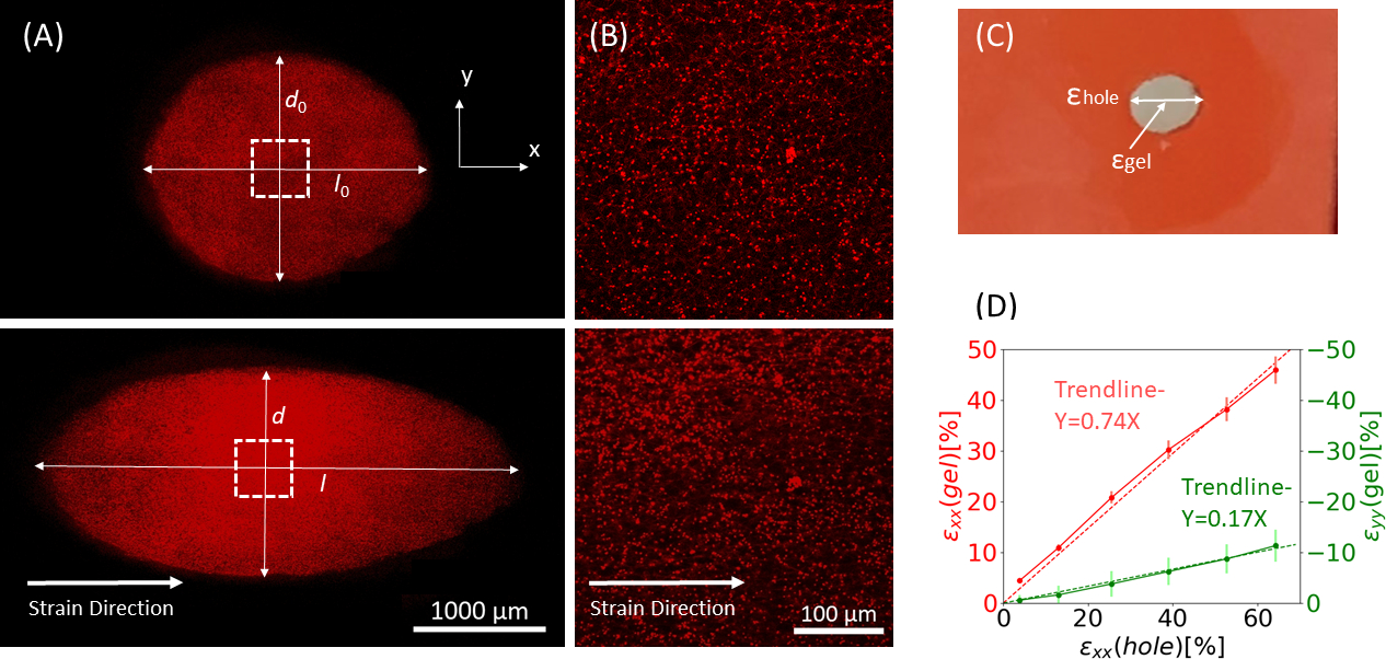
- To measure the effective strains of the cut-out boundaries, measure the edge-to-edge lengths in the stretch direction (X-axis) at the center of the Y-axis (Figure 9A).
- Upload the pre-stretch image to the image processing software (ImageJ FIJI43) and measure the largest-edge-to-edge distance which is defined as the axial length of the hole (
 ) at the center.
 - Define the largest distance from top to bottom as the perpendicular distance (
 ).
). - Repeat this process for all stretch interval images and calculate the axial (
 ) and perpendicular (
 ) distances of the cut-out periphery (Figure 9A, bottom) and then perform the following calculations to find the strains of the cut-out edges:
- Upload the pre-stretch image to the image processing software (ImageJ FIJI43) and measure the largest-edge-to-edge distance which is defined as the axial length of the hole (


Figure 9: Gel strains due to external stretching of the silicone strip. (A) X-Y cross-section of an un-stretched fibrin gel (top), and after application of εhole = 64% strain along the x direction (bottom). The gel is embedded with fluorescent beads. The relevant lengths of d and l used for calculation of εhole are indicated in the images (B) Zoom-in images of the dashed square area marked in A (C) Illustration of the strain types considered in this study: εhole is the axial strain of the cut-out at its maximum diameter, and εgel is the axial strain in the center of the gel (as measured by the bead aggregate locations) (D) A linear relationship was found between εhole and εgel in both xx direction (red line) and yy direction (green line). This figure has been adapted with permission from Roitblat Riba et al.41 Please click here to view a larger version of this figure.
9. Fiber orientation analysis
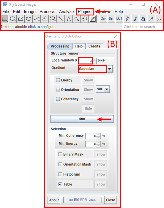
- Use quantification of fiber alignment to characterize the structural response of the fibrous gel to increasing magnitudes of stretch. Upload high-resolution images to ImageJ FIJI software (NIH)43 and then analyze using the OrientationJ (EPFL)44 module (Settings: Gaussian gradient, and 3-pixel window, Figure 10).
- Calculate the 2D Nematic Order Parameter (NOP) of the orientation histogram as:45

NOTE: A value of NOP = 1 indicates perfect alignment along the axial direction (angle zero) and NOP = 0 indicates isotropy. The orientation angle, θ, is the fiber angle in relation to the strain axis (x-axis) obtained through image analysis and precisely defined in the OrientationJ documentation.44
- Calculate the 2D Nematic Order Parameter (NOP) of the orientation histogram as:45

Figure 10: Fiber orientation analysis using FIJI ImageJ software. (A) Main Menu of ImageJ with an arrow indicating the location of the ‘Plugins’ pulldown menu where ‘OrientationJ’ can be found. Under the extended menu of ‘OrientationJ’, click on the ‘OrientationJ Distribution’ option (B) OrientationJ’s Distribution module. Set ‘Local window σ’ to 3 pixels and ‘Gradient’ to ‘Gaussian’. Then press the ‘Run’ button (red arrow). Please click here to view a larger version of this figure.
10. Manual internal gel strain analysis
- While performing live high-magnification imaging of a hydrogel with embedded beads, manually locate a region of interest (ROI) with easily recognizable features (e.g., aggregates of beads), in order to return to the same location after each stretch magnitude.
NOTE: Compression in the Z-direction (Poisson effect) can lead to an increase in bead density as stretch increases, therefore we suggest choosing bead aggregates large enough, so they are clearly identifiable. This protocol calls for the analysis of the central region of the fibrin gel, though any region can be chosen. - In the pre-stretch position (step 6), capture a high-resolution Z-stack image of the selected ROI. After each desired stretch interval, return to the same ROI and repeat the image capture process.
- Take the images and import them into ImageJ. In the ROI, record the X-Y pixel location of each visible bead aggregate. Transfer the recorded data to a spreadsheet.
- Measure the distances between every pair of aggregates and compare them to the distances of the same pairs in the reference image, allowing calculation of strains in the X and Y directions.
NOTE: If a continuous real-time movie is recorded while the gel is stretched (instead of static image capture), an automatic analysis of strains can be performed with digital image or volume correlations (DIC/DVC) methods, as previously demonstrated46,47. However, it should be noted that automatic DIC/DVC analysis is challenging in this setting, as the Z-stack is not only moving in the X-Y plane but also in the Z-direction due to the Poisson effect (compression), accounting for considerable drifts during the recorded movie.
Access restricted. Please log in or start a trial to view this content.
Wyniki
Representative data from static stretch of increasing magnitudes applied to the silicone strip carrying a 3D fibrin hydrogel, embedded with 1 μm fluorescent beads, is shown in Figure 9. The analysis demonstrates the effect of silicone stretch on geometric changes of the cut-out as well as the developed strains within the gel. Z-stack images of the entire gel are used to evaluate the deformation of the original circle shaped cut-out to the elliptical geometry (
Access restricted. Please log in or start a trial to view this content.
Dyskusje
The method and protocol presented herein are largely based on our previous study by Roitblat Riba et al.41 We include here the full computer-aided design (CAD), Python and microcontroller codes of the SCyUS device.
The major advantages of the presented method over existing approaches include the possibility to strain very soft 3D hydrogels (Elastic Modulus of ~100 Pa) from their circumference, and under live confocal imaging. Other methods are usually ...
Access restricted. Please log in or start a trial to view this content.
Ujawnienia
The authors have nothing to disclose.
Podziękowania
Some figures included here have been adapted by permission from the Copyright Clearance Center: Springer Nature, Annals of Biomedical Engineering. Straining 3D hydrogels with uniform z-axis strains while enabling live microscopy imaging, A. Roitblat Riba, S. Natan, A. Kolel, H. Rushkin, O. Tchaicheeyan, A. Lesman, Copyright© (2019).
https://doi.org/10.1007/s10439-019-02426-7
Access restricted. Please log in or start a trial to view this content.
Materiały
| Name | Company | Catalog Number | Comments |
| Alexa Fluor 546 carboxylic acid, succinimidyl ester | Invitrogen | A20002 | |
| Cell Medium (DMEM High Glucose) | Biological Industries | 01-052-1A | Add 10% FBS, 1% PNS, 1% L-Glutamine, 1% Sodium Pyruvate |
| Cover Slip #1.5 | Bar-Naor Ltd. | BN72204-30 | 22×40 mm |
| DIMETHYL SULPHOXIDE 99.5% GC DMSO | Sigma-Aldrich Inc. | D-5879-500 ML | |
| Dulbecco's Phosphate-Buffered Saline | Biological Industries | 02-023-1A | |
| EVICEL Fibrin Sealant (Human) | Omrix Biopharmaceuticals | 3902 | Fibrinogen: 70 mg/mL, Thrombin: 800-1200 IU/mL |
| Fibrinogen Buffer | N/A | Recipe for 1L: 7g NaCl, 2.94g trisodium citrate dihydrate, 9g glycine, 20g arginine hydrochloride & 0.15g calcium chloride dihydrate. Bring final volume to 1L with PuW (pH 7.0-7.2) | |
| Fluorescent micro-beads FluoSpheres (1 µm) | Invitrogen | F8820 | Orange (540/560) Provided as suspension (2% solids) in water plus 2 mM sodium azide |
| High-Temperature Silicone Rubber | McMaster-Carr | 3788T41 | 580 µm-thick E = 1.5 Mpa Poisson Ratio = 0.48 Tensile Strength = 4.8 MPa Upper limit of stretch = +300% engineering strain |
| HiTrap desalting column 5 mL (Sephadex G-25 packed) | GE Healthcare | 17-1408-01 | |
| HIVAC-G High Vacuum Sealing Compound | Shin-Etsu Chemical Co., Ltd. | HIVAC-G 100 | |
| ImageJ FIJI software39 | National Institute of Health, Bethesda, MD | Version 1.8.0_112 | |
| Microcontroller (Adruino Uno + Adafruit Motorshield v2.3) | Arduino/Adafruit | Arduino-DK001/Adafruit-1438 | |
| MicroVL 21R Centrifuge | Thermo Scientific | 75002470 | |
| Parafilm | Bemis | PM-996 | |
| Primovert Light Microscope | Carl Zeiss Suzhou Co., Ltd. | 491206-0011-000 | |
| SCyUS CAD (Solidworks) | Dassault Systèmes | N/A | |
| SCyUS Code37 | N/A | N/A | |
| Servomotor - TowerPro SG-5010 | Adafruit | 155 | |
| SL 16R Centrifuge | Thermo Scientific | 75004030 | For 50 mL tubes |
| Sterile 10 cm non-culture plates | Corning | 430167 | |
| Thrombin buffer | N/A | Recipe for 1L: 20g mannitol, 8.77g NaCl, 2.72g sodium acetate trihydrate, 24 mL 25% Human Serum Albumin, 5.88g calcium chloride. Bring final volume to 1L with PuW (pH 7.0) | |
| Trypsin EDTA Solution B (0.25%), EDTA (0.05%) | Biological Industries | 03-052-1B | |
| USB Cable (Type B Male to Type A Male) | N/A | N/A | |
| Zeiss LSM 880 Confocal Microscope | Carl Zeiss AG | 2811000417 | |
| ZEN 2.3 SP1 FP3 (black) | Carl Zeiss AG | Release Version 14.0.0.0 |
Odniesienia
- Bleuel, J., Zaucke, V., Bruggemann, G. P., Niehoff, A. Effects of cyclic tensile strain on chondrocyte metabolism: a systematic review. PLoS ONE. 10, 0119816(2015).
- Pennisi, C. P., Olesen, C. G., de Zee, M., Rasmussen, J., Zachar, V. Uniaxial cyclic strain drives assembly and differentiation of skeletal myocytes. Tissue Engineering Part A. 17, 2543-2550 (2011).
- Grodzinsky, A. J., Levenston, M. E., Jin, M., Frank, E. H. Cartilage Tissue Remodeling in Response to Mechanical Forces. Annual Review of Biomedical Engineering. 2 (1), 691-713 (2000).
- Munster, S., et al. Strain history dependence of the nonlinear stress response of fibrin and collagen networks. Proceedings of the National Academy of Sciences of the USA. 110, 12197-12202 (2013).
- Vader, D., Kabla, A., Weitz, D., Mahadevan, L. Strain-induced alignment in collagen gels. PLoS ONE. 4, 5902(2009).
- Badylak, S. F. The extracellular matrix as a scaffold for tissue reconstruction. Seminars in Cell & Developmental Biology. 13 (5), 377-383 (2002).
- Natan, S., Koren, Y., Shelah, O., Goren, S., Lesman, A. Molecular Biology of the Cell. 31 (14), 1474-1485 (2020).
- Ban, E., et al. Mechanisms of Plastic Deformation in Collagen Networks Induced by Cellular Forces. Biophysical Journal. 114 (2), 450-461 (2018).
- Kim, J., et al. Stress-induced plasticity of dynamic collagen networks. Nature Communications. 8, 842(2017).
- Storm, C., Pastore, J. J., MacKintosh, F. C., Lubensky, T. C., Janmey, P. A. Nonlinear elasticity in biological gels. Nature. 435, 191-194 (2005).
- Wen, Q., Basu, A., Janmey, P. A., Yodh, A. G. Non-affine deformations in polymer hydrogels. Soft Matter. 8, 8039-8049 (2012).
- Muiznieks, L. D., Keeley, F. W. Molecular assembly and mechanical properties of the extracellular matrix: A fibrous protein perspective. Biochimica et Biophysica Acta. 1832, 866-875 (2012).
- Brown, A. E. X., Litvinov, R. I., Discher, D. E., Purohit, P. K., Weisel, J. W. Multiscale mechanics of fibrin polymer: gel stretching with protein unfolding and loss of water. Science. 325, 741-744 (2009).
- Carroll, S. F., Buckley, C. T., Kelly, D. J. Cyclic tensile strain can play a role in directing both intramembranous and endochondral ossification of mesenchymal stem cells. Frontiers in Bioengineering and Biotechnology. 5, 73(2017).
- Livne, A., Bouchbinder, E., Geiger, B. Cell reorientation under cyclic stretching. Nature Communications. 5, 3938(2014).
- Wang, L., et al. Patterning cellular alignment through stretching hydrogels with programmable strain gradients. ACS Applied Materials & Interfaces. 7, 15088-15097 (2015).
- Xu, G. K., Feng, X. Q., Gao, H. Orientations of Cells on Compliant Substrates under Biaxial Stretches: A Theoretical Study. Biophysical Journal. 114 (3), 701-710 (2017).
- Chagnon-Lessard, S., Jean-Ruel, H., Godin, M., Pelling, A. E. Cellular orientation is guided by strain gradients. Integrative Biology (United Kingdom). 9 (7), 607-618 (2013).
- Lu, J., et al. Cell orientation gradients on an inverse opal substrate. ACS Applied Materials & Interfaces. 7 (19), 10091-10095 (2015).
- Baker, B. M., Chen, C. S. Deconstructing the third dimension - 3D culture microenvironments alter cellular cues. Journal of Cell Science. 125, 3015-3024 (2012).
- Bono, N., et al. Unraveling the role of mechanical stimulation on smooth muscle cells: a comparative study between 2D and 3D models. Biotechnology and Bioengineering. 113, 2254-2263 (2016).
- Pampaloni, F., Reynaud, E. G., Stelzer, E. H. K. The third dimension bridges the gap between cell culture and live tissue. Nature Reviews Molecular Cell Biology. 8, 839-845 (2007).
- Riehl, B. D., Park, J. H., Kwon, I. K., Lim, J. Y. Mechanical stretching for tissue engineering: two-dimensional and three-dimensional constructs. Tissue Engineering Part B: Reviews. 18, 288-300 (2012).
- Flexcell. Linear Tissue Train Culture Plate. Flexcell. , (2019).
- Flexcell. Tissue Train. Flexcell. , (2019).
- CellScale. MCT6 Stretcher. CellScale. , (2019).
- STREX. STB-150. STREX. , (2019).
- STREX. Stretch Chambers. STREX. , (2019).
- Kamble, H., Barton, M. J., Jun, M., Park, S., Nguyen, N. T. Cell stretching devices as research tools: engineering and biological considerations. Lab on a Chip. 16, 3193-3203 (2016).
- Weidenhamer, N. K., Tranquillo, R. T. Influence of cyclic mechanical stretch and tissue constraints on cellular and collagen alignment in fibroblast-derived cell sheets. Tissue Engineering Part C: Methods. 19, 386-395 (2013).
- Yung, Y. C., Vandenburgh, H., Mooney, D. J. Cellular strain assessment tool (CSAT): precision-controlled cyclic uniaxial tensile loading. Journal of Biomechanics. 42, 178-182 (2009).
- Chen, K., et al. Role of boundary conditions in determining cell alignment in response to stretch. Proceedings of the National Academy of Sciences of the USA. 115, 986-991 (2018).
- Heher, P., et al. A novel bioreactor for the generation of highly aligned 3D skeletal muscle-like constructs through orientation of fibrin via application of static strain. Acta Biomaterialia. 24, 251-265 (2015).
- Foolen, J., Deshpande, V. S., Kanters, F. M. W., Baaijens, F. P. T. The influence of matrix integrity on stress-fiber remodeling in 3D. Biomaterials. 33, 7508-7518 (2012).
- Walker, M., Godin, M., Pelling, A. E. A vacuum-actuated microtissue stretcher for long-term exposure to oscillatory strain within a 3D matrix. Biomedical Microdevices. 20, 43(2018).
- Zhao, R. G., Boudou, T., Wang, W. G., Chen, C. S., Reich, D. H. Decoupling cell and matrix mechanics in engineered microtissues using magnetically actuated microcantilevers. Advanced Materials. 25, 1699-1705 (2013).
- Li, Y. H., et al. Magnetically actuated cell-laden micro-scale hydrogels for probing strain-induced cell responses in three dimensions. NPG Asia Materials. 8, 238(2016).
- Li, Y. H., et al. An approach to quantifying 3D responses of cells to extreme strain. Scientific Reports. 6, 19550(2016).
- Humphrey, J. D., et al. A theoretically-motivated biaxial tissue culture system with intravital microscopy. Biomechanics and Modeling in Mechanobiology. 7, 323-334 (2008).
- Niklason, L. E., et al. Enabling tools for engineering collagenous tissues integrating bioreactors, intravital imaging, and biomechanical modeling. Proceedings of the National Academy of Sciences of the USA. 107, 3335-3339 (2010).
- Roitblat Riba, A., et al. Straining 3D hydrogels with uniform z-axis strains while enabling live microscopy imaging. Annals of Biomedical Engineering. , (2019).
- Gomez, D., Natan, S., Shokef, Y., Lesman, A. Mechanical interaction between cells facilitates molecular transport. Advanced Biosystems. 3 (12), 1900192(2019).
- Schindelin, J., et al. Fiji: an open- source platform for biological-image analysis. Nature Methods. 9, 676-682 (2012).
- EPFL Switzerland. OrientationJ plug in. EPFL Switzerland. , (2019).
- Goren, S., Koren, Y., Xu, X., Lesman, A. Elastic anisotropy governs the decay of cell-induced displacements. Biophysical Journal. 118 (5), 1152-1164 (2019).
- Notbohm, J., Lesman, A., Tirrell, D. A., Ravichandran, G. Quantifying cell-induced matrix deformation in three dimensions based on imaging matrix fibers. Integrative Biology. 7 (10), 1186-1195 (2015).
- Lesman, A., Notbohm, J., Tirrell, D. A., Ravichandran, G. Contractile forces regulate cell division in three-dimensional environments. Journal of Cell Biology. 205 (2), 155-162 (2014).
- Cha, C. Y., et al. Tailoring Hydrogel Adhesion to Polydimethylsiloxane Substrates Using Polysaccharide Glue. Angewandte Chemie International Edition. 52, 6949-6952 (2019).
- Wirthl, D., et al. Instant tough bonding of hydrogels for soft machines and electronics. Science Advances. 3, (2017).
- Juarez-Moreno, J. A., Avila-Ortega, A., Oliva, A. I., Aviles, F., Cauich-Rodriguez, J. V. Effect of wettability and surface roughness on the adhesion properties of collagen on PDMS films treated by capacitively coupled oxygen plasma. Applied Surface Science. 349, 763-773 (2015).
- Kim, H. T., Jeong, O. C. PDMS surface modification using atmospheric pressure plasma. Microelectronic Engineering. 88, 2281-2285 (2011).
- Prasad, B. R., et al. Controlling cellular activity by manipulating silicone surface roughness. Colloids and Surfaces. 78, 237-242 (2010).
Access restricted. Please log in or start a trial to view this content.
Przedruki i uprawnienia
Zapytaj o uprawnienia na użycie tekstu lub obrazów z tego artykułu JoVE
Zapytaj o uprawnieniaThis article has been published
Video Coming Soon
Copyright © 2025 MyJoVE Corporation. Wszelkie prawa zastrzeżone